Role of shape on the forces on an intruder moving through a dense granular medium
Abstract
We use numerical simulation to investigate the effect an intruder’s shape has on the drag and lift forces that it experiences while moving through a granular medium composed of polydisperse disks of mean diameter . The intruder velocity, , was varied from 0.1 to 20. For frictionless particles () there is a gradual increase in drag force with increasing , whereas for frictional systems () a constant drag regime appears at low velocities. The drag force depends weakly on the shape of the object provided that the cross section is same. The drag force depends linearly on the immersion depth, while there is very little variation in lift force with depth for certain shapes. The lift experienced by the object is a strong function of its shape at a given velocity. Shape has an effect on the distribution of contacts around the surface of the intruder which may result in a strong lift for certain shapes. We also show the force profiles around the intruder surface.
keywords:
Granular medium , inrtuder , drag and lift forces , discrete element methodMSC:
[2020] 00-01, 99-001 Introduction
Granular matter is a collection of discrete macroscopic particles that exhibit properties of solids or fluids depending on the volume fraction[1]. It is present everywhere around us in multiple forms such as sand in the deserts or as grains in food industries. Dry granular matter exhibits properties that resemble those of Newtonian fluids such as capillary action[2], Magnus effect[3], Kevin-Helmholtz[4] and Rayleigh-Taylor[5] instabilities. In addition, understanding the forces on objects moving in fluids has been an active area of research for the last few decades, as it has applications in the development of vehicles in automobile industry[6] and aerospace industry[7], etc. Though drag and lift forces are well understood in fluids but they have been less investigated in granular media.
Drag is the retarding force exerted on a body by surrounding medium. Studies performed for various configurations[8, 9, 10] in granular media to understand the drag include an intruder object moving horizontally or vertically at low [8] or high velocities [11]. In the slow velocity regime the drag force is either independent or weakly dependent of the intruder’s velocity[8]. At higher velocity the drag force increases monotonically with the intruder velocity. Albert et al. [9] studied objects of different shapes and found that the difference in drag for any pair was less than twenty percent in the low-velocity regime. This work, however, did not explore the behavior at higher velocities. In a recent study of intruders of various shapes in a slow granular silo flow it was observed that the dimensionless number characterizing the drag force varied significantly with shape [12].
In addition to drag, objects may also experience a lift force while moving in a granular medium. However, there have been very few studies devoted to understand this phenomenon [10, 13, 14, 15]. Ding et al.[10] stated that a symmetric object, such as a cylinder, when dragged within a granular medium experiences a weak lift force that varies linearly with the depth. Potiguar [13] reported that in a dilute granular flow there was no net lift force on a circular obstacle, while the net lift force on an asymmetric obstacle depends non-monotonically on the intruder velocity and depth. Guillard et al.[14] studied the lift force on a cylinder moving horizontally in a granular medium under gravity. They observed that the lift force saturates at depths greater than the cylinder diameter and noted that the gravitational pressure gradient breaks the up/down symmetry of the moving intruder thereby modifying the flow around its surface. Debnath et al.[15] observed that the lift force for a disc-shaped intruder rises with the immersion depth and reaches a constant value at larger depths. It was argued that the lift is the result of the asymmetry in the dilation and shear rate in the regions above and below the intruder.
The studies mentioned above are relevant for understanding animal locomotion in granular media. Subsurface motion is essential for sand dwelling animals to shelter from high temperatures in deserts during day time or to escape from the predators. Animals such as sand lizards propel themselves using undulatory movements [16, 17]. Hence, it is crucial to address the effect of shape on drag, and the induced lift as the shape of the object determines the strength of the jammed region built in front of the intruder[9].
The objective of the present work is to understand the shape and friction dependence of the drag and lift forces on an intruder immersed in a granular medium as a function of its velocity and depth. The paper is organized as follows. We provide details about the simulation method in section 2, results and discussion in section 3, followed by our conclusions in section 4.
2 Simulation Methodology
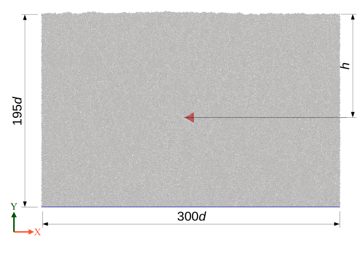
In this work, we employed the Discrete Element Method (DEM)[18] to study the forces on variously-shaped objects being dragged through a granular medium in the presence of gravity. The simulations were performed in two dimensions with periodic boundary conditions in the -direction. A gravitational field of magnitude acts along the negative direction and a wall, composed of particles of diameter , confines the simulation system along . We poured randomly 63000 particles, of diameters uniformly distributed in the range , from above after placing an intruder in the system. The particles were allowed to settle under the influence of gravitational and dissipative forces (discussed later) until the energy of the system reached a minimum. The simulation system spans along the direction while the free surface is present at a height of about measured from the bottom. The depth of the center of mass of the intruder from this free surface is denoted by . The density (mass per unit area) is set as . left bot right top

The intruder is displaced at a constant velocity along the positive -direction for a total distance of 1200. We considered 7 different shapes in our study: a square (S1), a rectangle (S2), a disk (S3), an ellipse with major axis aligned with the direction of motion of the intruder (S4), an ellipse with minor axis aligned with the x- direction (S5), an equilateral triangle with edge pointing opposite to the moving direction (S6) and an equilateral triangle with edge pointing along the moving direction (S7): See Fig. 1. The cross-section facing the flow of all shapes has the same length of . Fig. 2 shows an initial configuration for S6 at a depth of .
To update the positions and velocities of particles as a function of space and time, one needs to compute the forces they experience due to interaction with the neighboring particles. The normal and tangential contact forces between particles and were calculated with the following expressions [19, 20].
| (1) |
| (2) |
where and and are the mass and diameter of particle , the spring constant in the normal direction and the spring constant in the tangential direction . The normal and tangential damping coefficients, and , were taken as . The upper limit of is restricted to for considering the slipping between contacts. The coefficient of friction was varied between 0 to 0.5. is the unit vector along the line joining the centers of particles and and is the overlap between the two particles in the normal direction. stands for the accumulated tangential displacement vector. Relative velocities in the normal and tangential directions are represented as and , respectively. The model adopted is consistent with a velocity-dependent coefficient of restitution[21].
3 Results and Discussion
In this section, we present the results for all seven intruder shapes (see Fig. 1). The intruder moves at a constant velocity along the positive direction at depth . The study was carried out for various velocities , depth , and coefficient of friction . This section has been further split into five subsections. Subsection 3.1 presents the drag on the intruder for various velocities and coefficient of friction at a constant depth . Subsection 3.2 addresses the particle contacts on the intruder for various and at a constant depth and kinetic drag regimes. Subsection 3.3 provides the details on the lift force experienced by the intruder for various and at a constant depth . Subsection 3.4 explains the depth dependence of forces on the intruder for velocities and and . Lastly, Subsection 3.5 examines the distribution of forces around the intruder for various velocities at a fixed and . Quantities such as drag , lift , and number of contacts reported in this work have been calculated by averaging over several configurations after the intruder achieves a mean steady state behavior, i.e., the instantaneous drag fluctuates around a well defined mean.
3.1 Drag on the moving intruder
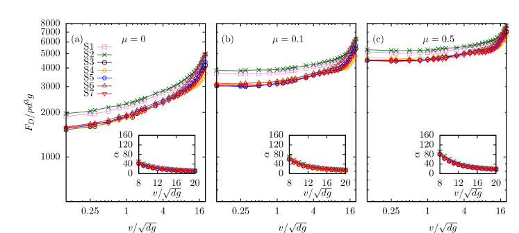
In this subsection, we present and discuss the drag on the moving intruder at several velocities and coefficients of friction . The drag against velocity (log-log plot) for and is shown in Fig. 3 (a), (b) and (c), respectively, for all the shapes. Additionally, is shown in the insets of each figure.
A minimum force, known as the yield drag [24, 25, 26], is required to initiate the motion of an object in granular media. There is also a kinetic term associated with the drag force on the intruder[26]. Therefore, we can write the drag as where is the yield drag necessary to initiate the motion, while is the kinetic drag. Assuming that the drag for the lowest velocity at which we performed our simulations in Fig. 3 gives us the yield drag, is highest for S2 followed by S1 for all . The other shapes have nearly identical yield drag (within seven percent of each other) for all values of considered.
It is known from a few published studies [25, 26, 27, 28, 24] that the drag regimes and drag laws in granular media are strongly correlated with the intruder’s velocity. In the present work, we observe that without friction, the drag increases gradually with (see Fig. 3(a)). However, in the presence of friction, specifically, and , we observe a constant drag regime at low velocities (see Fig. 3(a) and (b)). Hilton and Tordesillas[25] and Kumar et al[26] studied these drag regimes in the context of a dimensionless Froude number which is the ratio of two timescales associated with the falling of grains in the wake and the forward motion of the intruder (assuming the intruder dimensions are much larger than the grains). They suggested that the constant drag regime exists for . Applying their individual definitions of to our shape S3, Ref. [25] predicts that the constant drag regime should persist until , while Ref. [26] predicts the constant drag regime to exist until . Both definitions predict a constant drag regime in the velocity range very close to what we have observed in our study. While it is not clear how this definition of can be extended to non-spherical intruders, we observe that the constant drag regime occurs for almost the same velocity range for all the shapes.
Beyond the constant drag regime, the drag on the intruder increases with velocity. The slope of the curve on the log-log plot seems to be varying with suggesting that, for some constant , is not valid for a granular medium. The kinetic drag contribution to the drag dominates yield drag at high velocities. This can be observed in the insets of Fig. 3 where approaches a constant value. We shall elaborate further on and the drag regimes in the next subsection. By comparing directly the values of at higher velocities (), we note that the drag forces are in the order: , where is the drag for shape . Even though the differences are not large, this trend is observed consistently for all velocities higher than , and for all considered in our study. At velocities lower than 1.23 (), the trend is: .
Albert et al[9], in their study of the effect of shape of slowly moving object in a granular medium on jamming of grains around the object, highlighted that (a) streamlining the intruder significantly reduces the resistance offered by the granular medium to its motion, and (b) the increase in the drag on intruders that are longer in the flow direction is not due to the increase is due to the creation of a more jammed state in front of the intruder. Ding et al. [10] demonstrated that the local surface stress on an intruder is approximately equal to that on a plate oriented at the same angle as the local surface and moving at the same velocity and depth. Therefore, one could calculate the forces on an intruder by summing up the individual contributions of these stresses.
At low velocities (see Fig. 3), it is evident that streamlining an object significantly reduces the drag. An example of this would be the shape S2 (a rectangle) and S4 (an ellipse) of along and , respectively. Since an ellipse is more streamlined than a rectangle of similar dimensions, the latter has a higher drag than the former. The streamlining of a body reduces the drag since the force chains applying a force of at a point on the intruder contributes only to the drag, where is the tangential orientation of the intruder at point with axis ( corresponds to the direction of motion). If the force chains developed were equally strong, streamlining of a body would significantly reduce drag due to only a component of force being added.
Moreover, similar shapes such as S3, S4, and S5 have identical drag at low velocities suggesting that viscous contribution is not a major contribution to the drag force in granular media[9]. Although S4 is the longest and it creates the most jammed force chains in front of itself compared to S3 and S5, the force chains may tend to occur more laterally, thus, contributing less to the drag. However, it must be emphasized that if the bodies are equally streamlined, the drag increases with the length of the intruder at low velocities as can be seen from for shapes S1 and S2. This is because longer shapes (Fig. 3) delay the collapse of force chains in the intruder’s wake allowing those with higher stress to be formed in front of the intruder. Also since the forward facing surfaces of S1, S2 and S6 are blunt (), the force chains contribute more to drag compared to the other shapes. Moreover, the shape S6 allows the force chains to collapse almost immediately and thus, has lower drag than S1 or S2. S7 is also streamlined and, therefore, has less drag than S1 or S2 at lower velocities. This will be shown in later subsections.
As previously stated, at higher velocities, the drag forces are in the order . Firstly, S1, S2 and S6 are subject to an approximately equal drag, unlike at low velocities. Interestingly, Ding et al[10] showed that stress acting on a flat plate being dragged in granular media is identical to the small element on the intruder with a similar orientation to the flow , irrespective of the shape of the intruder. Since the front faces (side facing the flow) of these three intruders are oriented at the same angle to the flow, they experience the same magnitude of stress on the front face. Additionally, the other faces contribute very little to the drag as they do not experience contacts with the grains. This leads to the three shapes S1, S2 and S6 having an identical drag. It is noteworthy that, at low velocities, the drag is not equal for the three shapes, because of the way these shapes hinder the jamming and collapse of grains around them.
Other shapes with curved front surfaces experience a lower drag than S1, S2, and S6. The curved surfaces contribute times the normal force on the intruder’s surface to the drag. Therefore, the more blunt an object is, the more drag it experiences. Hence, S5 has a lower drag than S1, S2, and S6, but higher than S3. As the shape becomes less blunt, the drag is further reduced with S4 having a lower drag than S3. Interestingly, S7 also has a higher than S4 because two of the sides of S7 are tilted at an angle of to the flow. This is very close to the angle at which a plate moved through granular media experiences the maximum stress[10]. S3 and S7 experience similar drag due to the summation of drag components being almost similar. We discuss the force profiles on the intruders in Sec. 3.5.
3.2 Number of contacts, kinetic drag, and drag regimes
In order to understand the forces acting on an intruder, it is imperative to reflect on the role of the grains in contact with the intruder: it is these grains that are ‘directly’ responsible for the forces. The average number of grain contacts changes with the intruder’s shape as well as its velocity. Therefore, in this subsection, we present the results and discussion on and the relation between , and the drag regimes.
| Shape | ||
|---|---|---|
| S1 | 0.20 | 0.25 |
| S2 | 0.24 | 0.20 |
| S3 | 0.22 | 0.32 |
| S4 | 0.17 | 0.21 |
| S5 | 0.27 | 0.37 |
| S6 | 0.30 | 0.33 |
| S7 | 0.34 | 0.33 |
The number of contacts is calculated by averaging over several configurations after the intruder has reached a steady-state behavior, i.e., when the drag force fluctuates around a well-defined mean. Of course, is a strong function of the shape of the intruder, but it does not imply that two shapes with same number of contacts at a given experience equal forces. For example, a blunt or streamlined object may a have similar number of contacts.
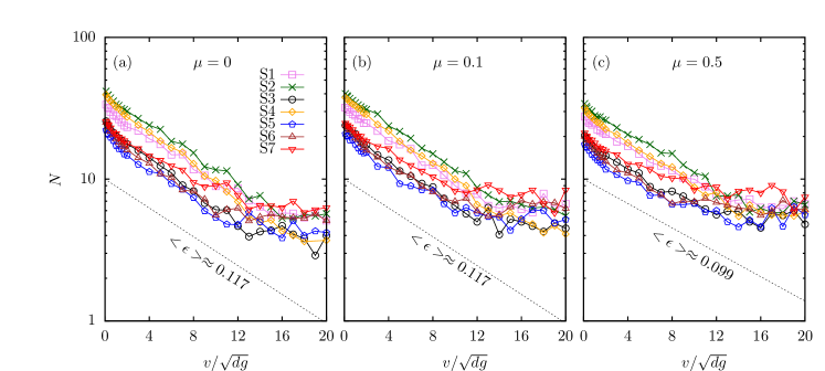
The variation of with is shown in Fig. 4 (a), (b), and (c) on a semi-log plot for 0.1, and 0.5, respectively. Two distinct regimes can be identified; an exponential one in which and a second in which is constant. The latter seems to be in the same velocity range in which the dependence of drag force is expected. We do not exactly understand the physical picture behind this saturation, but it is consistently present for all the shapes and for all the considered in our study. However, this saturation value can be approximated as , where is the packing fraction of the bed and is the cross-section length perpendicular to the direction of motion. Let where is the number of contacts in the yield limit, which is roughly equal to where is the perimeter of the obstacle. Therefore, . We have compared this rough theoretical estimate of with that obtained from the numerical simulations in Table 1. Additionally, we observe that as can be seen in Fig. 4 (a), (b) and (c) and the value of for each individual shape and is presented in Table 2.
| Shape | ||||||
|---|---|---|---|---|---|---|
| S1 | 0.0 | 0.133 | 1.064 | 0.981 | 1.970 | 0.983 |
| 0.1 | 0.120 | 1.319 | 0.993 | 2.168 | 0.973 | |
| 0.5 | 0.099 | 1.296 | 0.999 | 2.411 | 0.976 | |
| S2 | 0.0 | 0.115 | 1.106 | 0.984 | 2.244 | 0.974 |
| 0.1 | 0.119 | 1.403 | 0.997 | 2.591 | 0.991 | |
| 0.5 | 0.100 | 1.440 | 0.961 | 2.420 | 0.986 | |
| S3 | 0.0 | 0.126 | 1.130 | 0.986 | 1.752 | 0.922 |
| 0.1 | 0.123 | 1.290 | 0.997 | 1.938 | 0.942 | |
| 0.5 | 0.099 | 1.186 | 0.991 | 2.094 | 0.955 | |
| S4 | 0.0 | 0.132 | 1.126 | 0.993 | 2.143 | 0.988 |
| 0.1 | 0.133 | 1.301 | 0.997 | 2.300 | 0.978 | |
| 0.5 | 0.116 | 1.363 | 0.991 | 2.188 | 0.975 | |
| S5 | 0.0 | 0.122 | 1.063 | 0.983 | 1.422 | 0.905 |
| 0.1 | 0.113 | 1.25 | 0.994 | 1.746 | 0.945 | |
| 0.5 | 0.090 | 1.191 | 0.979 | 2.022 | 0.945 | |
| S6 | 0.0 | 0.122 | 1.106 | 0.981 | 1.296 | 0.966 |
| 0.1 | 0.113 | 1.327 | 0.998 | 1.601 | 0.951 | |
| 0.5 | 0.094 | 1.296 | 0.993 | 2.08 | 0.976 | |
| S7 | 0.0 | 0.092 | 1.001 | 0.994 | 1.579 | 0.951 |
| 0.1 | 0.099 | 1.292 | 0.997 | 1.807 | 0.911 | |
| 0.5 | 0.073 | 1.225 | 0.983 | 2.147 | 0.932 | |
| Mean | 0.0 | - | 1.001 | - | 1.579 | - |
| 0.1 | - | 1.292 | - | 1.807 | - | |
| 0.5 | - | 1.225 | - | 2.147 | - |
Based on plots of and versus for and by comparing their respective behaviors for all the intruder shapes considered in the present study, we propose a three-regime model for the average drag force acting on the intruder. In the first, which is observed in the range , the drag is constant; the second occurs in the range and the third for . In the remainder of this subsection, we explore the dependence of the kinetic drag on the velocity for each of these regimes.
Each contact exerts a force on the intruder whose magnitude depends on its location with respect to the intruder’s line of motion. It is difficult to correlate the average number of contacts with the force on the intruder. A previous study [25] proposed with , but they considered only the first two drag regimes. Here we assume that can vary depending on the regime:
| Regime I: | (3) | |||
| Regime II: | (4) | |||
| Regime II: | (5) |
Best-fit parameters of these equations to our simulation data, along with their coefficient of determination, are presented in Table 2. In regime II, it can be seen that for all shapes in accord with the previous results [25] for . As for the regime III, is consistent with a dependence of kinetic drag with velocity. Except for the frictionless () systems where the trends are not clear, the proposed regimes work well for all the shapes with and .
3.3 Lift on the moving intruder
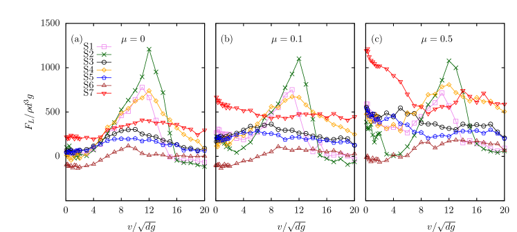
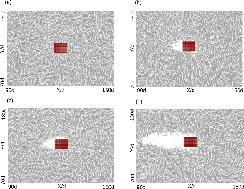
The component of the force on the intruder perpendicular to the flow direction is defined as the lift force, . Figure 5 shows the variation in as a function of the intruder’s velocity () for various coefficients of friction ( = 0, 0.1 and 0.5). For a clear exposition of the trends, we consider three velocity regimes: (i) low velocities (); (ii) intermediate velocities (); and (iii) high velocities (). For (Fig. 5(a)), a maximum in for all intruder shapes is observed in the intermediate velocity regime and is ordered as follows: . For most of the shapes saturates in the third regime. The highest is observed for (rectangle) in the intermediate regime. In both frictional and frictionless systems the maximum lift force for this shape is observed at followed by a sharp decrease. The non-monotonic behavior of the lift force is result of flow detachment from the intruder. One such example is shown in Fig. 6 depicting simulation snapshots of the flow region around the shape for at different velocities. For the granular particles just slide past the intruder without leaving a trail behind it. At flow detachment from the upper surface of the intruder is evident. This can be attributed to the presence of a free surface at the top and a confined wall at the bottom of the assembly of particles. As a result, the particles below the intruder exert a net upward force. As increases, flow detachment continues to occur only from above the intruder but not below it. The expansion of flow detachment above the intruder is observed until . Beyond , however, the intruder imparts more energy to the granular particles in its path, which eventually results in flow detachment from both the upper and lower surfaces of the intruder as shown in Fig. 6 (d) for .
It is generally observed that above a certain velocity particle contact only occurs on the leading side of the intruder with flow detachment from both its top and bottom surfaces. This flow detachment plays an important role in the decrease of beyond a certain for shapes (square), (rectangle) and (ellipse with the major axis aligned with the -direction), compared to the other intruders. The lift force on the equilateral triangle (with edge pointing to the moving direction), disc , and ellipse major shapes varies little with for . This could be due to the maximum particle interaction being concentrated on the frontal part. Interestingly, a negative is observed for an equilateral triangle with its edge pointing opposite to its direction of motion () in the low velocity regime. In this case, particles traversing the edges of the blunt surface exert more force on the upper inclined surface than that on the lower one. This is because the particles fall on the upper inclined surface of , while the particles have to move against gravity to reach the lower inclined surface. It is also evident that the lift force saturates for most of the shapes in higher velocity regime.
For systems with friction coefficients and , the lift force on and is higher than on the other shapes in the intermediate velocity regime. The reason being the flow detachment and the larger contact surface around the top and bottom region of the intruder. The lift force on shapes and show little variation for for a range of , while for the lift force is higher for and in the low velocity regime and then gradually saturates in the high velocity regime. Unlike the other shapes the net lift force on is small for all values of and is negative in the low velocity regime.
The two equilateral triangles and have different orientations (edges pointing opposite and along the moving direction, respectively). This significantly impacts the experienced by the two shapes as seen in Fig. 5. Ding et al. have also stated that is sensitive to the cross-section of the intruder. The has higher than the for all the friction coefficients. The particles in front of the intruder collide with a flat surface in the case of , whereas they collide with a ”V” shaped surface with its edge pointing in the direction of the intruder’s motion for the case of . For the lift force was maximum at low velocity regime for the with gradually saturating at higher velocity(Fig. 5(b)). The shape has an pointed edge at the moving direction of intruder with its two frontal surfaces inclined to each other at angle and a blunt back. It does have a larger area for particle contact at the leading surface. At low velocities the particles coming in contact at the upper inclined surface slides past the intruder. While there is an accumulation of particles at the bottom front surface due to the confined wall at the bottom. Thus giving it a push in the positive y-direction. This can be a reason that is having higher at low velocity regime.
Another interesting observation is the independence of on the intruder’s velocity in the range for for all the shapes. This behavior is in contrast with the trend of drag force, where a gradual increase is observed with intruder velocity. For both frictional and frictionless systems, the maximum is observed for (rectangle) in the intermediate velocity regime. The lift force has a dependence on the orientation of the intruder, for example, and exhibited completely different behavior to each other.
3.4 Depth-dependence of forces on the moving intruder
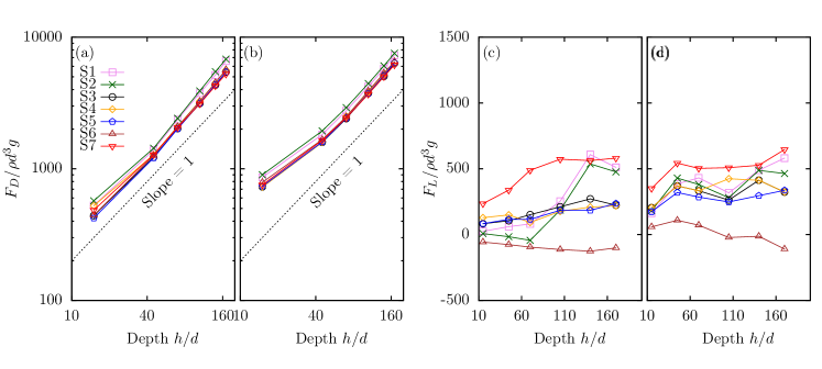
Albert et al[9] observed a nonlinear depth dependence of the drag force on a discrete object moving at a very low velocity immersed in a granular bed at a depth of 40 - 150 (equivalent to 44 - 166 granular bed particles depth). Guillard et al.[29] observed a depth-independent drag force on a cylindrical object immersed deep (120 particle lengths or more) in a granular medium and rotated about the vertical axis. A few studies [11, 30, 31] also reported a linear depth dependence. In the context of these results, we compare on the different intruder shapes as a function of their immersion depth in Fig. 7 (a) and (b). The results are shown for two intruder velocities = 1 and 5 at . In the simulations, the intruder is placed at six different depths . increases linearly with an increase in for all the intruders considered here, confirming that the drag is proportional to the hydrostatic pressure. In granular medium the number of particles above the intruder increases with an increase in its depth thus increasing hydrostatic pressure. The for the various h/d at =1 and can be ordered as: . The same trend is also observed for . The and experiences the maximum drag for all for the two shown in the plots while the other shapes have identical within five percent of each other at a particular depth. Moreover, the difference between the highest () and lowest () drag forces calculated for one random depth is not more than .
It has been reported in the literature that the lift force either saturates [14, 15] or increases [10] with the immersion depth of intruder in a granular medium. To determine the shape and depth dependence, we plot the lift force as a function of for two intruder velocities, =1 and 5, at in Fig. 7 (c) and (d). Minimal change in lift force for intruders , and is observed at . The lift force on intruders and increases sharply below a certain depth for . For the same velocity on increases up to a certain depth and then saturates with further increase in the depth. For there is a fluctuation in lift force for all the intruders except for which shows a gradual decrease in with an increase in . and with the same geometry but different orientation in the -direction have the lowest and highest lift forces, respectively for almost at all the depths considered. The lift force acting on moving at =1 shows little variation with depth, while at it decreases with the intruder depth.
While the results of Fig. 7 suggest that the relation between drag and depth can be easily understood the same is not true for the lift force, even though both forces result from the repulsive interactions between granular particles and the intruder. The lift force experienced by the intruder also depends upon the number of particle contacts at its upper and lower surface. So the forces depend on the specific region of contact around the intruder surface. Thus if the sum of forces acting perpendicularly on the lower surface of the intruder is more due to the particle contacts, then it experiences a positive and otherwise it has a negative . In the next section, we examine the force distribution on the intruder surface and how it influences the drag and lift forces.
3.5 Force profile along the surface of the intruder
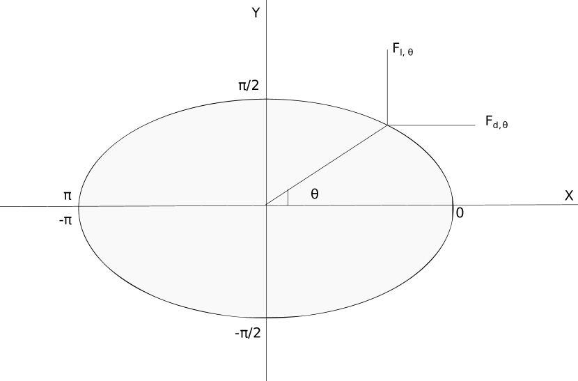
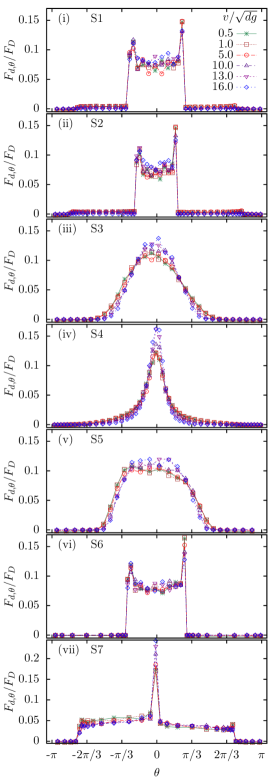
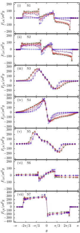
To develop a better understanding of how the forces act around the periphery of a moving intruder, the force distribution as a function of the angle of contact (),(definition of in Fig. 8) is analyzed. Positions on the upper (lower) surfaces correspond to positive (negative) angles. The number of particles in contact is more at the front of the intruder with an increase in while on the backside there is a decrease as shown in Fig. 9. The shapes , and , having a blunt face to the moving direction has higher drag for value, to . This is due to the maximum particle contact being concentrated at the face of the intruder in the moving direction. It is also observed that there is a sharp increase in drag at the leading edges. This is because when the blunt-faced intruders are moving within the medium, they push the particles along with it. These colliding particles will have an opposite perpendicular force acting on the blunt face of the intruder whereas at the leading edges the force with which the particles interact will be more due to the gravitational force that comes into play. There are more particle contacts at the backside of the intruder at low velocities compared with the case of high velocities(no visible contacts as shown in Fig. 6). The empty wake created at high behind the intruder is due to the detachment of particles around the obstacles at high drag speeds [11]. The drag force experienced by the intruder is mainly due to its contacts with particles at the front in the direction of motion of the intruder. At the back of the intruder surface, the particles exert minimal contact forces as they just slide down due to gravity after contacting the leading surface of the intruder. Thus the force is almost zero for . The curved intruders and have a maximum drag force for . The shapes and which have a pointed edge to its direction of motion, experiences a higher drag at . The shape has maximum drag force at its pointed edges and then followed by a sharp decrease at the sides of the intruder tilted at an angle of to the moving direction.
Fig. 9 (b) shows the distribution of lift force around the intruder surface for various . The shapes , and exhibit similar lift force profiles for as they present a blunt face in the leading direction. (rectangle) experiences high lift force for . The curved intruders and exhibit a higher positive lift force suggesting a larger number of particle contacts on their lower surface. This is due to their more streamlined form compared to other shapes. The equilateral triangles and show different lift force profiles. The former, with its blunt front face, experiences essentially zero lift on its trailing sides (), while the experiences strong positive lift forces on its lower leading face and a weaker negative lift force on its upper leading face, .
4 Conclusions
We have presented numerical simulation results of an intruder dragged horizontally through a granular medium to understand the drag and lift forces it experiences as a function of its velocity (), immersion depth () and shape. The drag force gradually increases with in frictionless systems (), while when friction is present we observe a constant drag regime at low velocities. For a fixed cross section, the drag force depends weakly on the intruder shape. In contrast, the lift force has a strong shape dependence. It may increase in a certain velocity range but at higher velocities a decline in the lift force is noticed. The intruder shape has a major effect on the distribution of contacts around its surface, which explains the strong lift experienced by certain shapes. The force profiles around the intruder surface resulting from granular contacts exhibit a strong angular dependence.
Conflicts of interest
There are no conflicts to declare.
Acknowledgements
We thank Param-Ishan, computing facility at IIT Guwahati.
References
References
-
[1]
H. M. Jaeger, S. R. Nagel, R. P. Behringer,
Granular solids,
liquids, and gases, Rev. Mod. Phys. 68 (1996) 1259–1273.
doi:10.1103/RevModPhys.68.1259.
URL https://link.aps.org/doi/10.1103/RevModPhys.68.1259 -
[2]
F. Fan, E. J. R. Parteli, T. Pöschel,
Origin of
granular capillarity revealed by particle-based simulations, Phys. Rev.
Lett. 118 (2017) 218001.
doi:10.1103/PhysRevLett.118.218001.
URL https://link.aps.org/doi/10.1103/PhysRevLett.118.218001 -
[3]
S. Kumar, M. Dhiman, K. A. Reddy,
Magnus effect in
granular media, Phys. Rev. E 99 (2019) 012902.
doi:10.1103/PhysRevE.99.012902.
URL https://link.aps.org/doi/10.1103/PhysRevE.99.012902 - [4] D. J. Goldfarb, B. J. Glasser, T. Shinbrot, Shear instabilities in granular flows, Nature 415 (6869) (2002) 302.
-
[5]
J. L. Vinningland, O. Johnsen, E. G. Flekkøy, R. Toussaint, K. J.
Måløy,
Granular
rayleigh-taylor instability: Experiments and simulations, Phys. Rev. Lett.
99 (2007) 048001.
doi:10.1103/PhysRevLett.99.048001.
URL https://link.aps.org/doi/10.1103/PhysRevLett.99.048001 - [6] A. Huminic, G. Huminic, Aerodynamic study of a generic car model with wheels and underbody diffuser, International Journal of Automotive Technology 18 (3) (2017) 397–404.
- [7] D. Bushnell, Aircraft drag reduction—a review, Proceedings of the Institution of Mechanical Engineers, Part G: Journal of Aerospace Engineering 217 (1) (2003) 1–18.
-
[8]
R. Albert, M. A. Pfeifer, A.-L. Barabási, P. Schiffer,
Slow drag in a
granular medium, Phys. Rev. Lett. 82 (1999) 205–208.
doi:10.1103/PhysRevLett.82.205.
URL https://link.aps.org/doi/10.1103/PhysRevLett.82.205 -
[9]
I. Albert, J. G. Sample, A. J. Morss, S. Rajagopalan, A.-L. Barabási,
P. Schiffer,
Granular drag on a
discrete object: Shape effects on jamming, Phys. Rev. E 64 (2001) 061303.
doi:10.1103/PhysRevE.64.061303.
URL https://link.aps.org/doi/10.1103/PhysRevE.64.061303 -
[10]
Y. Ding, N. Gravish, D. I. Goldman,
Drag induced
lift in granular media, Phys. Rev. Lett. 106 (2011) 028001.
doi:10.1103/PhysRevLett.106.028001.
URL https://link.aps.org/doi/10.1103/PhysRevLett.106.028001 - [11] F. Q. Potiguar, Y. Ding, Lift and drag in intruders moving through hydrostatic granular media at high speeds, Physical Review E 88 (1) (2013) 012204.
- [12] H. Katsuragi, K. Anki Reddy, K. Endo, Shape dependence of resistance force exerted on an obstacle placed in a gravity-driven granular silo flow, AIChE Journal 64 (11) (2018) 3849–3856.
- [13] F. Q. Potiguar, Lift force on an asymmetrical obstacle immersed in a dilute granular flow, Physical Review E 84 (6) (2011) 061302.
-
[14]
F. Guillard, Y. Forterre, O. Pouliquen,
Lift forces in granular media,
Physics of Fluids 26 (4) (2014) 043301.
arXiv:https://doi.org/10.1063/1.4869859, doi:10.1063/1.4869859.
URL https://doi.org/10.1063/1.4869859 - [15] B. Debnath, K. K. Rao, P. R. Nott, The lift on a disc immersed in a rotating granular bed, AIChE Journal 63 (12) (2017) 5482–5489.
-
[16]
R. D. Maladen, Y. Ding, C. Li, D. I. Goldman,
Undulatory swimming
in sand: Subsurface locomotion of the sandfish lizard, Science 325 (5938)
(2009) 314–318.
doi:10.1126/science.1172490.
URL http://science.sciencemag.org/content/325/5938/314 -
[17]
Y. Ding, S. S. Sharpe, A. Masse, D. I. Goldman,
Mechanics of undulatory
swimming in a frictional fluid, PLOS Computational Biology 8 (12) (2012)
1–13.
doi:10.1371/journal.pcbi.1002810.
URL https://doi.org/10.1371/journal.pcbi.1002810 -
[18]
P. A. Cundall, O. D. L. Strack,
A discrete numerical model
for granular assemblies, Géotechnique 29 (1) (1979) 47–65.
arXiv:https://doi.org/10.1680/geot.1979.29.1.47, doi:10.1680/geot.1979.29.1.47.
URL https://doi.org/10.1680/geot.1979.29.1.47 - [19] N. V. Brilliantov, F. Spahn, J.-M. Hertzsch, T. Pöschel, Model for collisions in granular gases, Phys. Rev. E 53 (5) (1996) 5382.
- [20] G. S. G. T. C. H. D. L. L. E. Silbert, D. Ertas, S. J. Plimpton, Granular flow down an inclined plane: Bagnold scaling and rheology, Phys. Rev. E 64 (2001) 051302.
- [21] T. Schwager, T. Poschel, Coefficient of normal resitution of viscous particles and cooling rate of granular gases, Phys. Rev. E. 57 (1998) 650.
- [22] S. Plimpton, P. Crozier, A. Thompson, Lammps-large-scale atomic/molecular massively parallel simulator, Sandia National Laboratories 18.
- [23] W. Humphrey, A. Dalke, K. Schulten, VMD – Visual Molecular Dynamics, Journal of Molecular Graphics 14 (1996) 33–38.
-
[24]
Y. Takehara, K. Okumura,
High-velocity
drag friction in granular media near the jamming point, Phys. Rev. Lett. 112
(2014) 148001.
doi:10.1103/PhysRevLett.112.148001.
URL https://link.aps.org/doi/10.1103/PhysRevLett.112.148001 -
[25]
J. E. Hilton, A. Tordesillas,
Drag force on a
spherical intruder in a granular bed at low froude number, Phys. Rev. E 88
(2013) 062203.
doi:10.1103/PhysRevE.88.062203.
URL https://link.aps.org/doi/10.1103/PhysRevE.88.062203 - [26] S. Kumar, K. Anki Reddy, S. Takada, H. Hayakawa, Scaling law of the drag force in dense granular media, arXiv e-prints (2017) arXiv:1712.09057arXiv:1712.09057.
-
[27]
D. Wang, Y. Yang, W. Du,
The
drag on a vibrated intruder moving in the confined granular media, Powder
Technology 286 (2015) 385 – 391.
doi:https://doi.org/10.1016/j.powtec.2015.08.027.
URL http://www.sciencedirect.com/science/article/pii/S0032591015300279 - [28] S. Takada, H. Hayakawa, Drag law of two-dimensional granular fluids, Journal of Engineering Mechanics 143 (1) (2016) C4016004.
- [29] F. Guillard, Y. Forterre, O. Pouliquen, Depth-independent drag force induced by stirring in granular media, Phys. Rev. Lett. 110 (2013) 138303.
-
[30]
F. m. c. Guillard, Y. Forterre, O. Pouliquen,
Origin of a
depth-independent drag force induced by stirring in granular media, Phys.
Rev. E 91 (2015) 022201.
doi:10.1103/PhysRevE.91.022201.
URL https://link.aps.org/doi/10.1103/PhysRevE.91.022201 - [31] A. Panaitescu, X. Clotet, A. Kudrolli, Drag law for an intruder in granular sediments, Physical Review E 95 (3) (2017) 032901.