Drive Dependence of the Hall Angle for a Sliding Wigner Crystal in a Magnetic Field
Abstract
We numerically examine the depinning and sliding dynamics of a Wigner crystal in the presence of quenched disorder and a magnetic field. In the disorder-free limit, the Wigner crystal Hall angle is independent of crystal velocity, but when disorder is present, we find that Hall angle starts near zero at the depinning threshold and increases linearly with increasing drive before reaching a saturation close to the disorder free value at the highest drives. The drive dependence is the result of a side jump effect produced when the charges move over pinning sites. The magnitude of the side jump is reduced at the higher velocities. The drive dependent Hall angle is robust for a wide range of disorder parameters and should be a generic feature of classical charges driven in the presence of quenched disorder and a magnetic field.
There are a wide range of systems containing quenched disorder that exhibit depinning and sliding phenomena Fisher (1998); Reichhardt and Reichhardt (2017), including vortices in type-II superconductors Bhattacharya and Higgins (1993); Blatter et al. (1994), driven charge density waves Grüner (1988); Danneau et al. (2002), skyrmions Schulz et al. (2012); Reichhardt et al. (2015a); Legrand et al. (2017); Jiang et al. (2017), and colloids on substrates Reichhardt and Olson (2002); Pertsinidis and Ling (2008); Bohlein et al. (2012). Such systems can exhibit a threshold for motion and nonlinear velocity-force curves as a function of increasing external drive. In many cases, the depinning and sliding dynamics can be imaged directly and compared to bulk transport measures, showing that different types of sliding phases are possible including moving crystals and smectic states Reichhardt and Reichhardt (2017).
A Wigner or electron crystal is also expected to exhibit depinning and sliding under an external drive Andrei et al. (1988); Goldman et al. (1990); Williams et al. (1991); Jiang et al. (1991); Zhu et al. (1994); Cha and Fertig (1994); Chitra et al. (1998); Perruchot et al. (1998); Abrahams et al. (2001); Reichhardt et al. (2001); Reichhardt and Olson Reichhardt (2004); Zhang et al. (2014); Jang et al. (2017); Knighton et al. (2018); Brussarski et al. (2018). Experimentally, the presence of nonlinear current-voltage curves or the onset of conduction noise have been argued as providing evidence for the depinning and motion of Wigner crystals Goldman et al. (1990); Williams et al. (1991); Jiang et al. (1991); Zhu et al. (1994); Cha and Fertig (1994); Perruchot et al. (1998); Abrahams et al. (2001); Reichhardt et al. (2001); Reichhardt and Olson Reichhardt (2004); Brussarski et al. (2018); however, unlike superconducting vortices or colloidal particles, direct visualization of the depinning process is not possible, so additional transport measures for detecting the sliding of a Wigner crystal would be very valuable. If the sliding Wigner crystal is subjected to a magnetic field, it moves at a Hall angle which is proportional to the strength of the field, but relatively little is known about how the presence of a finite Hall angle could affect depinning or the sliding motion of a Wigner crystal. Based on theoretical calculations in the perturbative limit for a Wigner crystal in a magnetic field interacting with weak quenched disorder, it has been argued that the disorder will not affect the Hall angle Zhu et al. (1994); however, it is not clear what happens in the case of strong disorder.
Depinning and sliding phenomena also appear in magnetic skyrmion systems Schulz et al. (2012); Reichhardt et al. (2015a); Legrand et al. (2017); Jiang et al. (2017), and it has been shown that the skyrmion dynamics are very similar to those of electrons in a magnetic field Schulz et al. (2012); Nagaosa and Tokura (2013). In particular, the skyrmion motion exhibits a Hall angle with a value that depends on the materials parameters Nagaosa and Tokura (2013). Simulations of skyrmion motion in the presence of disorder reveal that the skyrmions have a finite depinning threshold and that the skyrmion Hall angle is not constant but has a drive dependence, in which the Hall angle starts near zero at depinning and increases with increasing drive until reaching the disorder free limit at high drives Reichhardt et al. (2015a); Legrand et al. (2017); Nagaosa and Tokura (2013); Kim and Yoo (2017); Díaz et al. (2017). This effect has now been observed directly in numerous imaging experiments Jiang et al. (2017); Litzius et al. (2017); Woo et al. (2018); Juge et al. (2019); Zeissler et al. (2020); Litzius et al. (2020). Since skyrmions are extended bubble-like objects, the current or disorder can distort the shape or change the size of the skyrmions, potentially generating the drive dependence of the skyrmion Hall angle Litzius et al. (2017); Juge et al. (2019); Litzius et al. (2020). Similar internal distortions could occur in a Wigner crystal. Size distortions do not appear to be required, however, since several simulations using point-like approximations for the skyrmions still found a strong drive dependence of the Hall angle Reichhardt et al. (2015a); Díaz et al. (2017); Gong et al. (2020), suggesting that this effect could be generic to other particle-like systems exhibiting a Hall angle in the presence of quenched disorder. In the particle-based skyrmion model, the drive dependence is the result of a velocity-dependent side jump effect, where a particle that passes through a pinning site undergoes a jump in the direction opposite to that of the Hall angle. The jumps are more pronounced at lower velocity Reichhardt et al. (2015a); Müller and Rosch (2015); Reichhardt et al. (2015b). The presence of such jumps for skyrmions suggests that a similar phenomenon could arise for any particle-like system with a Hall effect, such as a Wigner crystal in a magnetic field, and that the side jumps could be detected by measuring changes in the Hall angle as a function of drive. This would provide a new experimentally realizable method for confirming the presence of a sliding Wigner crystal.
We numerically examine a classical model for a Wigner crystal interacting with random disorder using molecular dynamics simulations. Previous studies of this model in the absence of a magnetic field showed that the system exhibits a depinning threshold and nonlinear current-voltage (I-V) curves Cha and Fertig (1994); Reichhardt et al. (2001); Reichhardt and Olson Reichhardt (2004). When a magnetic field is applied, a driven Wigner crystal in a pin-free system moves at a constant Hall angle. If pinning is present, there is a finite depinning threshold and the I-V curves become nonlinear. In addition, the Hall angle develops a strong drive dependence, starting at a value near zero just above depinning and saturating for high drives at a value close to that found in the pin-free or perturbative limit. The drive dependence arises when a charge undergoes a side jump effect upon interacting with the disorder sites. This effect can be confirmed by measurements of the conduction both parallel and perpendicular to the drive. It is predicted to be robust for a wide range of disorder strength and intrinsic Hall angles, and it occurs for both a Wigner crystal and a Wigner glass. The drive-dependent Hall effect provides a new method to test for the presence of a Wigner crystal in solid state systems. Our results should also be general to other particle-like charged systems in quenched disorder and could be applied to charged colloids or dusty plasma systems under a magnetic field.
Simulation and System— We consider the dynamics of a two-dimensional assembly of classical electrons coupled to random pinning using molecular dynamics simulations. In the presence of a magnetic field, the overdamped equation of motion for electron is given by
| (1) |
Here is the repulsive electron-electron interaction potential, is the electron charge, is the force from the magnetic field which is oriented perpendicular to the electron velocity , is the pinning force, is the force from the externally applied drive, and is the damping term for the velocity component that is aligned with the net external force direction. The system contains electrons and pinning sites. The electron density is given by and the pin density is , where is the sample size. The pinning is modeled as harmonic traps with a maximum force of and radius . Here we consider the range to with . There are periodic boundary conditions in the and directions, and due to the long range nature of the electron-electron interactions, we use a Lekner summation technique as in previous studies Reichhardt et al. (2001); Reichhardt and Olson Reichhardt (2004).
Previous work with this model was performed in the limit of no magnetic field, , where it was found that when pinning is present, there is a finite depinning threshold for motion, above which the electrons move in the same direction as the external driving force Reichhardt et al. (2001); Reichhardt and Olson Reichhardt (2004). At finite , the combination of the damping and driving causes the electrons to move at a finite Hall angle with respect to the driving direction. Since , the Hall angle increases with increasing . For convenience, we measure the magnetic field in units of . We apply a dc driving force and measure the net velocity both parallel and perpendicular to the drive direction, and , giving a measured Hall angle of .
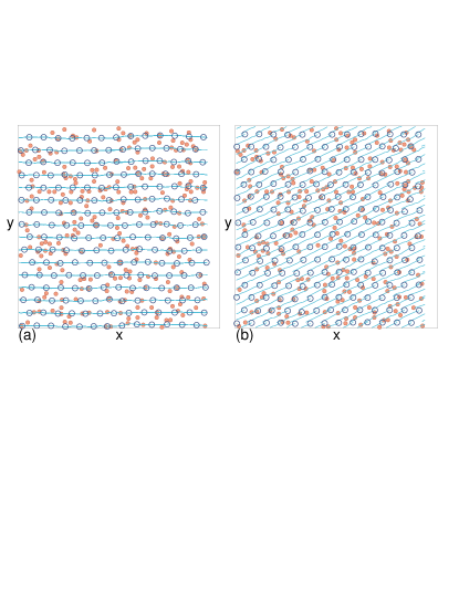
Results- In Fig. 1(a) we show the electrons, pinning sites, and electron trajectories for a system with , , electron density , and at where the drive is applied in the -direction. A Wigner crystal forms and moves parallel to the driving direction, giving . Figure 1(b) shows the same system at a finite magnetic field where the intrinsic or disorder free Hall angle is . Here the Wigner crystal moves at a finite angle of which is slightly less than the disorder free .
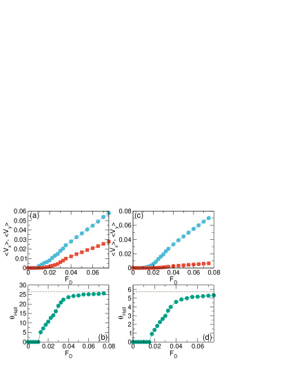
In Fig. 2(a) we plot and versus for the system in Fig. 1(b), and in Fig. 2(b) we show the corresponding versus . A depinning transition appears near , and the nonlinear behavior of the velocity-force curve becomes a linear behavior when . The dashed line in Fig. 2(b) indicates the pin-free value of , making it clear that when quenched disorder is present, there is an extended region of drive over which increases from zero and then at higher drives begins to saturate to a value close to the pin-free value. In Fig. 2(c,d) we plot , , and versus for a sample with a smaller magnetic field giving , where we observe the same behavior. We find that for a wide range of , , and , the general trends illustrated in Fig. 2 persist. Namely, there is a strong drive dependence of the Hall angle for drives up to 5 times the depinning threshold, followed by a crossover to a saturation regime with a weaker drive dependence.
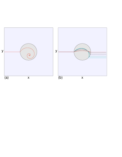
The velocity dependence of the Hall angle is the result of a side jump effect that occurs as the charges move though the pinning sites. To illustrate this effect, in Fig. 3 we plot the trajectories of a single electron interacting with a pinning site with . To better highlight the side jumps we use a large intrinsic Hall angle of , and we apply the external drive at an angle of from the axis so that in the absence of pinning the electron motion would be parallel to the axis. For the electron is trapped by the pinning site and undergoes a spiraling motion to reach the minimum energy position of the tilted pin, as shown in Fig. 3(a). For drives that are large enough to permit the electron to escape the trap, the electron trajectory is bowed across the pinning site and the point of exit of the electron is shifted in the negative direction compared to the point of entry. Figure 3(b) illustrates this effect for , 0.3, 0.4, 0.5, 0.7, 1.0, and 1.5, where the shift or jump gradually decreases in size with increasing . The side jumps are in the direction opposite to the Hall angle, so that for repeated interactions with pinning sites, the overall average electron motion is at an angle that is smaller than the intrinsic Hall angle . As the velocity of the electron increases, its direction of motion approaches .
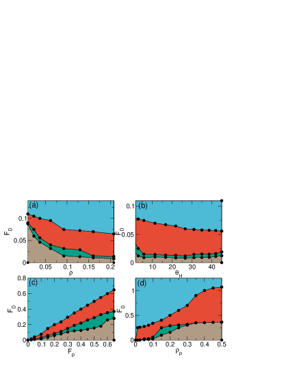
In Fig. 4(a) we plot a dynamic phase diagram as a function of versus electron density for the system in Fig. 2(c,d) at fixed pinning density for . We highlight the pinned state, the flowing state in which the Wigner crystal moves nearly along the intrinsic Hall angle direction, the regime in which the Hall angle increases linearly with drive, and the region where the crystal is moving but the Hall angle is zero. The latter regime is likely the result of a transverse barrier to motion. Such a transverse pinning effect can also arise in the absence of a magnetic field, as was proposed by Giamarchi and Le Doussal Giamarchi and Doussal (1996); Le Doussal and Giamarchi (1998) for vortices and other particle like objects moving over random disorder where the system forms one-dimensional moving channels. Previous numerical studies on sliding Wigner crystals in the absence of a magnetic field also found a transverse barrier for motion when an additional driving force was applied transverse to the sliding direction Reichhardt et al. (2001). In the present case, there is no additional applied transverse drive, but there is a finite Hall angle. In Fig. 4(a), for , the system forms a pinned Wigner glass rather than a pinned Wigner crystal, resulting in an increase in the depinning threshold with decreasing . Figure 4(b) shows a dynamic phase diagram as a function of versus the intrinsic Hall angle over the range to for the same system at fixed . In Fig. 4(c) we display the dynamic phase diagram as a function of versus pinning strength for a system with and , while in Fig. 4(d) we plot a dynamic phase diagram as a function of versus pinning density for a system with fixed , , and . These results indicate that the dynamic phases we observe are robust over a wide range of parameters.
Experimentally, the drive dependence of the Hall angle could be detected by measuring the transport above a depinning threshold in a system where a Wigner crystal is expected to form in the presence of a magnetic field. The drive dependence should be the most pronounced for large magnetic fields. There have already been some limited experimental studies of Wigner crystal sliding in a magnetic field which show that there is a minimum threshold longitudinal velocity which must be exceeded before sliding begins to occur in the transverse direction Perruchot et al. (2000). Other systems in which a similar effect could appear include a sliding quantum crystal Chen et al. (2006); Shashkin and Kravchenko (2019), creep motion of a Wigner crystal near melting Knighton et al. (2018); Ma et al. (2020) or driven electron liquid crystal states Cooper et al. (1999); Reichhardt et al. (2003); Wang et al. (2015). In some regimes in these systems, the particle picture breaks down, and in these regimes, the drive dependence of the Hall effect could be absent. Additionally, a similar drive dependent Hall effect should occur for charged colloids or dusty plasmas driven in the presence of quenched disorder and a magnetic field.
Summary— We have examined the depinning and sliding of a Wigner crystal in the presence of a magnetic field where in the absence of disorder the crystal moves at a Hall angle that is independent of the crystal velocity. When disorder is present, we find a pinned phase at low drive as well as a sliding phase in which the Hall angle is not constant but is initially zero near the depinning threshold and gradually increases with increasing drive until at high drives it reaches a saturation value close to the intrinsic Hall angle. This effect is the result of the side jump that occurs when the electrons move over the pinning sites, where the jump is in the direction opposite to the Hall angle. The magnitude of the side jump decreases with increasing velocity, which is similar to the behavior of the side jump effect observed for skyrmions driven over quenched disorder. We also find a regime in which the electrons slide only along the direction of drive and exhibit a finite barrier to transverse motion. The drive dependence of the Hall angle is robust over a wide range of intrinsic Hall angles, disorder densities, and pinning strengths, and could serve as a new way to confirm the existence of a sliding Wigner crystal. Our results should be general to the broad class of driven systems with a Hall angle in the presence of disorder.
Acknowledgements.
We gratefully acknowledge the support of the U.S. Department of Energy through the LANL/LDRD program for this work. This work was supported by the US Department of Energy through the Los Alamos National Laboratory. Los Alamos National Laboratory is operated by Triad National Security, LLC, for the National Nuclear Security Administration of the U. S. Department of Energy (Contract No. 892333218NCA000001).References
- Fisher (1998) D. S. Fisher, “Collective transport in random media: from superconductors to earthquakes,” Phys. Rep. 301, 113–150 (1998).
- Reichhardt and Reichhardt (2017) C. Reichhardt and C. J. Olson Reichhardt, “Depinning and nonequilibrium dynamic phases of particle assemblies driven over random and ordered substrates: a review,” Rep. Prog. Phys. 80, 026501 (2017).
- Bhattacharya and Higgins (1993) S. Bhattacharya and M. J. Higgins, “Dynamics of a disordered flux line lattice,” Phys. Rev. Lett. 70, 2617–2620 (1993).
- Blatter et al. (1994) G. Blatter, M. V. Feigel’man, V. B. Geshkenbein, A. I. Larkin, and V. M. Vinokur, “Vortices in high-temperature superconductors,” Rev. Mod. Phys. 66, 1125–1388 (1994).
- Grüner (1988) G. Grüner, “The dynamics of charge-density waves,” Rev. Mod. Phys. 60, 1129–1181 (1988).
- Danneau et al. (2002) R. Danneau, A. Ayari, D. Rideau, H. Requardt, J. E. Lorenzo, L. Ortega, P. Monceau, R. Currat, and G. Grübel, “Motional ordering of a charge-density wave in the sliding state,” Phys. Rev. Lett. 89, 106404 (2002).
- Schulz et al. (2012) T. Schulz, R. Ritz, A. Bauer, M. Halder, M. Wagner, C. Franz, C. Pfleiderer, K. Everschor, M. Garst, and A. Rosch, “Emergent electrodynamics of skyrmions in a chiral magnet,” Nature Phys. 8, 301–304 (2012).
- Reichhardt et al. (2015a) C. Reichhardt, D. Ray, and C. J. Olson Reichhardt, “Collective transport properties of driven skyrmions with random disorder,” Phys. Rev. Lett. 114, 217202 (2015a).
- Legrand et al. (2017) W. Legrand, D. Maccariello, N. Reyren, K. Garcia, C. Moutafis, C. Moreau-Luchaire, S. Coffin, K. Bouzehouane, V. Cros, and A. Fert, “Room-temperature current-induced generation and motion of sub-100 nm skyrmions,” Nano Lett. 17, 2703–2712 (2017).
- Jiang et al. (2017) W. Jiang, X. Zhang, G. Yu, W. Zhang, X. Wang, M. B. Jungfleisch, J. E. Pearson, X. Cheng, O. Heinonen, K. L. Wang, Y. Zhou, A. Hoffmann, and S. G. E. te Velthuis, “Direct observation of the skyrmion Hall effect,” Nature Phys. 13, 162–169 (2017).
- Reichhardt and Olson (2002) C. Reichhardt and C. J. Olson, “Colloidal dynamics on disordered substrates,” Phys. Rev. Lett. 89, 078301 (2002).
- Pertsinidis and Ling (2008) A. Pertsinidis and X. S. Ling, “Statics and dynamics of 2D colloidal crystals in a random pinning potential,” Phys. Rev. Lett. 100, 028303 (2008).
- Bohlein et al. (2012) T. Bohlein, J. Mikhael, and C. Bechinger, “Observation of kinks and antikinks in colloidal monolayers driven across ordered surfaces,” Nature Mater. 11, 126–130 (2012).
- Andrei et al. (1988) E. Y. Andrei, G. Deville, D. C. Glattli, F. I. B. Williams, E. Paris, and B. Etienne, “Observation of a magnetically induced Wigner solid,” Phys. Rev. Lett. 60, 2765–2768 (1988).
- Goldman et al. (1990) V. J. Goldman, M Santos, M Shayegan, and J. E. Cunningham, “Evidence for two-dimentional quantum Wigner crystal,” Phys. Rev. Lett. 65, 2189–2192 (1990).
- Williams et al. (1991) F. I. B. Williams, P. A. Wright, R. G. Clark, E. Y. Andrei, G. Deville, D. C. Glattli, O. Probst, B. Etienne, C. Dorin, C. T. Foxon, and J. J. Harris, “Conduction threshold and pinning frequency of magnetically induced Wigner solid,” Phys. Rev. Lett. 66, 3285–3288 (1991).
- Jiang et al. (1991) H. W. Jiang, H. L. Stormer, D. C. Tsui, L. N. Pfeiffer, and K. W. West, “Magnetotransport studies of the insulating phase around =1/5 Landau-level filling,” Phys. Rev. B 44, 8107–8114 (1991).
- Zhu et al. (1994) X. Zhu, P. B. Littlewood, and A. J. Millis, “Sliding motion of a two-dimensional Wigner crystal in a strong magnetic field,” Phys. Rev. B 50, 4600–4621 (1994).
- Cha and Fertig (1994) M.-C. Cha and H. A. Fertig, “Orientational order and depinning of the disordered electron solid,” Phys. Rev. Lett. 73, 870–873 (1994).
- Chitra et al. (1998) R. Chitra, T. Giamarchi, and P. Le Doussal, “Dynamical properties of the pinned Wigner crystal,” Phys. Rev. Lett. 80, 3827–3830 (1998).
- Perruchot et al. (1998) F. Perruchot, C. J. Mellor, R. Gaál, B. Sas, G. Deville, B. Etienne, B. L. Gallagher, M. Henini, C. T. Foxon, J. J. Harris, and F. I. B. Williams, “Hall effect of pinned and depinned 2-D electron and hole solids,” Physica B 256-258, 587 – 590 (1998).
- Abrahams et al. (2001) E. Abrahams, S. V. Kravchenko, and M. P. Sarachik, “Metallic behavior and related phenomena in two dimensions,” Rev. Mod. Phys. 73, 251–266 (2001).
- Reichhardt et al. (2001) C. Reichhardt, C. J. Olson, N. Grønbech-Jensen, and F. Nori, “Moving Wigner glasses and smectics: Dynamics of disordered Wigner crystals,” Phys. Rev. Lett. 86, 4354–4357 (2001).
- Reichhardt and Olson Reichhardt (2004) C. Reichhardt and C. J. Olson Reichhardt, “Noise at the crossover from Wigner liquid to Wigner glass,” Phys. Rev. Lett. 93, 176405 (2004).
- Zhang et al. (2014) D. Zhang, X. Huang, W. Dietsche, K. von Klitzing, and J. H. Smet, “Signatures for Wigner crystal formation in the chemical potential of a two-dimensional electron system,” Phys. Rev. Lett. 113, 076804 (2014).
- Jang et al. (2017) J. Jang, B. M. Hunt, L. N. Pfeiffer, K. W. West, and R. C. Ashoori, “Sharp tunneling resonance from the vibrations of an electronic Wigner crystal,” Nature Phys. 13, 340 – 344 (2017).
- Knighton et al. (2018) T. Knighton, Z. Wu, J. Huang, A. Serafin, J. S. Xia, L. N. Pfeiffer, and K. W. West, “Evidence of two-stage melting of Wigner solids,” Phys. Rev. B 97, 085135 (2018).
- Brussarski et al. (2018) P. Brussarski, S. Li, S. V. Kravchenko, A. A. Shashkin, and M. P. Sarachik, “Transport evidence for a sliding two-dimensional quantum electron solid,” Nature Commun. 9, 3803 (2018).
- Nagaosa and Tokura (2013) N. Nagaosa and Y. Tokura, “Topological properties and dynamics of magnetic skyrmions,” Nature Nanotechnol. 8, 899–911 (2013).
- Kim and Yoo (2017) J.-V. Kim and M.-W. Yoo, “Current-driven skyrmion dynamics in disordered films,” Appl. Phys. Lett. 110, 132404 (2017).
- Díaz et al. (2017) S. A. Díaz, C. J. O. Reichhardt, D. P. Arovas, A. Saxena, and C. Reichhardt, “Fluctuations and noise signatures of driven magnetic skyrmions,” Phys. Rev. B 96, 085106 (2017).
- Litzius et al. (2017) K. Litzius, I. Lemesh, B. Krüger, P. Bassirian, L. Caretta, K. Richter, F. Büttner, K. Sato, O. A. Tretiakov, J. Förster, R. M. Reeve, M. Weigand, L. Bykova, H. Stoll, G. Schütz, G. S. D. Beach, and M. Kläui, “Skyrmion Hall effect revealed by direct time-resolved X-ray microscopy,” Nature Phys. 13, 170–175 (2017).
- Woo et al. (2018) S. Woo, K. M. Song, X. Zhang, Y. Zhou, M. Ezawa, X. Liu, S. Finizio, J. Raabe, N. J. Lee, S. Kim, S.-Y. Park, Y. Kim, J.-Y. Kim, D. Lee, O. Lee, J. W. Choi, B.-C. Min, H. C. Koo, and J. Chang, “Current-driven dynamics and inhibition of the skyrmion Hall effect of ferrimagnetic skyrmions in GdFeCo films,” Nature Commun. 9, 959 (2018).
- Juge et al. (2019) R. Juge, S.-G. Je, D. de Souza Chaves, L. D. Buda-Prejbeanu, J. Peña Garcia, J. Nath, I. M. Miron, K. G. Rana, L. Aballe, M. Foerster, F. Genuzio, T. O. Menteş, A. Locatelli, F. Maccherozzi, S. S. Dhesi, M. Belmeguenai, Y. Roussigné, S. Auffret, S. Pizzini, G. Gaudin, J. Vogel, and O. Boulle, “Current-driven skyrmion dynamics and drive-dependent skyrmion Hall effect in an ultrathin film,” Phys. Rev. Applied 12, 044007 (2019).
- Zeissler et al. (2020) K. Zeissler, S. Finizio, C. Barton, A. J. Huxtable, J. Massey, J. Raabe, A. V. Sadovnikov, S. A. Nikitov, R. Brearton, T. Hesjedal, G. van der Laan, M. C. Rosamond, E. H. Linfield, G. Burnell, and C. H. Marrows, “Diameter-independent skyrmion Hall angle observed in chiral magnetic multilayers,” Nature Commun. 11, 428 (2020).
- Litzius et al. (2020) K. Litzius, J. Leliaert, P. Bassirian, D. Rodrigues, S. Kromin, I. Lemesh, J. Zazvorka, K.-J. Lee, J. Mulkers, N. Kerber, D. Heinze, N. Keil, R. M. Reeve, M. Weigand, B. Van Waeyenberge, G. Schütz, K. Everschor-Sitte, G. S. D. Beach, and M. Klaüi, “The role of temperature and drive current in skyrmion dynamics,” Nature Electron. 3, 30–36 (2020).
- Gong et al. (2020) X. Gong, H. Y. Yuan, and X. R. Wang, “Current-driven skyrmion motion in granular films,” Phys. Rev. B 101, 064421 (2020).
- Müller and Rosch (2015) J. Müller and A. Rosch, “Capturing of a magnetic skyrmion with a hole,” Phys. Rev. B 91, 054410 (2015).
- Reichhardt et al. (2015b) C. Reichhardt, D. Ray, and C. J. Olson Reichhardt, “Quantized transport for a skyrmion moving on a two-dimensional periodic substrate,” Phys. Rev. B 91, 104426 (2015b).
- Giamarchi and Doussal (1996) T. Giamarchi and P. Le Doussal, “Moving glass phase of driven lattices,” Phys. Rev. Lett. 76, 3408–3411 (1996).
- Le Doussal and Giamarchi (1998) P. Le Doussal and T. Giamarchi, “Moving glass theory of driven lattices with disorder,” Phys. Rev. B 57, 11356–11403 (1998).
- Perruchot et al. (2000) F. Perruchot, F. I. B. Williams, C. J. Mellor, R. Gaal, B. Sas, and M. Henini, “Transverse threshold for sliding conduction in a magnetically induced Wigner solid,” Physica B 284, 1984–1985 (2000).
- Chen et al. (2006) Y. P. Chen, G. Sambandamurthy, Z. H. Wang, R. M. Lewis, L. W. Engel, D. C. Tsui, P. D. Ye, L. N. Pfeiffer, and K. W. West, “Melting of a 2D quantum electron solid in high magnetic field,” Nat. Phys. 2, 452–455 (2006).
- Shashkin and Kravchenko (2019) A. A. Shashkin and S. V. Kravchenko, “Recent developments in the field of the metal-insulator transition in two dimensions,” Appl. Sci. - Basel 9, 1169 (2019).
- Ma et al. (2020) M. K. Ma, K. A. Villegas Rosales, H. Deng, Y. J. Chung, L. N. Pfeiffer, K. W. West, K. W. Baldwin, R. Winkler, and M. Shayegan, “Thermal and quantum melting phase diagrams for a magnetic-field-induced Wigner solid,” Phys. Rev. Lett. 125, 036601 (2020).
- Cooper et al. (1999) K. B. Cooper, M. P. Lilly, J. P. Eisenstein, L. N. Pfeiffer, and K. W. West, “Insulating phases of two-dimensional electrons in high Landau levels: Observation of sharp thresholds to conduction,” Phys. Rev. B 60, R11285–R11288 (1999).
- Reichhardt et al. (2003) C. Reichhardt, C. J. Olson Reichhardt, I. Martin, and A. R. Bishop, “Dynamical ordering of driven stripe phases in quenched disorder,” Phys. Rev. Lett. 90, 026401 (2003).
- Wang et al. (2015) X. Wang, H. Fu, L. Du, X. Liu, P. Wang, L. N. Pfeiffer, K. W. West, R.-R. Du, and X. Lin, “Depinning transition of bubble phases in a high Landau level,” Phys. Rev. B 91, 115301 (2015).