(15mm,18mm) To appear in the Proceedings of the 2021 IEEE/RSJ International Conference on Intelligent Robots and Systems
Co-design of Embodied Intelligence: A Structured Approach
Abstract
We consider the problem of co-designing embodied intelligence as a whole in a structured way, from hardware components such as propulsion systems and sensors to software modules such as control and perception pipelines. We propose a principled approach to formulate and solve complex embodied intelligence co-design problems, leveraging a monotone co-design theory. The methods we propose are intuitive and integrate heterogeneous engineering disciplines, allowing analytical and simulation-based modeling techniques and enabling interdisciplinarity. We illustrate through a case study how, given a set of desired behaviors, our framework is able to compute Pareto efficient solutions for the entire hardware and software stack of a self-driving vehicle.
I Introduction
In the last decade the research on embodied intelligence has observed important developments. While researchers mostly focused on specific problems in robotics, we know very little about the optimal co-design of autonomous robots as a whole. Traditionally, the design of embodied intelligence is approached in a compartmentalized manner, hindering interdisciplinary collaboration and design automation. In particular, current design techniques fail to fill the gap between the specificity of technical results in robotic fields and more general trade-offs regarding energy consumption, computational effort, cost and performance of the autonomous robots; these are two sides of the same coin, and both need to be captured by a comprehensive co-design theory. Some of the unresolved questions are: What is the simplest sensor that a robot can use to obtain a specific performance in a given task? How much computation is really needed? What are the trade-offs between robot safety and task performance? How can one optimally design a robotic platform by minimizing resource usage?
In this paper we present a structured approach to efficiently leverage a monotone theory of co-design to formulate and solve embodied intelligence co-design problems (Fig. 1(b)). The approach we propose is intuitive and allows one to co-design robots solving heterogeneous tasks, unifying different modeling techniques, hence promoting interdisciplinarity.
Related work
The research on embodied intelligence co-design mainly pertains to trade-offs in robotics, sensor and actuator selection and control synthesis. Trade-offs in robotics are studied in [1, 2, 3, 4, 5, 6, 7, 8, 9, 10]. In particular, [1] proposes a formulation for the optimal design of serial manipulators and [2] focuses on articulated robots. The authors of [3] provide insights on resource-performance trade-offs in mobile robotics, [4] studies energy-efficient design techniques for legged robots and [5] assesses the relation between robot sensing and actuation for worst-case scenarios. Furthermore, [6, 7] analyze performance limits for robotics tasks, relating them to the complexity of the environment. General robot design schemes are suggested in [8, 9, 10]. Specifically, while [8] identifies the principal challenges in modern robotics in formalization, minimality, automation and integration, [9, 10] present two different frameworks for modular robot design. The selection of sensors and actuators is investigated in [11, 12, 13, 14, 15, 16, 17]. Albeit sensor selection problems typically do not admit close form solutions, [11, 12] show that for specific instances of the problem there is enough structure for efficient optimization. The authors of [13, 14] optimally select actuators and sensors to solve arbitrary path planning problems, [15] focuses on perception architectures for AV navigation and [16, 17] focus on large-scale sensor networks. Finally, robotic co-design techniques for control synthesis are examined in [18, 19, 20, 21, 22]. Whilst in [18] the researchers jointly optimize sensor selection and control synthesis, in [19] an approach to optimal control with communication constraints is explored, and [20] propose a hierarchical multi-rate control architecture for actuation and planning. Furthermore, the problem of sensing-constrained LQG control is specifically formalized in [21] and generally included in robotic platforms co-design problems in [22]. In summary, current design techniques for embodied intelligence typically have a fixed, problem-specific structure, lacking modular and compositional properties. To the best of our knowledge, no existing framework is able to formalize and solve heterogeneous robot co-design problems, accommodating different modeling techniques.
Statement of contributions
In this work we present a methodology to formulate and solve embodied intelligence co-design problems. First, we show how to integrate heterogeneous domains in robotics such as control, actuation, perception and computation. We illustrate how different engineering modeling techniques (analytical, simulation- and catalogue-based) can be incorporated in the same co-design problem. Second, we show how to organize co-design models following the functional decomposition of an embodied intelligence task in sub-tasks, allowing one to capture systemic relations at various abstraction levels. Finally, to showcase our approach, we analyze the example of an AV driving on a lane and describe how our framework can answer several design queries ranging from sensor selection to control synthesis.
Organization of the paper
The remainder of this work is structured as follows. Section II reviews the mathematical background on which our co-design framework is based. Section III presents the functional decomposition approach we use to model robotic systems and illustrates the working principles of our formalism, tailored to the co-design problem of an AV. Section IV highlights a sample of the questions we can answer through the proposed methodology and Section V concludes the paper with a discussion and an outlook on future research interests.
II Monotone Co-Design Theory
We will use basic facts about order theory. A possible reference is Davey and Priestley [23]. This section summarizes the key concepts related to the monotone theory of co-design [24, 25]. First, we introduce partially ordered sets, which will be instrumental when defining quantities of interest in design problems.
Definition 1 (Poset).
A partially ordered set (poset) is a tuple , where is a set and is a partial order, defined as a reflexive, transitive, and antisymmetric relation.
Definition 2 (Opposite of a poset).
The opposite of a poset is the poset , which has the same elements as , and the reverse ordering.
Definition 3 (Product poset).
Let and be posets. Then, , with
is the product poset of and .
Given partial orders, one can define monotone maps.
Definition 4 (Monotone map).
A map between two posets , is monotone iff implies . Monotonicity is compositional.
We are now ready to define Monotone design problem with implementations (MDPIs).
Definition 5 (MDPI).
Consider the posets , representing functionalities and resources, respectively. An MDPI is a tuple , where is the set of implementations, and , are functions mapping to and , respectively:
To each MDPI we associate a monotone map given by
where reverses the order of a poset, and is the powerset. An MDPI is represented in diagrammatic form as in Fig. 2(a). The expression gives the set of implementations for which functionalities are feasible with resources . If is not feasible with , .
Example 6 (Monotonicity).
We consider the MDPI of a computing unit (Fig. 1(b), ) by means of the computation provided and the required cost, mass and power. If a set of computers require to provide , then they can also provide less computation (reduced performance) , i.e. . Conversely, if one chooses larger resources , the new set of computers will at least still provide computation, i.e. .
Definition 7 (Upper sets).
Consider a poset . A subset is an upper set iff and implies .
Definition 8 (Antichain).
Consider a poset . A subset is an antichain iff no elements are comparable. In other words, iff for , implies .
We denote the set of all antichains in by .
Definition 9.
Given an MDPI , we can define the monotone maps and . The map assigns a functionality to the minimum antichain of resources which provide . The map maps a resource to the maximum antichain of functionalities provided by . To solve co-design problems, one has to determine these maps, relying on Kleene’s fixed point theorem [24, Section VIII].
Individual MDPIs can be composed in several ways to form a co-design problem (Fig. 2), and design problems are closed under composition. Series composition describes the scenario in which the functionality of an MDPI becomes the resource of another MDPI. For instance, the energy produced by a battery is required by actuators. Parallel composition corresponds to processes happening together. Finally, loop composition describes feedback111It can be proved that the formalization of feedback turns the category of MDPIs into a traced monoidal category [26]. . As shown in [24, 26], the presented composition operations preserve monotonicity and thus all related algorithmic properties.
III A functional decomposition approach
III-A Embodied intelligence co-design patterns
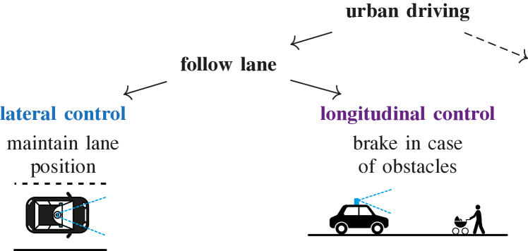
To effectively co-design a robotic platform, it is appropriate to create a functional decomposition of the platform’s task. The guiding example in this paper is that of an AV, but we argue that the same principle can be generalized to embodied intelligence. We consider as the main function urban driving (Fig. 1(a)). We zoom in on the follow lane function (parallel functions would be handle intersections, pick up passenger, etc). One can decompose lane-following into two more specific functions: lateral control (i.e., stay in a lane) and longitudinal control (i.e., accelerate and brake in presence of obstacles). For these two functions we provide a reasonably detailed analysis. Note that there is no limitation for our method to decompose a system into an arbitrary number of functions.
In the following we refer to “functions” (in the systems engineering nomenclature) as “tasks”, since the term “functions” clashes with co-design “functionalities”.
Task abstraction
The output of functional decomposition is a collection of sub-tasks, which in co-design can commonly be abstracted as MDPIs (Fig. 3(a)). In particular, embodied intelligence tasks share a common structure, constituted of task-specific functionalities, such as performance and system-level functionalities shared with other components such as scenarios/environments (e.g., time of the day, density of obstacles). Furthermore, we identified cost (in CHF), power (in W), computation effort (in op/s) and mass (in g) as the four main resources which “need to be paid” to achieve a particular desired task performance in any embodied intelligence scenario. These four resources are the result of a simplification and models can be refined at will, e.g., by distinguishing operation, maintenance and fixed costs, or by analyzing CPU and GPU computation separately.
From function decomposition to co-design diagrams
Given specific task abstractions, one can convert a functional decomposition diagram into a co-design diagram (Fig. 3(b)). To do so, the specific scenarios/environments are fed into each sub-task and a general task performance is assigned to the problem. In particular, the functional decomposition block has knowledge of the task decomposition logic and knows for each task performance level which combinations of performance levels are required. The resources required by the different sub-tasks are generated independently and then “summed”222Or, in general, an associative operation is applied, such as or +.. We note the compositionality property of this formalization: the resulting diagram has the same interface as that of a task, meaning that a composite task is a task.
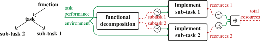
From data flow to co-design diagrams
To understand the co-design approach, one needs to distinguish logical dependencies and data-flow (Fig. 4). By considering logical dependencies (Fig. 4(a)), we realize that the purpose of a robotic task implementation is to provide decision making, which, to be produced, needs state information. The latter is estimated through sensing data, provided by a sensor. The actual data flow in robotic tasks develops in the reverse direction (Fig. 4(b)). Co-design diagrams are a formalization of logical dependencies and are not to be understood as signal-flow diagrams. In the following we present the formalization of the co-design problem of an AV, highlighting the properties of the monotone co-design theory.
III-B Modeling lateral control
We consider the task of lane-following as the combination of the lateral and longitudinal control tasks. In this paragraph we focus on the co-design of lateral control (Fig. 5). We explain each block of the diagram in turn, by describing its working principles and how to obtain its model.
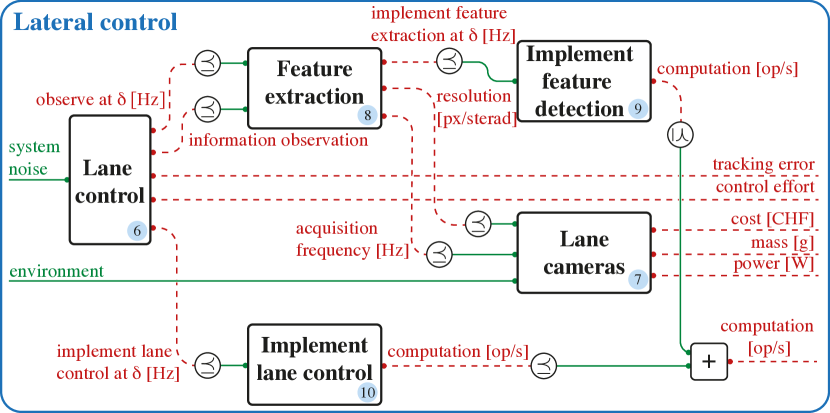
Block Lane Control: Given the task of the vehicle to align itself with the lane, we define the AV configuration as , where is the heading of the AV and is its relative lateral position with respect to the center of the lane. The desired lane-aligned configuration at time is denoted by and the control input is the steering torque . We assume that from the sensor we can have Gaussian observations of the state , where is white Gaussian noise with covariance . As we show in [22], this problem can be solved with LQG control, choosing to minimize the objective . This can be formalized as the lane control MDPI (Fig. 5), in which the functionality is the ability of the control to handle a given system noise and the resources are the needs to obtain the observations at a certain frequency with given precision and to implement the optimal control law at a specific frequency (in Hz), providing control effort and tracking error . The implementations the designer can choose are the different cost weights, parametrized by . Obtaining the model: We show in [22] how the nature of the problem allows to obtain the optimal solutions for the MDPI by solving specific Riccati equations.
Block Lane Cameras: We need to define a relation between the accuracy of the sensing and the physical sensors. Measurements are provided at a given frequency and with a specific resolution (in px/sterad) by lane cameras , which have a cost, mass and power consumption. Obtaining the model: This is obtained straight from camera catalogues.
Block Feature Detection: A feature detection algorithm processes the measurements providing the lane control MDPI with observations at a certain frequency and with a certain precision. Obtaining the model: This is the realm of photogrammetry. We need to answer questions such as “what resolution (in px/sterad) is needed to achieve a certain feature detection accuracy?”.
Blocks Algorithms Implementation: Finally, it is necessary to choose the implementation of the actual feature detection and lane control algorithms ( and ). For each of these we have an MDPI characterized by a catalogue of algorithms, each requiring different computation power. Obtaining the model: This is a benchmarking exercise. An excellent example of how to create benchmarking catalogues for algorithms, going as deep as to also search over the compiler flags, is given by SLAMBench [27] and the successive papers by Nardi and collaborators. For perception problems which cannot be adequately modeled by analytical photogrammetry relations, it also makes sense to not only vary implementation details (e.g., compiler flags) but also algorithm parameters. In that case, benchmarking would include the scope of the last two blocks together.
Entire lateral control diagram: The general lateral control co-design diagram (Fig. 1(b)) includes robustness to specific system noise and environment and requires the common resources cost, mass, power and computation power, together with tracking error and control effort, which will be important when implementing safety and control metrics. If the reader agrees that each block is an MDPI then their composition is an MDPI. One should already notice that the lateral control design problem involves the co-design of hardware and software components.
III-C Modeling longitudinal control
As highlighted above, lateral control can be modeled as a co-design problem using analytical solutions of optimal control problems. For the longitudinal control sub-task, however, we want to showcase the ability of our framework to handle cases in which co-design relations are not directly available in analytical form, to the point at which one has to rely on tools such as numerical simulation (Fig. 6). The AV is required to brake in time in the presence of obstacles and to guarantee a desired cruise speed. The AV is characterized by a dynamic performance , where is the maximum vehicle’s achievable speed and , are its maximum acceleration and deceleration. These parameters depend on the chosen vehicle type (e.g., on the propulsion system). The vehicle’s longitudinal dynamics are , , where and represent the vehicle’s acceleration and velocity.
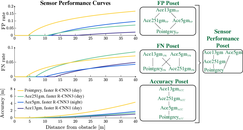
Block Longitudinal sensing: The AV is equipped with sensors, which provide obstacle detections along the road. It has already been observed that sensors can be ordered by their ability to discriminate states [28]. In our work, each sensor is characterized by its sensing performance, expressed as a tuple , where represent false positives (i.e., given an environment without obstacles, the probability of detecting one) and false negatives (i.e., assuming the presence of an obstacle, the probability of not detecting it) curves as a function of distance from the obstacle and with denoting the sensing accuracy (range) as a function of distance from the obstacle. These curves can be obtained is different ways, as explained in Section IV. Note that to consider the curves as functionalities in the longitudinal sensing MDPI , we compare them in posets using the point-wise order, and combine the posets by taking their product, resulting in the sensor performance poset. In Fig. 7, one can see examples of these curves together with the corresponding Hasse diagrams for the posets. The Hasse diagram can be understood as follows. In the false positives poset, sensor Pointgrey is dominated by Ace5gm, Ace251gm and, by transitivity, by Ace13gm. The detections also depend on the environment in which the task needs to be solved. This includes the time of the day as well as the density of obstacles on the road. Furthermore, a sensor provides measurements at a certain acquisition frequency and has specific latency (in s), cost, mass and power. Obtaining the model: One obtains sensor specifications from catalogues and detection properties from benchmarking.
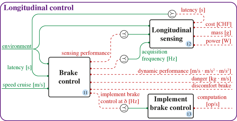
Block Brake control: Based on the generative model of the measurements, we produce a Bayesian estimate of the probability of having a pedestrian at each distance and denote it by . Because it is not possible to derive a closed form solution for this POMDP, we choose the parametrized control law in Algorithm 1.
Doing so, we can write the brake control problem as an MDPI (Fig. 6) in which functionalities are the provided cruise speed (i.e., the performance, in km/h) and the handled sensing latency and environment. The resources are the sensing performance, the sensing acquisition frequency, the computation power needed to execute the control law and the dynamic performance of the vehicle. Furthermore, we measure the performance of the longitudinal control action by means of discomfort and danger, defined as follows. Given a time horizon , discomfort is expressed as and penalizes changes in acceleration [29]. Danger captures both the probability and the impact of failures and is expressed as the product of the probability of hitting an obstacle and the momentum of the collision (in kgm/s). Obtaining the model: Given the sensing model and the controller parameters, the brake control MDPI can be modeled by running numerical simulations. This approach has two fundamental advantages. First, the simulations can be run in parallel, as they do not depend on each other. Second, the general co-design optimization can be run with incomplete simulation results, obtaining reduced levels of accuracy for the co-design solutions. It can actually be shown that the accuracy of the solutions of the co-design problem is monotone with the number of simulations one has [30]. Leveraging such properties is important material for future research.
Block implementation brake control: Brake control needs to be actually implemented (Fig. 6). Obtaining the model: Different implementations of the control algorithms have different properties in terms of control update frequency and required computational effort
Entire longitudinal control diagram: By interconnecting the aforementioned blocks, one obtains the co-design diagram for the longitudinal control of an AV (Fig. 6). The general longitudinal control co-design diagram (Fig. 1(b)) features the first loop through latency and is subject to the environment and desired cruise speed and requires cost, mass, power, dynamic performance, danger, discomfort and computation.
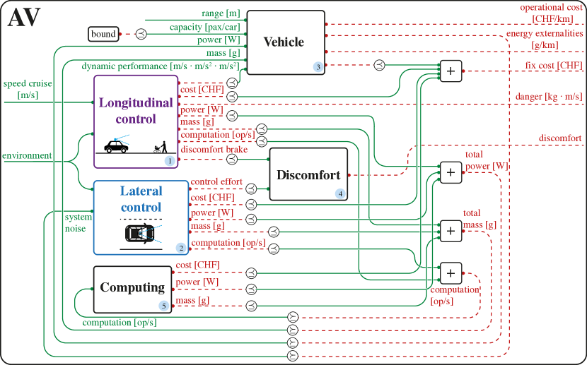
III-D Composing the full diagram
In the previous sections we detailed the modeling of the lateral control and longitudinal control MDPIs. Following the principle of functional decomposition, we can now interconnect these two components with the rest of the system, obtaining the general co-design diagram reported in Fig. 1(b). Block Computing Unit: This problem includes the design of the computing unit (Example 6), which needs to provide computation power required by all the processes we have presented and which requires power and has a mass and a cost. As illustrated in Fig. 1(b), the feedback of computation power constitutes the second feedback loop of our co-design diagram. Obtaining the model: The computing unit can be modeled through computer catalogues.
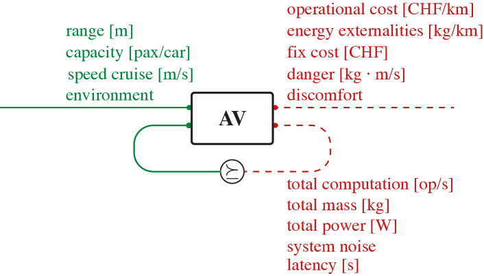
Block Vehicle: Furthermore, the general co-design diagram includes the vehicle MDPI (Fig. 1(b)), which represents the mechanical part of the system. This can be formulated as a MDPI which provides certain dynamic performance and range (in m) and has a certain capacity (in pax/car), requiring both operational and fix costs and energy externalities (in g/km). Specifically, the vehicle has the ability to provide power which allows computing, longitudinal control and lateral control to happen (third feedback loop) and to carry extra mass, arising from the sum of the mass of the sensors and computing unit (fourth feedback loop). Both increased mass and power reduce the vehicle range. Each vehicle is characterized by a system noise, which is fed back into the lateral control block (fifth feedback loop). Obtaining the model: This model can be extracted from catalogues (e.g., by switching propulsion systems and chassis).
Block Discomfort: Finally, a discomfort MDPI (Fig. 1(b)) joins the discomfort arising from the longitudinal control and from the lateral control (in terms of control effort) to produce the discomfort performance metric. Obtaining the model: One can combine discomfort metrics arising from lateral and longitudinal controls using different assumptions, generating particular discomfort models.
General AV diagram: We can represent the MDPI shown in Fig. 1(b) in the canonical form, as shown in Fig. 8. The meaning of the canonical form is captured by the categorical trace operator , where is the co-design problem with loops and is the co-design problem with no loops. This provides an upper bound for the complexity of the solution algorithm, as shown in [24, Proposition 5]. The solver (working principle of which is explained in detail in [24]) will solve the problem by creating a chain in the poset of antichains of , where the latter represents the product poset containing the five resources which are fed back.
Discussion
We note three points. First, the approach described in this section is applicable to a large variety of systems in engineering, and describes a natural way to incorporate trade-offs in design decisions. Second, the modular and compositional properties of this tool allow different designers to focus on specific blocks, and to then intuitively interconnect the MDPI. Finally, no specific mention of uncertainty was made, but the nature of the proposed framework allows for an extension in this direction, as explained in [30].
IV Co-design Results
In this section we showcase the abilities of the proposed framework to solve the co-design problem of an AV. By considering the MDPI proposed in Fig. 1(b), we optimize the design of an AV by means of cost, danger, discomfort, emissions, robustness to environment and cruise speed. In particular, the design options, listed in Table I, include the selection of longitudinal and lateral sensors, control parameters, vehicles, computers and detection algorithms. Note that the co-design optimization performed in this work is solved by a framework based on a formal language333Visit co-design.science for further information and future code release. The solution techniques and their complexity are described in [24] and in the talk at https://bit.ly/3ellO6f..
Remark.
The following case study does not need to be analyzed quantitatively but qualitatively: our contribution lies in the formalization of the meta-models and is not about numbers. We look forward to working with experts in each specific field to get more accurate data. Also, the complexity for this kind of optimization problems is described in [24, Proposition 5].
We assume obstacles to be distributed following a spatial Poisson process and generate sensor performance curves for the 16 sensors listed in Table I (see Fig. 7 for an example) using the results from [31, 32]. The authors of [31] compare the pedestrian camera detection performance during day- and night-time at two different operating points of a Faster R-CNN object detection algorithm. The performance in terms of recall and precision is investigated against object distances and object heights in px. We leveraged these results to interpolate the performance of the object detection with different sensors, using sensor resolution and angle of view [33]. For the camera accuracy we used the stereo depth error for a fixed baseline, assuming monocular camera depth estimation [34, 35]. Lidar sensor performance curves are generated using the results of [32], who show that the 3D pedestrian detection efficiency decreases as the distance between lidar and objects increases. This effect can be explained by the decrease in number of reflected points available per obstacle as the distance increases. Recall and precision performances are presented for different distances for three different algorithms (KDE-based, STM-RBNN and STM-KDE). The authors trained and validated their models on the KITTI dataset [36], originating from measurements of a Velodyne HDL-64 lidar. We estimated the measurement points per object at different distances and used them to interpolate for other lidars, generating curves similar to the ones presented in [37]. Finally, we assumed a constant accuracy for the lidars, extracting it from sensor catalogues. Note that our framework can accommodate arbitrary sensor curves, enabling us to test non-existent sensor performances as well. Given this setting, we simulated both the longitudinal and lateral control of the AV, creating numerical catalogues for the MDPI. As previously explained, these simulations can be run in parallel, and build a database on which the solver can operate.
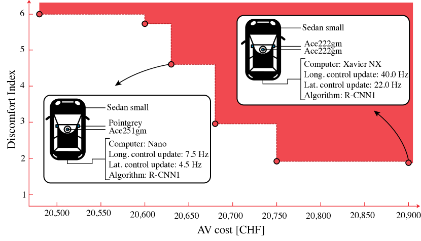
Solutions which guarantee a certain speed (Fig. 9(a))
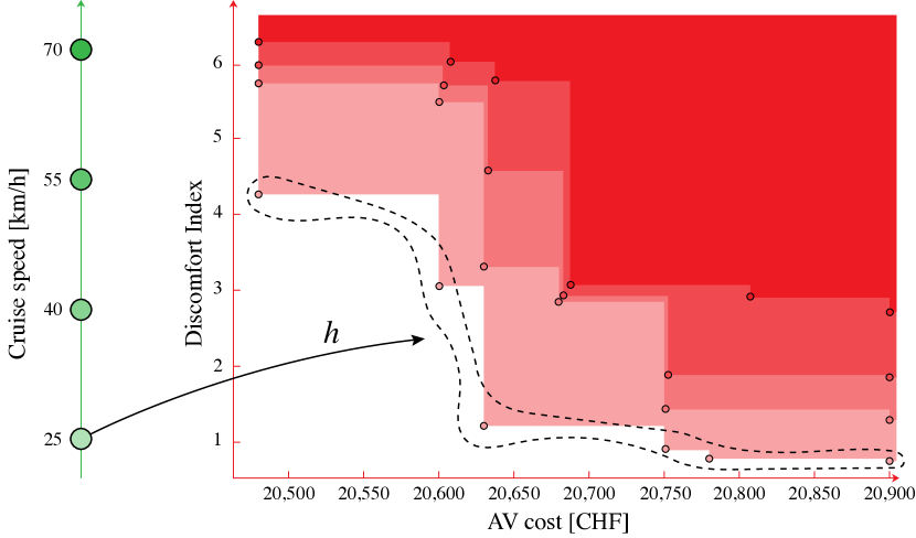
We assume an obstacle density of 5.0 obstacles/km during the day and query the optimal design solutions which enable the AV to reach 55.0 km/h (Fig. 9(a)). The dashed line represents the antichain of optimal solutions for the co-design problem, consisting of cost and discomfort. These solutions are not comparable, meaning that there is no instance which yields simultaneously lower discomfort and cost. In solid red we represent the upper set of resources. Attached, one can find selected design implementations, corresponding to specific optimal solutions. In general, as the budget for the AV increases, one is able to reduce the discomfort. For instance, with a cost of of 20,630 CHF one can obtain a discomfort index of 4.49, buying a small Sedan, equipping it with Pointgrey lateral cameras and an Ace251gm longitudinal camera paired with the R-CNN1 detection algorithm, together with a Nano computer. The vehicle is controlled at 7.5 Hz longitudinally and at 4.5 Hz laterally. Notably, investing only 150 CHF more per AV improves the discomfort by 250 %, requiring a Xavier NX computing unit, which controls the AV at 40.0 Hz and 22 Hz longitudinally and laterally, respectively, using measurements of two Ace222gm cameras.
Monotonicity of the AV MDPI (Fig. 9(b))
We consider increasing cruise speeds and analyze the evolution in trade-offs in cost and discomfort. As can be gathered from Fig. 9(b), we query the co-design solver for multiple performances, given arbitrary environments (here 5.0 obstacles/km during the day). Specifically, for each functionality, we compute the map which maps to the minimum antichain of resources which provide it (Def. 9). Note that by increasing the desired cruise speed, one increases the required resources, as can be observed from the dominating upper sets in increasing red tonality. Given such trade-offs and the discrete nature of our tool, one can reason about the MDPI by distinguishing the desired objectives.
| Variable | Options | Source |
| Vehicle | Sedan Small, Large, BEV, SUV, Minivan | [38] |
| Computers | Xavier, AGX, Nano, XavierNX | [39] |
| Control update | Brake: 1.0-50.0 Hz, Lane: 0.1-100.0 Hz | - |
| Sensors | ||
| Lidars | Puck, HDL32E/64E | [40] |
| OS032/64/128, OS232/64/128 | [41] | |
| Cameras | Ace251gm/222gm/13gm/5gm/15um | [42] |
| Flir Pointgrey | [43] | |
| Algorithms | Cameras: R-CNN1, R-CNN3 | [31, 37] |
| Lidars: KDE, STM-RBNN, STM-KDE | [32] |
V Conclusions
This article leveraged a monotone theory of co-design to formulate and solve the optimal co-design of embodied intelligence platforms. We have shown how we can employ principles of functional decomposition to formalize embodied intelligence tasks as interconnected co-design problems. This work shows for the first time the ability of this monotone co-design theory to describe design problems arising from analytical relations, simulations and catalogues. We demonstrate the potential of our approach by modeling an AV, composed of heterogeneous components, usually modeled using different, compartmentalized techniques.
Outlook
The methods we propose are intuitive to understand and use, and promise to unite different engineering disciplines under a common goal. Our vision is the one of compositional engineering, which would allow one to describe and co-design systems from signals [44] all the way up to control systems [22] and mobility networks [45, 46, 47]. In particular, we are interested in leveraging the complexity properties described in [24], showcasing the compositional properties of our framework, by interconnecting the co-design problem of an AV with the co-design problem of a urban mobility system. There, the MDPI reported in Fig. 8 would become part of a larger diagram of interconnected MDPIs, and one could get design strategies at a further abstraction level.
References
- [1] J.-P. Merlet, “Optimal design of robots,” 2005.
- [2] A. Spielberg, B. Araki, C. Sung, R. Tedrake, and D. Rus, “Functional co-optimization of articulated robots,” in 2017 IEEE International Conference on Robotics and Automation (ICRA). IEEE, 2017, pp. 5035–5042.
- [3] M. Lahijanian, M. Svorenova, A. A. Morye, B. Yeomans, D. Rao, I. Posner, P. Newman, H. Kress-Gazit, and M. Kwiatkowska, “Resource-performance tradeoff analysis for mobile robots,” IEEE Robotics and Automation Letters, vol. 3, no. 3, pp. 1840–1847, 2018.
- [4] S. Seok, A. Wang, M. Y. Chuah, D. J. Hyun, J. Lee, D. M. Otten, J. H. Lang, and S. Kim, “Design principles for energy-efficient legged locomotion and implementation on the mit cheetah robot,” IEEE/ASME Transactions on Mechatronics, vol. 20, no. 3, pp. 1117–1129, 2014.
- [5] J. M. O’Kane and S. M. LaValle, “Comparing the power of robots,” The International Journal of Robotics Research, vol. 27, no. 1, pp. 5–23, 2008.
- [6] S. Karaman and E. Frazzoli, “High-speed motion with limited sensing range in a poisson forest,” in 2012 IEEE 51st IEEE Conference on Decision and Control (CDC). IEEE, 2012, pp. 3735–3740.
- [7] G. Bravo-Palacios, A. Del Prete, and P. M. Wensing, “One robot for many tasks: Versatile co-design through stochastic programming,” IEEE Robotics and Automation Letters, vol. 5, no. 2, pp. 1680–1687, 2020.
- [8] A. Q. Nilles, D. A. Shell, and J. M. O’Kane, “Robot design: Formalisms, representations, and the role of the designer,” arXiv preprint arXiv:1806.05157, 2018.
- [9] F. Ramos, A. S. Vázquez, R. Fernández, and A. Olivares-Alarcos, “Ontology based design, control and programming of modular robots,” Integrated Computer-Aided Engineering, vol. 25, no. 2, pp. 173–192, 2018.
- [10] A. A. C. Collin, “A systems architecture framework towards hardware selection for autonomous navigation,” Ph.D. dissertation, Massachusetts Institute of Technology, 2019.
- [11] V. Gupta, T. H. Chung, B. Hassibi, and R. M. Murray, “On a stochastic sensor selection algorithm with applications in sensor scheduling and sensor coverage,” Automatica, vol. 42, no. 2, pp. 251–260, 2006.
- [12] S. Joshi and S. Boyd, “Sensor selection via convex optimization,” IEEE Transactions on Signal Processing, vol. 57, no. 2, pp. 451–462, 2008.
- [13] Y. Zhang and D. A. Shell, “Abstractions for computing all robotic sensors that suffice to solve a planning problem,” in 2020 IEEE International Conference on Robotics and Automation (ICRA). IEEE, 2020, pp. 8469–8475.
- [14] D. A. Shell, J. M. O’Kane, and F. Z. Saberifar, “On the design of minimal robots that can solve planning problems,” IEEE Transactions on Automation Science and Engineering, pp. 1–12, 2021.
- [15] A. Collin, A. Siddiqi, Y. Imanishi, Y. Matta, T. Tanimichi, and O. de Weck, “A multiobjective systems architecture model for sensor selection in autonomous vehicle navigation,” in International Conference on Complex Systems Design & Management. Springer, 2019, pp. 141–152.
- [16] B. Guo, O. Karaca, T. Summers, and M. Kamgarpour, “Actuator placement for optimizing network performance under controllability constraints,” in 2019 IEEE 58th Conference on Decision and Control (CDC), 2019, pp. 7140–7147.
- [17] D. Golovin, M. Faulkner, and A. Krause, “Online distributed sensor selection,” in Proceedings of the 9th ACM/IEEE International Conference on Information Processing in Sensor Networks, 2010, pp. 220–231.
- [18] T. Tanaka and H. Sandberg, “Sdp-based joint sensor and controller design for information-regularized optimal lqg control,” in 2015 54th IEEE Conference on Decision and Control (CDC). IEEE, 2015, pp. 4486–4491.
- [19] S. Tatikonda and S. Mitter, “Control under communication constraints,” IEEE Transactions on automatic control, vol. 49, no. 7, pp. 1056–1068, 2004.
- [20] U. Rosolia, A. Singletary, and A. D. Ames, “Unified multi-rate control: from low level actuation to high level planning,” arXiv preprint arXiv:2012.06558, 2020.
- [21] V. Tzoumas, L. Carlone, G. J. Pappas, and A. Jadbabaie, “Lqg control and sensing co-design,” IEEE Transactions on Automatic Control, 2020.
- [22] G. Zardini, A. Censi, and E. Frazzoli, “Co-design of autonomous systems: From hardware selection to control synthesis,” in 2021 20th European Control Conference (ECC), 2021.
- [23] B. A. Davey and H. A. Priestley, Introduction to lattices and order. Cambridge university press, 2002.
- [24] A. Censi, “A mathematical theory of co-design,” arXiv preprint arXiv:1512.08055, 2015.
- [25] ——, “A class of co-design problems with cyclic constraints and their solution,” IEEE Robotics and Automation Letters, vol. 2, no. 1, pp. 96–103, 2016.
- [26] B. Fong and D. I. Spivak, An invitation to applied category theory: seven sketches in compositionality. Cambridge University Press, 2019.
- [27] L. Nardi, B. Bodin, M. Z. Zia, J. Mawer, A. Nisbet, P. H. J. Kelly, A. J. Davison, M. Luján, M. F. P. O’Boyle, G. D. Riley, N. P. Topham, and S. B. Furber, “Introducing slambench, a performance and accuracy benchmarking methodology for SLAM,” in IEEE International Conference on Robotics and Automation, ICRA 2015, Seattle, WA, USA, 26-30 May, 2015. IEEE, 2015, pp. 5783–5790. [Online]. Available: https://doi.org/10.1109/ICRA.2015.7140009
- [28] S. M. LaValle et al., Sensing and filtering: A fresh perspective based on preimages and information spaces. Now Publishers, 2012.
- [29] A. Reschka, J. R. Böhmer, F. Saust, B. Lichte, and M. Maurer, “Safe, dynamic and comfortable longitudinal control for an autonomous vehicle,” in 2012 IEEE Intelligent Vehicles Symposium. IEEE, 2012, pp. 346–351.
- [30] A. Censi, “Uncertainty in monotone codesign problems,” IEEE Robotics and Automation Letters, vol. 2, no. 3, pp. 1556–1563, 2017.
- [31] M. Braun, S. Krebs, F. Flohr, and D. M. Gavrila, “Eurocity persons: A novel benchmark for person detection in traffic scenes,” IEEE transactions on pattern analysis and machine intelligence, vol. 41, no. 8, pp. 1844–1861, 2019.
- [32] K. Liu, W. Wang, and J. Wang, “Pedestrian detection with lidar point clouds based on single template matching,” Electronics, vol. 8, no. 7, p. 780, 2019.
- [33] R. Hartley and A. Zisserman, Multiple view geometry in computer vision. Cambridge university press, 2003.
- [34] D. Gallup, J.-M. Frahm, P. Mordohai, and M. Pollefeys, “Variable baseline/resolution stereo,” in 2008 IEEE conference on computer vision and pattern recognition. IEEE, 2008, pp. 1–8.
- [35] T. Zhou, M. Brown, N. Snavely, and D. G. Lowe, “Unsupervised learning of depth and ego-motion from video,” in Proceedings of the IEEE Conference on Computer Vision and Pattern Recognition, 2017, pp. 1851–1858.
- [36] A. Geiger, P. Lenz, C. Stiller, and R. Urtasun, “Vision meets robotics: The kitti dataset,” International Journal of Robotics Research (IJRR), 2013.
- [37] B. Borgmann, M. Hebel, M. Arens, and U. Stilla, “Pedestrian detection and tracking in sparse mls point clouds using a neural network and voting-based approach,” ISPRS Annals of the Photogrammetry, Remote Sensing and Spatial Information Sciences, vol. 2, pp. 187–194, 2020.
- [38] A. A. Association et al., “Aaa’s your driving costs,” 2018.
- [39] NVIDIA. (2020) Nvidia products. Available online: https://www.nvidia.com.
- [40] Velodyne. (2020) Velodyne lidars. Available online: https://velodynelidar.com.
- [41] Ouster. (2020) Ouster lidars. Available online: https://ouster.com.
- [42] Basler. (2020) Basler cameras. Available online: https://www.baslerweb.com.
- [43] Flir. (2020) Flir cameras. Available online: https://www.flir.com.
- [44] G. Zardini, D. I. Spivak, A. Censi, and E. Frazzoli, “A compositional sheaf-theoretic framework for event-based systems,” in 3rd Annual International Applied Category Theory Conference (ACT 2020), 2020.
- [45] G. Zardini, N. Lanzetti, M. Salazar, A. Censi, E. Frazzoli, and M. Pavone, “On the co-design of av-enabled mobility systems,” in Proc. IEEE Int. Conf. on Intelligent Transportation Systems, Rhodes, Greece, Sept. 2020.
- [46] G. Zardini, N. Lanzetti, A. Censi, E. Frazzoli, and M. Pavone, “Co-design to enable user-friendly tools to assess the impact of future mobility solutions,” 2020.
- [47] G. Zardini, N. Lanzetti, M. Pavone, and E. Frazzoli, “Analysis and control of autonomous mobility-on-demand systems: A review,” Annual Review of Control, Robotics, and Autonomous Systems, 2021.