REX: X-ray experiment on the Water Recovery Rocket
Abstract
This paper presents Rocket Experiment (REX) that was part of a dual-payload rocket campaign for NASA’s sounding rocket Black Brant IX with water recovery technology. This mission was a suborbital sounding rocket flight that was launched and recovered on April 4, 2018 and targeted the Vela supernova remnant. The purpose of REX was to classify the Technology Readiness Level of onboard devices designed for space applications. The devices were two wide-field X-ray telescopes consisting of a combination of Lobster-Eye (LE) optics with an uncooled Timepix detector (256 256 @ ), and additional sensors. The first telescope uses a two-dimensional combination of LE modules with a focal length of and a Field of View (FOV) of 1.0 1.2 and operates in the energy range of 3 – 60 . The second telescope was a one-dimensional LE with a focal length of and a FOV of 2.7 8.0 for the energy range 3 – 40 . The X-ray telescopes were supplemented by a camera in the visible spectrum with 1,280 1,024 resolution, which was used to obtain images of the observed sources and to verify the resulting pointing of the rocket carrier. Other devices also include infrared array sensors and inertial measurement units tested for future small satellite missions. The data handler and communication system were built using the Robot Operating System, and both the system and the electronics were deployed and operated in-flight. The hardware was successfully recovered after the launch and the data were extracted.
keywords:
Sounding rocket , X-ray , Lobster-Eye , Radiation imaging1 Introduction
Sounding rockets, a type of Suborbital rockets, provide a low-cost observing platform for carrying instruments for scientific and educational purposes, as well as for rapid technology validation. This is very advantageous for testing the Technology Readiness Level (TRL) of space instrumentation without the need for expensive boosters and advanced telemetry systems. Therefore, the price of the launch is lower than for satellite missions. The disadvantage of using suborbital rockets is in the limited experiment time, which is usually 5 – 20 . Nevertheless, they are still useful for verification of technologies in space which do not require a long experimental time. A major consideration for the TRL of devices used in space is not only the capability of working in vacuum, extreme temperatures, temperature changes, and radiation, but also the ability to survive the violent conditions during launch and booster separation [1].
Aside from TRL verification, sounding rockets can also be used for scientific purposes. One example of a scientific mission was the CHAMPS mission launched in October, 2011. Two rockets were used to detect and measure the density and size distribution of meteoritic smoke particles in the upper atmosphere [2]. Another mission was focused on the examination of the Sun’s atmosphere and was launched in 2009 by NASA’s sounding rocket. Its goal was the research of the helium amount and how the solar wind originated and accelerated [3]. The last mentioned example is from the RockOn! series of sounding rocket missions carrying experiments developed by the students during NASA supported workshops111https://www.nasa.gov/wallops/2019/feature/nasa-launches-student-experiments-to-space-on-a-suborbital-rocket222https://spacegrant.colorado.edu/national-programs/rockon-home. Rockets were launched from Wallops Flight Facility in Virginia regularly since 2008 [4, 5].
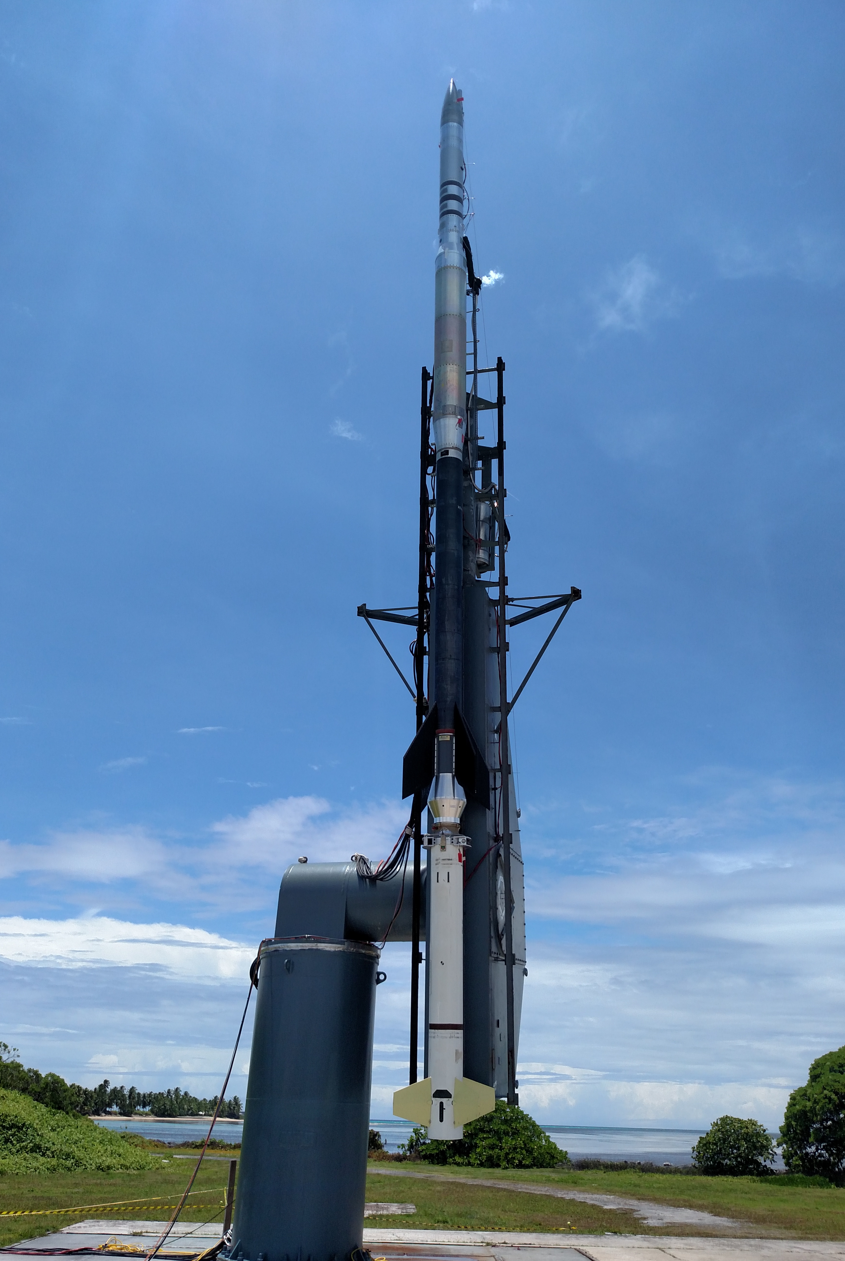
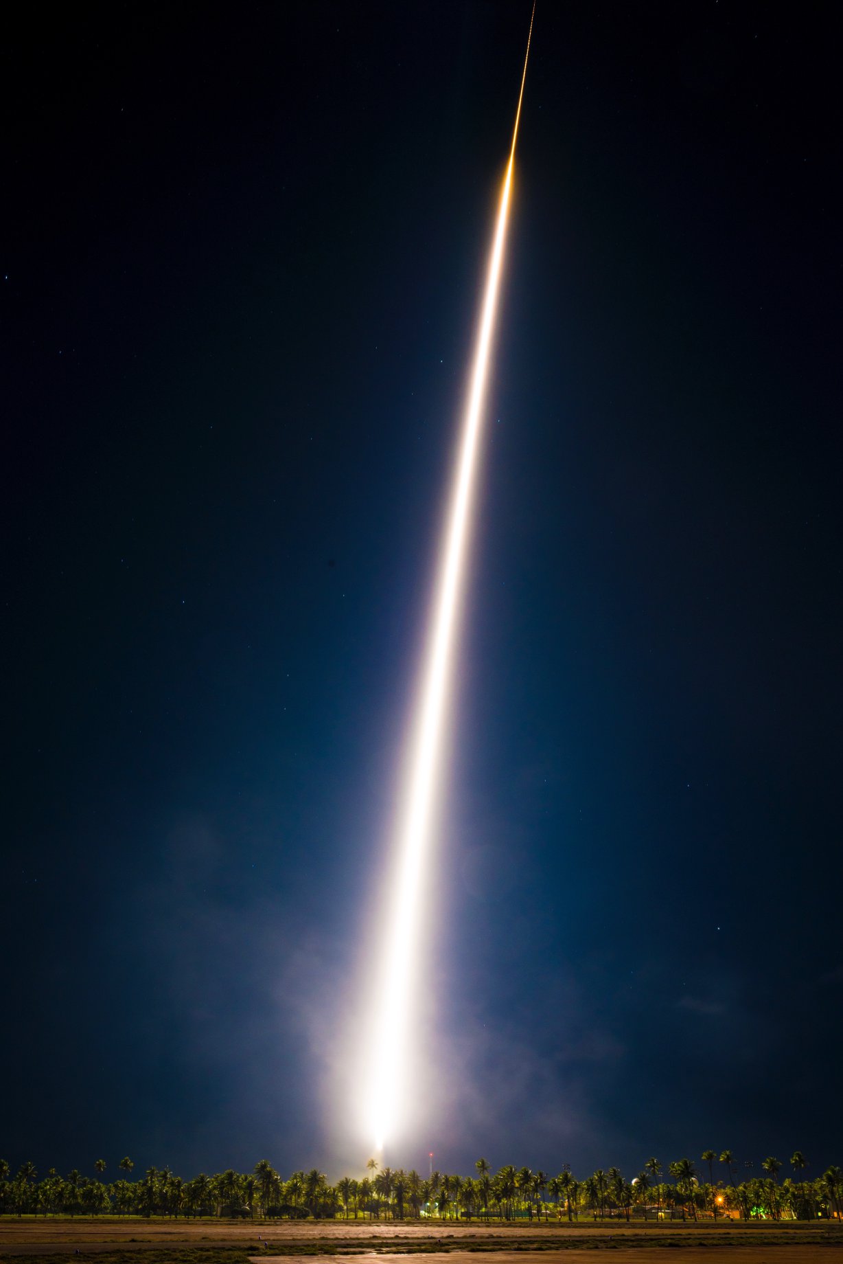
The suborbital mission described in this manuscript was a two-payload campaign carried by the NASA’s sounding rocket with water recovery technology for science payloads which was launched from the Kwajalein Atoll in the Marshall Islands on April 4, 2018. Figure 1 shows photos from the launch date.
The observation of the Vela Supernova Remnant (SNR) was the primary scientific astrophysical target of this sub-orbital experiment. The Vela SNR is a shell-type remnant located in the southern constellation Vela at a distance of approx. [6]. This source is Type II and it exploded approximately 11,000 – 12,300 years ago. The centre of the Vela SNR is formed by a neutron star with a strong magnetic field, with a mass close to our Sun and a diameter of approx. [7] (the apparent diameter of [8]). Due to the apparent size of the object and high surface brightness, this SNR is a frequent source of observation and testing of equipment for both sounding rockets [9, 10, 11] and space telescopes [12, 13]. In addition to scientific observation, the mission aims at an important technological goal, namely the suborbital flight verification of scientific payloads such as the Multi-Foil Optics (MFO) type of LE with a Timepix pixel detector [14], and X-ray reflection gratings with a hybrid Complementary Metal–Oxide–Semiconductor (CMOS) detector.
The sounding rocket was prepared by the Pennsylvania State University (PSU) together with the main measuring instrument — a soft X-ray grating spectrometer (bandpass 0.25 – 0.75 ) named the Water Recovery X-ray Rocket (WRXR) payload. The spectrometer consisted of a mechanical collimator, X-ray reflection gratings, grazing incidence mirrors, and a hybrid CMOS detector. In-depth description of the mission goals and the WRXR payload can be found in [8, 15, 16, 17].
The second payload — the REX — was prepared by the Czech team and contained two sets of MFO in combination with the Timepix detector, which formed two separate X-ray telescopes. The first of the REX telescopes consists of two LE modules in the Schmid’s arrangement [18, 19] which covered a FOV of 1.0 1.22 deg in the energy range of 3 – 60 . The second telescope has a single one-dimensional (1D) LE module [20, 21] with a field of view of 2.75 8.0 for the energy range 3 – 40 keV. Moreover, the payload was equipped with additional sensors: Ximea camera for visible spectrum with the resolution of 1,280 1,024 , an infrared (IR) sensor array and an Inertial Measurement Unit (IMU). A photo of the payload is shown in Figure 2 with the WRXR on top and the REX on the bottom.
2 REX instrument description
The REX payload consisted of two main parts: the optics modules including sensors, and a hermetically sealed electronics box. An airtight bulkhead separated both parts and they were electrically connected via a vacuum feedthrough. The payload was also connected to a rocket interface panel via another vacuum feedthrough.
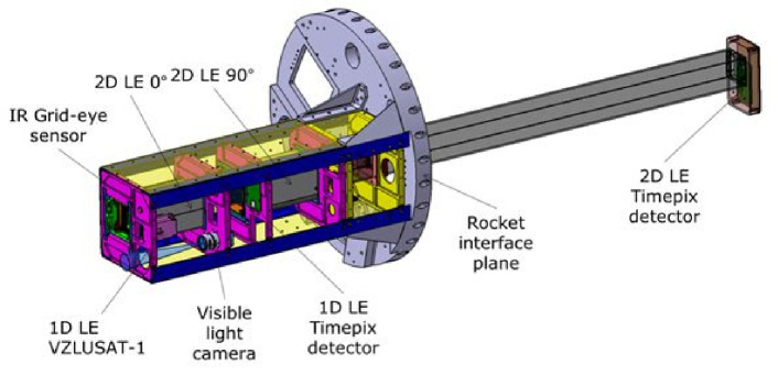
The optics and sensors section contained all the sensors and detectors except for the IMU, which was placed in the hermetic box. The sensor section was designed as hermetically sealed in order to hold an artificial low-pressure atmosphere to prevent liquid condensation during launch. The visible-light camera was used alongside the X-ray telescopes as well as the IR sensor array. A carbon-fiber baffle covered the optical path between the optic modules and Timepix detectors to avoid side rays. A schematic of the payload is shown in Figure 3.
The hermetic box contained NiCd batteries and switching power supply electronics with DC/DC converters for powering the devices during the entire duration of the experiment (approx. 2 hours). Two on-board Odroid-XU4 ARM computers managed the sensors and miscellaneous electronics provided an interface with the rocket. Each of the computers controlled a single Timepix detector (one per telescope), and the rest of the sensors were evenly distributed between the computers. Mission software using Robot Operating System (ROS)333http://ros.org was developed to operate and control the entire experiment. ROS is a widely adopted open-source middleware for the integration of sensors and data processing algorithms for autonomous systems. Simultaneously, an operating interface for Timepix detectors in ROS was developed under the name Rospix444http://github.com/rospix/rospix [22].
2.1 X-ray telescope based on Lobster-Eye optics and Timepix detector
The REX experiment consisted of two LE telescopes designed by Czech Technical University in Prague (CTU), manufactured by Rigaku Innovative Technologies (RITE), a two-dimensional (2D) in Schmidt’s arrangement and a 1D Lobster-Eye optics. Table 1 presents all the parameters of the optics: the coating of the mirror layers, the focal length or FOV and the physical position of the module in the experiment. The 1D LE optics has the same parameters as an identical copy used in our previous successful mission on the nanosatellite VZLUSAT-1 [7, 23].
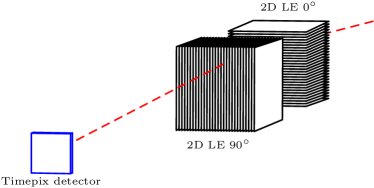
The position of both 1D and 2D telescopes are visualised in Figure 3. The 2D telescope contained two 1D optical modules placed in series. The modules were mutually rotated by along their optical axes to form a 2D optical system. Figure 4 shows an illustration of the 2D system configuration. A Timepix detector was placed from the front aperture in the focal plane of the 2D system. The 1D telescope was placed alongside the 2D, with another Timepix detector in the focal plane. The focal distance of the 1D was and the system contains only one optical module and thus the values for vertical dimension are void.
| 1D | 2D | |
| Module centre position (horizontal) | ||
| Module centre position (vertical) | - | |
| Focal length (horizontal) | ||
| Focal length (vertical) | - | |
| Field of view (horizontal) | ||
| Field of view (vertical) | ||
| (limited by housing) | ||
| Mirror thickness | ||
| Mirror spacing | ||
| Mirror dimension | 60 25 | 150 75 |
| Number of mirrors | 56 | 2 47 |
| Reflective surface | Au | Au |
| Angular resolution (horizontal) | ||
| Angular resolution (vertical) | - |
2.1.1 Simulating the optical systems
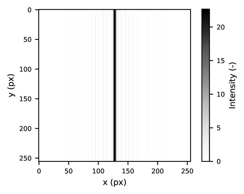
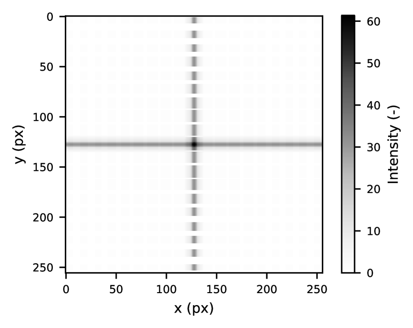
The Vela X-1 pulsar produces a flux of in the energy range of 4 – 25 [24] to the input aperture of each optic. For example, the Point Spread Function (PSF) can be used with a combination of two 1D Lobster-Eye optics for higher efficiency of the telescope, which leads to higher photon flux on the detector and thus in combination with a coded mask leads to a faster identification of events in the sky as is proposed in [25]. Figures 5 and 6 show simulated results of detector images where the optics have 100 reflectivity and the detector 100 quantum efficiency.
2.1.2 Timepix detector
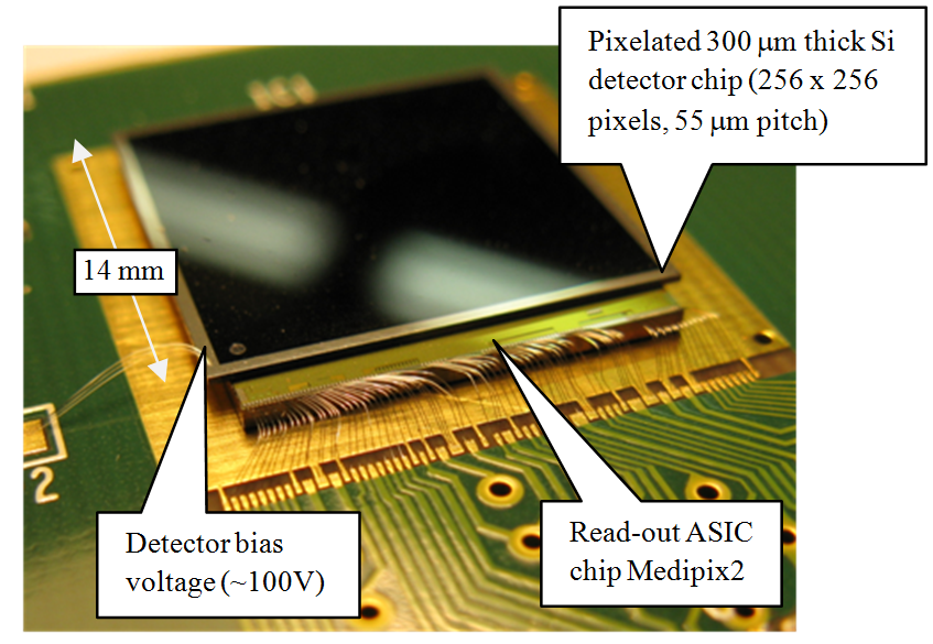
The Timepix detector [14] was used as an X-ray detector for the REX experiment. This hybrid silicon pixel detector developed at CERN consisted of a high-density matrix of 256 256 sensitive pixels with a pixel pitch of , and the total sensitive area of the detector was 14.1 14.1 . The Timepix sensor (see Figure 7) consists of two parts: the first part is the semiconductor detection layer ( silicon in this case used for the energy range of 3 – 60 ), which is bump bonded to the second part, an Application-Specific Integrated Circuit (ASIC) readout chip containing preamplifier, Analog-to-Digital Converter (ADC), and a counter for each pixel. Data from the sensor can be read out as fast as 100 images per second (depending on the accompanying hardware interface [26, 27, 28, 29]), which makes it ideal for particle tracking applications. On the other hand, long acquisition times on the order of minutes are possible, thanks to the sensor’s noise-less output. The matrix of all 65,535 pixels can be equalized for a given energy threshold which makes the sensor filter out events with lower energy than the threshold. Thus it is possible to record even single-photon events while measuring their energy.
Timepix has already been extensively tested in space [30], e.g., onboard the International Space Station [31, 32], the Proba-V satellite [33], CubeSat VZLUSAT-1 [34, 35, 23], TechDemoSat-1 [36, 37], and RISESAT [38]. Two spare detectors from the RISESAT project were used for the REX payload.
2.2 Camera for the visible spectrum
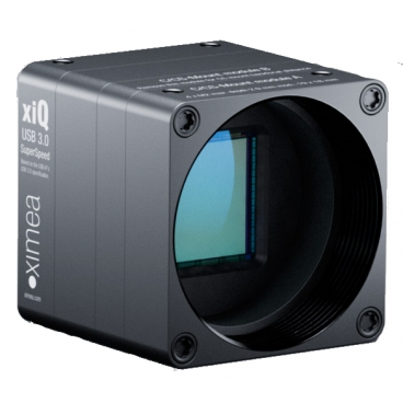
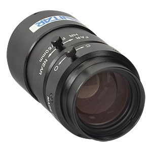
The camera system for the visible spectrum was employed to verify the REX’s target pointing in addition to the primary Attitude Determination and Control System (ADCS) of Black Brant IX rocket. Verification of the small, cheap, and uncooled industrial class CMOS camera was the secondary purpose of this system, as it is considered for the future CubeSat missions. The camera system was based on the Ximea MQ013CG-E2 module with a small size (26 26 26 ) and low weight (). The camera has a 1/1.8” CMOS sensor with native resolution. The camera module was equipped with ThorLabs MVL50M23 lens, with a focal length of , offering a field of view approximately . Figure 8(b) shows the camera module and the used lens. The low power consumption and the aluminum camera case attached to the massive rocket mechanical structure mitigated the possibility of the camera overheating in vacuum. An absence of plastic materials in the camera body avoided the pollution of the telescopes by material outgassing. The USB3 interface and the availability of drivers for the ROS made it easier to implement the camera control software in the Odroid on-board computer. The camera outputs uncompressed RAW images which allow post-processing of captured images after the rocket’s recovery.
2.3 Additional sensors
The infrared array sensor Grid-EYE AMG88 (8 8 resolution) was added to the REX payload as a technology demonstrator of Earth horizon detection. It could be used as one of the inputs to ADCS algorithms of a small CubeSat satellites. Furthermore, we employed an off-the-shelf IMU, the MPU6000. It is a miniature low cost 3-axis Micro-electro-mechanical System (MEMS) accelerometer and gyroscope, widely used in commercial electronics and robotics. As this class of electronics is not dedicated for space application, the main reason for using it in this mission was to test the capability of the sensor to survive the hard conditions of the rocket launch. The possibility of its future usage for recognition of flight phases and experiments triggering as well as future usage in attitude determination and control systems of small satellites will be examined.
3 Experimental results
3.1 Launch event and payload recovery
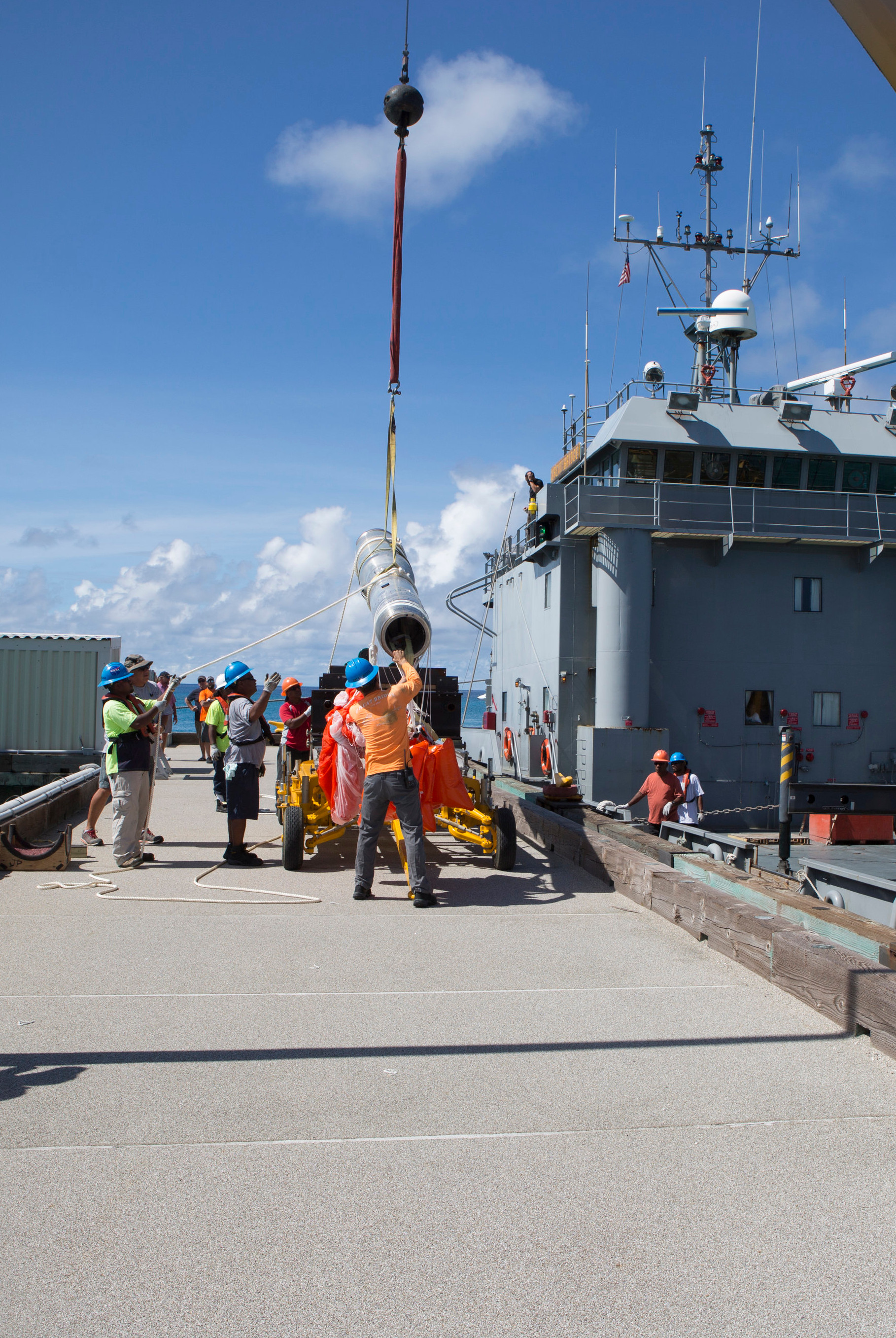
The Water Recovery X-ray Rocket was launched on April 4, 2018 from the Kwajalein Atoll in the Marshall Islands. Figure 1 shows the rocket before, during and after the launch. The total experiment time was with while pointing on target. Both telescopes survived the launch, observation and impact when the rocket landed on the water. A damage to the rocket fuselage was caused during descend by uneven heat dissipation. However, despite a breach of the electronics compartment has caused a water leakage on our hermetic electronics box, the electronics inside of the box survived and data were recovered.
Analysis of the data shown that the internal pressure in the optics compartment has temporarily spiked during the launch [17]. This was presumably caused by a water vapor outgassing. The optics and electronics section of the payload were supposed to be isolated according to the original flight plan and the optics compartment was planned to be pumped out to high vacuum. Instead, the both sections were connected due to a last-moment failure of the ion pump for the optics section. It is suspected that water from the payload skins caused a rise in the compartment pressure [17] and could later condensed and formed ice on the instrumentation.
The goal of this mission was to verify the TRL of the devices which successfully worked during the REX mission.
3.2 Inertial Measurement Unit
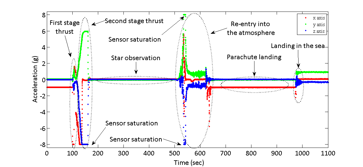
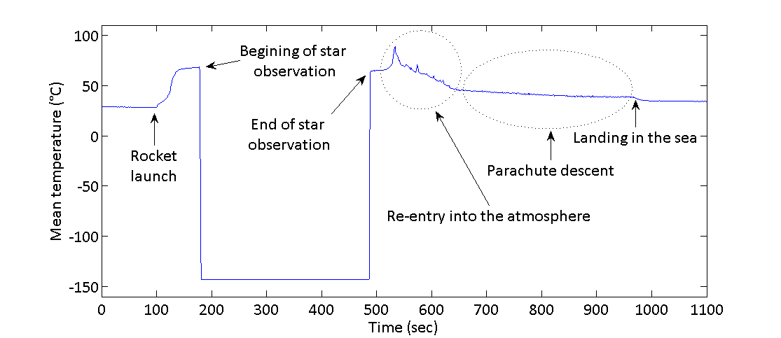
The recorded data show consistent values from the beginning of the mission until the rocket parachute landed into the ocean and stayed floating in the water. All of these facts indicate that the sensor survived the mission. The main phases of the flight are labeled in Figure 9, and it shows the thrust phase of the first and the second rocket engine stage, fast rocket detumbling before observation of stars, zero gravity observing phase, reentry into the atmosphere, parachute descending, impact onto the water surface and free floating in water. The MPU6000 sensor was partly in saturation during the full engine thrust due to its higher sensitivity setting, but it survived an acceleration of almost and an angular velocity of more than . The achieved results are promising and, therefore, the MPU6000 will be used in the future mission of PilsenCUBE II satellite.
3.3 Visible camera and payload pointing
Reliable recognition of low brightness stars in the image required long exposure time and high gain of the image sensor due to its small pixel pitch. However, these parameters also increase the dark current and thermal noise which lead to the degradation of images, especially when the image sensor has a higher temperature. Since many aspects of the suborbital mission were not known during the payload preparation, we did not have simulations of the expected camera heating. We proposed a special camera capture mode with changing exposure settings in the loop and with idle intervals between the individual batches of image frames to overcome this issue of thermal uncertainty. The capture mode started recording a batch of image frames as soon as the rocket electronics were switched on shortly before the launch. Each batch of image frames consists of several different combinations of exposure time settings (from up to ) and sensor gain settings (from up to ). The low power mode was inserted for a short time between two batches to reduce heating of the camera. Several different exposure settings minimized the risk of inappropriate camera settings due to unforeseen temperature conditions and could also be used for the combination of images during the post-processing.
Figure 11 represents a sample of original images captured during the suborbital flight, which were strongly affected by fixed pattern noise and thermal noise. Only a few of the brightest stars can be recognized, but not clearly due to strong noise artifacts in the images.
Camera temperature was almost constant near during the observation part of the mission, as shown in Figure 10. Small periodical increases and decreases of camera temperature were caused by the low power mode being switched on between batches of images to avoid overheating, but the main temperature envelope was given by the temperature of mechanical structures in the rocket and their changes during ascending, observation, descending and the landing phase of the mission.
Most of the fixed pattern noise was removed by the dark image subtraction, because it is almost constant for given exposure settings and camera temperature. Dark images were captured for all exposure settings when the rocket was in the ascending and descending phase of the mission in a closed instrumentation section. Results of dark image compensation are shown in Figure 12. Nonlinear amplification and thresholding were also applied to increase the image clarity.
Bright stars can be well recognized after removing the fixed pattern noise artifacts, however the high amount of thermal noise is still present in the images, covering and masking the weak stars. The thermal noise was additionally suppressed by applying a spatial and temporal averaging filter on the series of images captured during the attitude stabilized phase of star observation. The results of averaging eight images in series and spatial averaging with 3 3 neighboring pixels are shown in Figure 13.
Most of the thermal noise was suppressed by averaging filters and this enabled less bright stars to be recognized (apparent magnitude 8). Some residual fixed pattern and thermal noise is still present in the images, but stars can be successfully identified. A comparison of the processed image with the Stellarium star map shows a good match in Figure 14.
The small and cheap camera successfully fulfilled the task in the suborbital mission and confirmed the targeting of the X-ray telescopes. Use of these cameras in small satellites like CubeSat requires capturing a dark image and having a long exposure time (which requires attitude stabilization).
3.4 Infrared sensor array
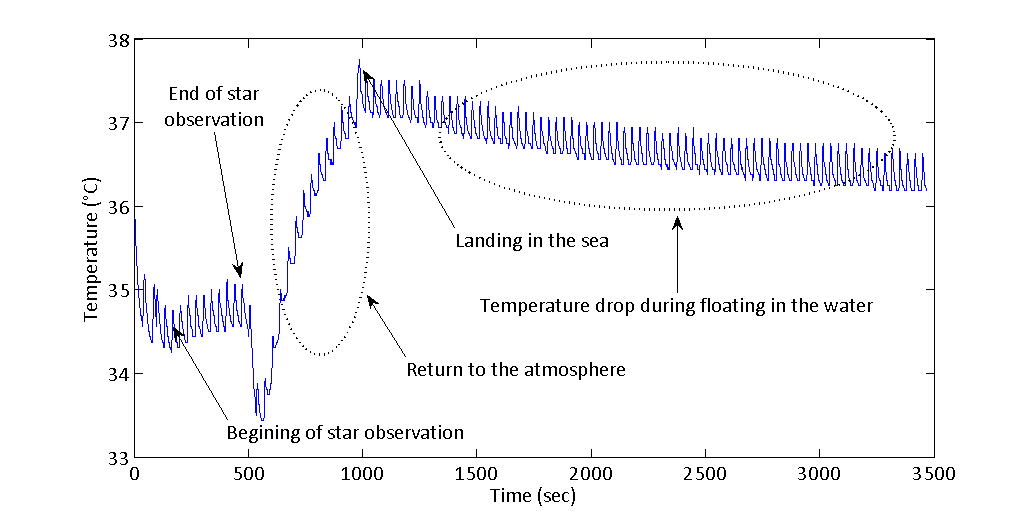
Unfortunately, the timing of the rocket stabilization and door opening and closing in the scientific section did not show the Earth to the FOV of the Grid-EYE sensor, but valuable data were nevertheless obtained. As this and similar IR arrays contain IR lenses, sensors should not have to experience high acceleration and the conditions during rocket launch are far behind the recommended operation limits. However, the thermal image had sharp edges during the observation part of the mission so it indicates that the IR lenses survived the launch conditions. During the ascending and descending phase of the mission, the sensor’s FOV was the door and the mechanical structure of the rocket. The thermal data from the sensor (Figure 15) indicated the heating of the inner rocket structure from the initial 25 – 30 up to , due to friction of the atmosphere during the ascending phase, followed by a fast decrease of temperature down to (post-processed value), after the door opening for the phase of star observation. Closing the science section door and reentry into the atmosphere caused a short increase of temperature of the inner mechanical structure, followed by cooling during its slow parachute descent and landing into the ocean.
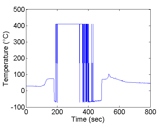
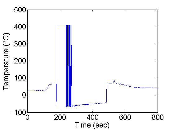
The most interesting data were expected after opening the science section and subsequent exposure of the sensor to the absence of heat from space, and to the heat of the rocket structure, both concurrently in the FOV of the sensor, where the sensor is exposed to a high dynamic range of measured temperatures. However, the sensor suffered from a software overflow or sensitivity switching in this situation and the sensor’s pixels shift numeric representation of temperatures approximately one half of the numeric range, which leads to a false interpretation of the measured temperatures from two complement binary representation. This can be seen in Figure 16, where the readout temperature of the pixels alternates between high temperature and low temperature.
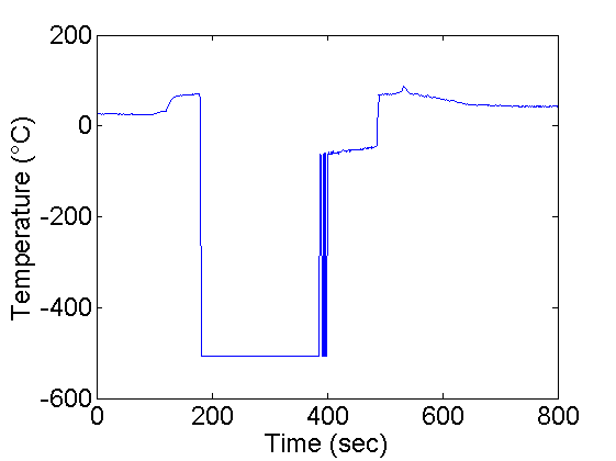
The overflow behavior was compensated in post-processing based on the numeric range of the temperature oscillations and knowing the expected temperature values for specific locations of the rocket structure in the sensor FOV. Compensated temperatures with the opened scientific section are shown in Figure 17 as the mean value of four pixels in the middle of the AMG88 Grid-EYE sensor.
The tested IR array sensor AMG88 is usable for simple and non-critical application in similar missions, even with the instability of numeric representation of temperatures. The temperature changes in the FOV are detectable, only the absolute value of temperature is unreliable. The sensor can be used, for example, as a simple detector for the release of the deployable parts, covering the sensor in the stowed state and opening the sensor FOV to space in the deployed state. Using this sensor as an Earth horizon detector in the ADCS of small satellites is not suitable with this particular sensor due to its instability of numeric representation of temperatures.
3.5 X-ray telescopes
Both X-ray detectors were autonomously operated by a custom-built software [22] in ROS. Data from both detectors were acquired using as a continuous stream of acquisitions that started before launch.
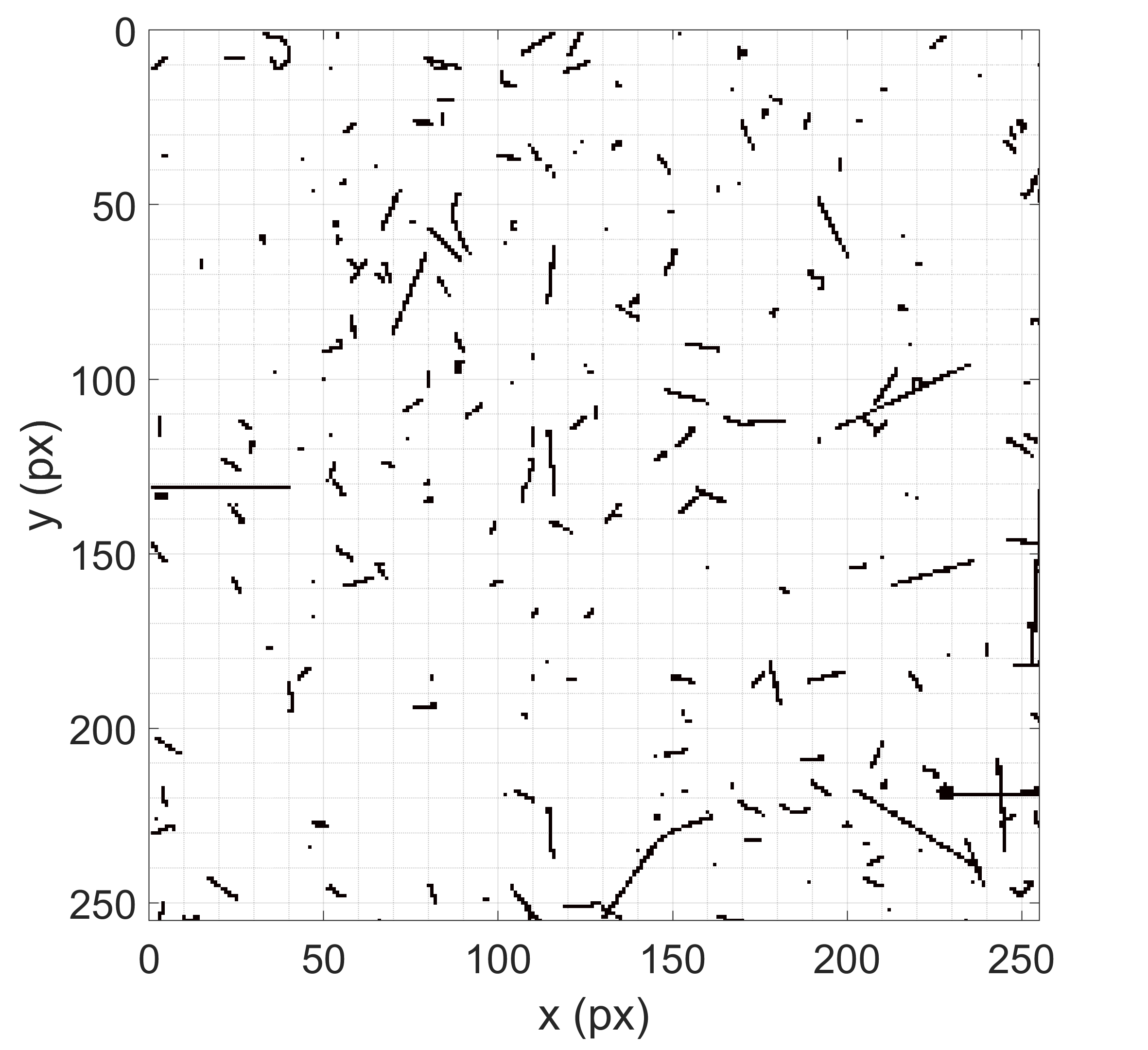
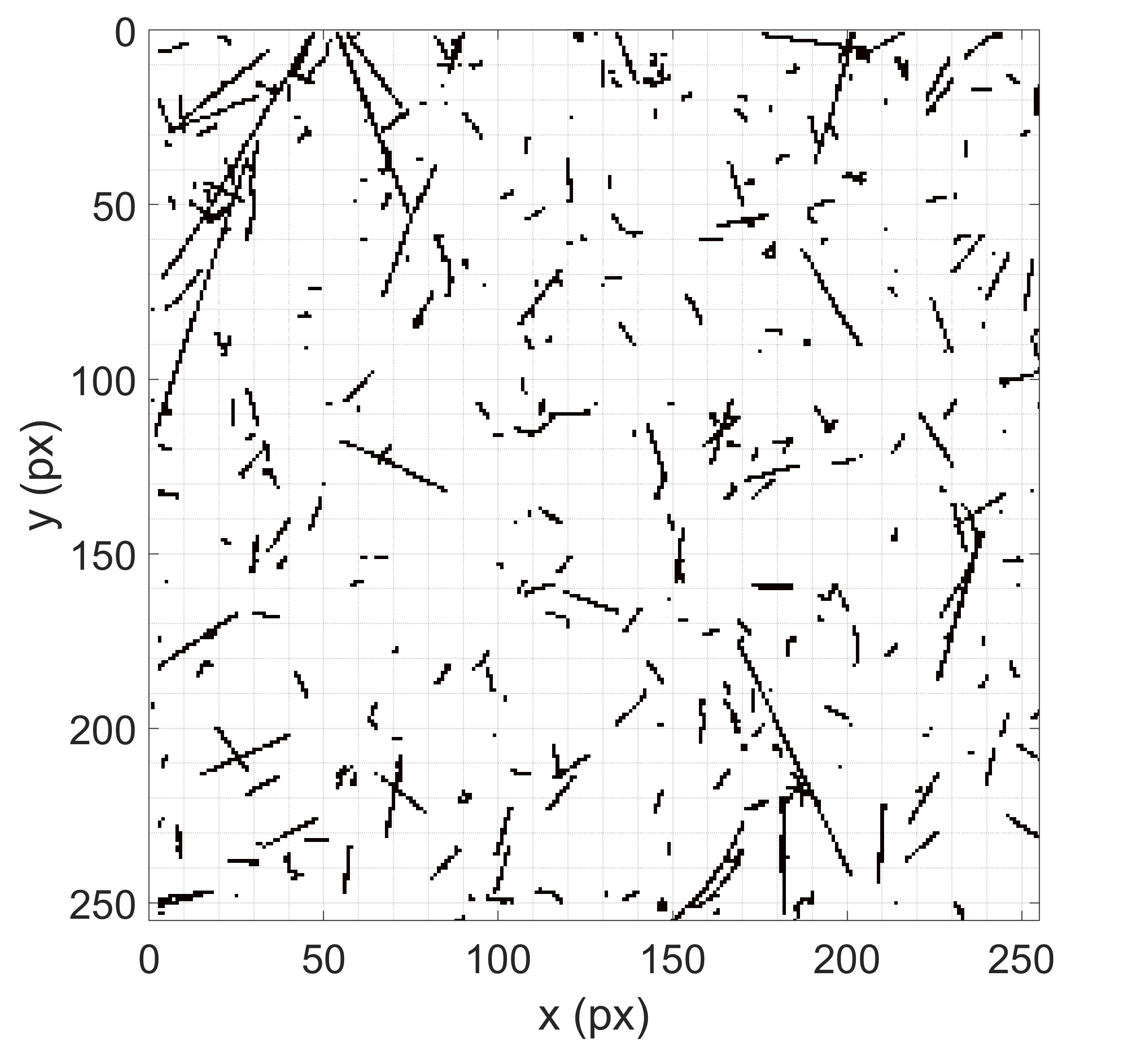
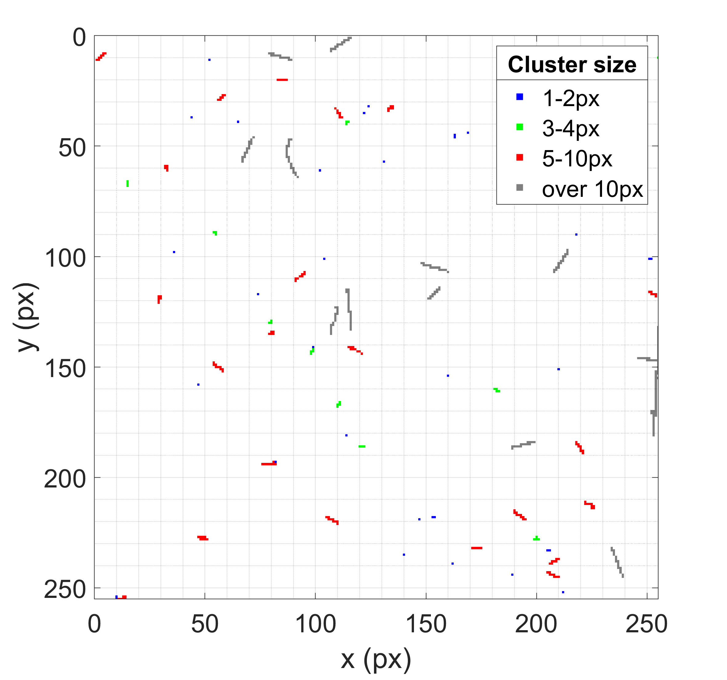
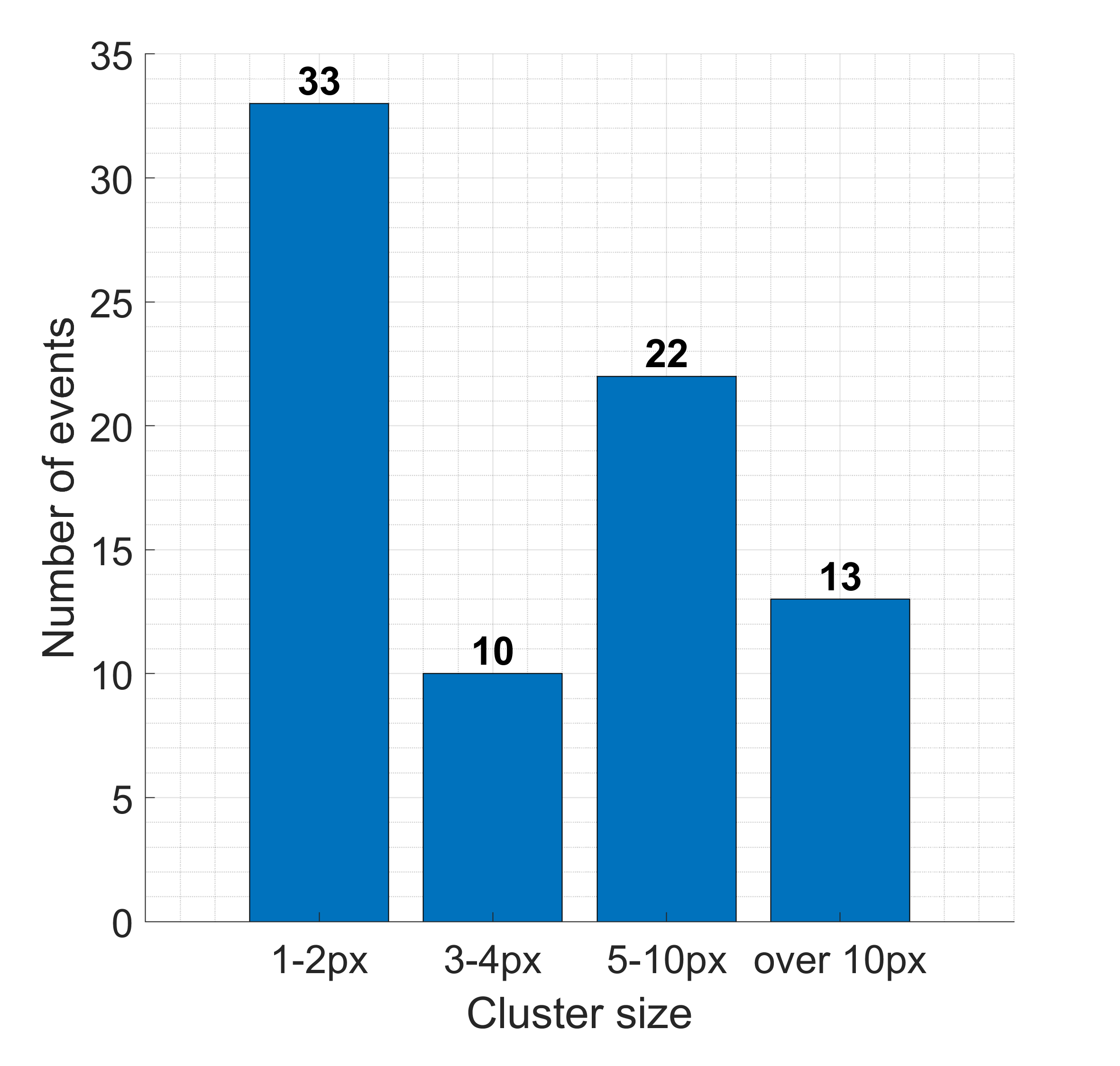
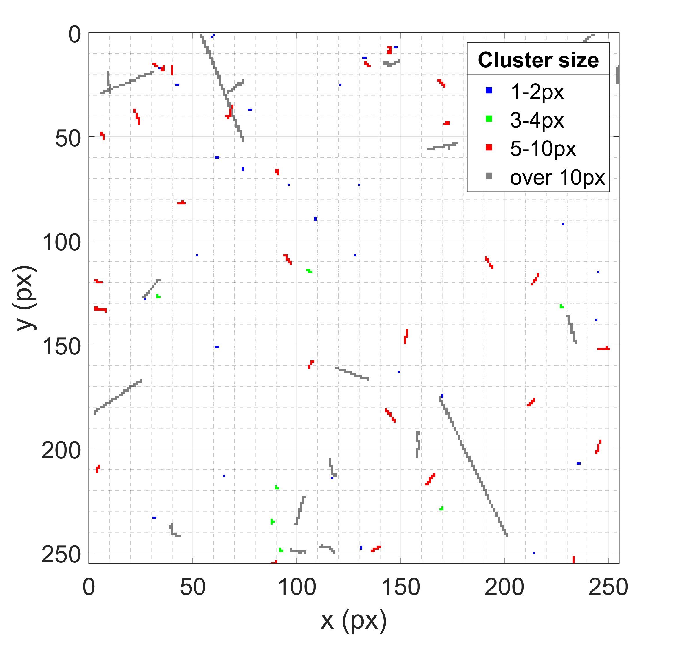
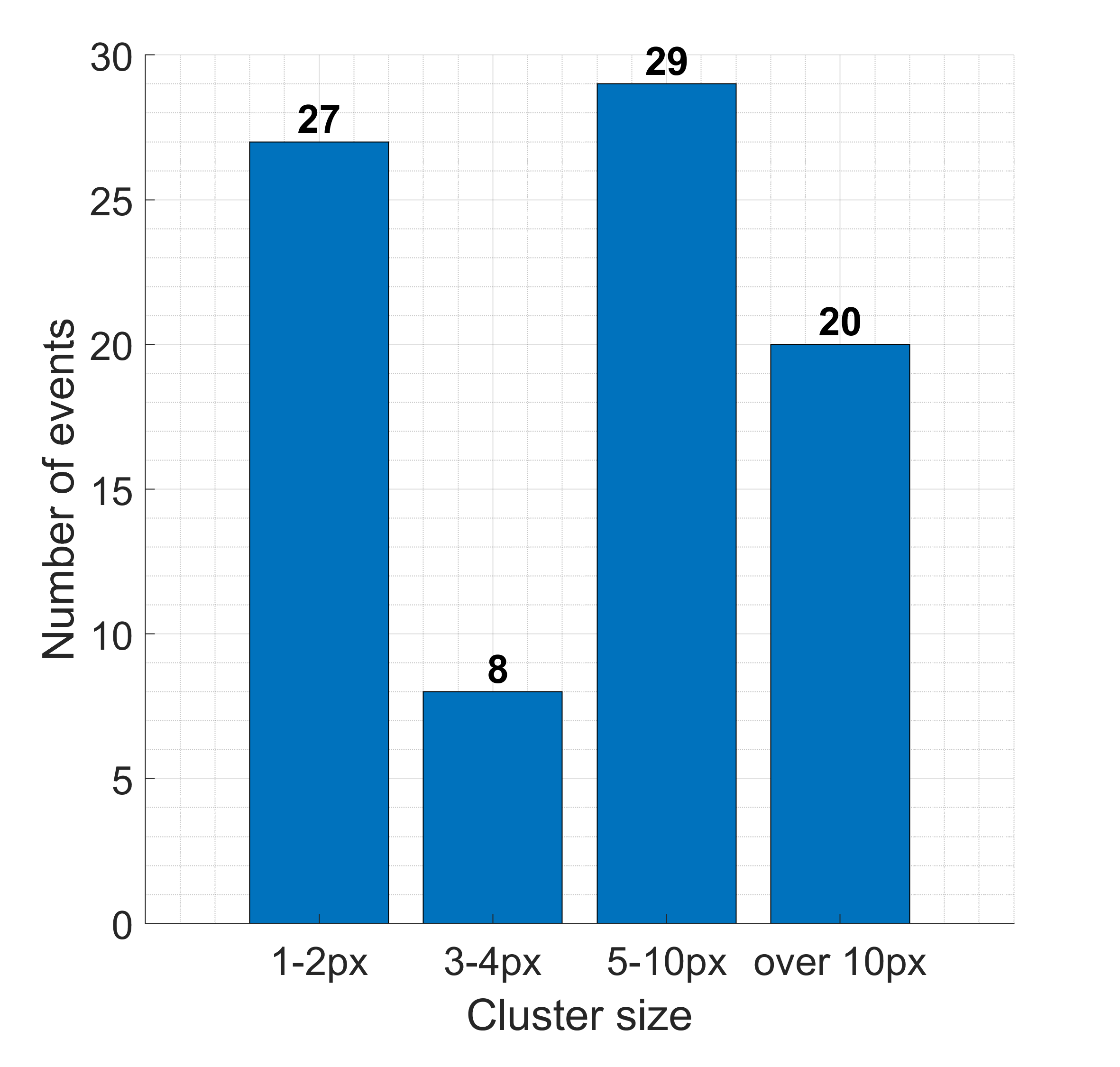
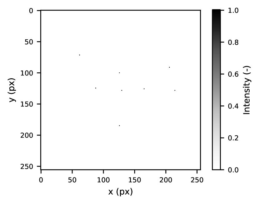
Both X-ray telescopes (1D and 2D) took images during the entire duration of the rocket’s flight (Figure 18). Figures 19(a), and 20(a) represent filtered integral images from both telescopes while the rocket pointing at the Vela pulsar. Thanks to the data sensing system, it was possible to recognize and filter out individual events based on the size of their tracks or their dissipated energy in the detection layer. The results of track size classification are shown in color. The main areas of interest were gamma particles (photons with a range of energies between to ), which in the case of the Si detector, leave mostly single-pixel events on the detector [39]. However, photons can strike multiple pixels due to charge-sharing among the neighboring pixels. During the evaluation of the measurement, we considered 1 – 4 events as gamma photons.
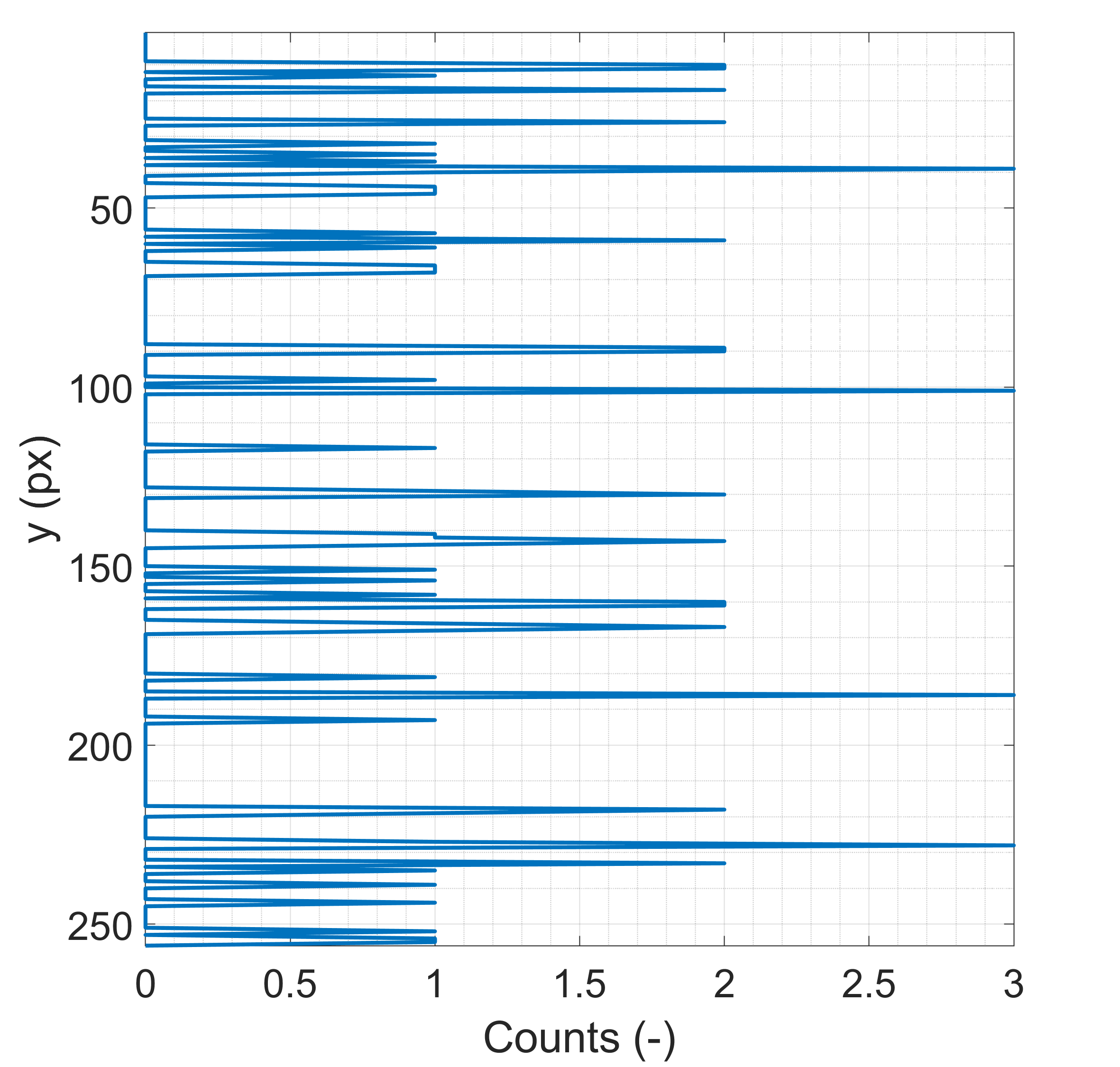
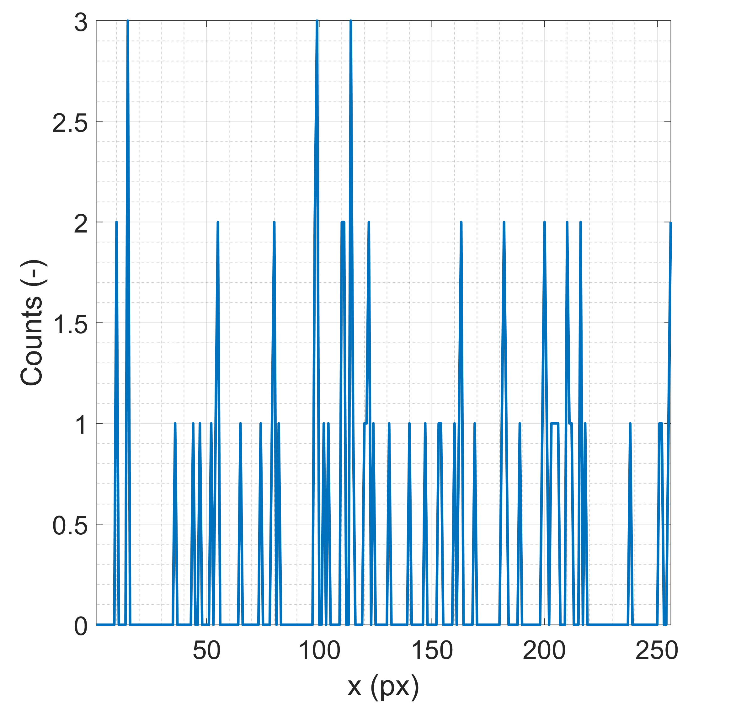
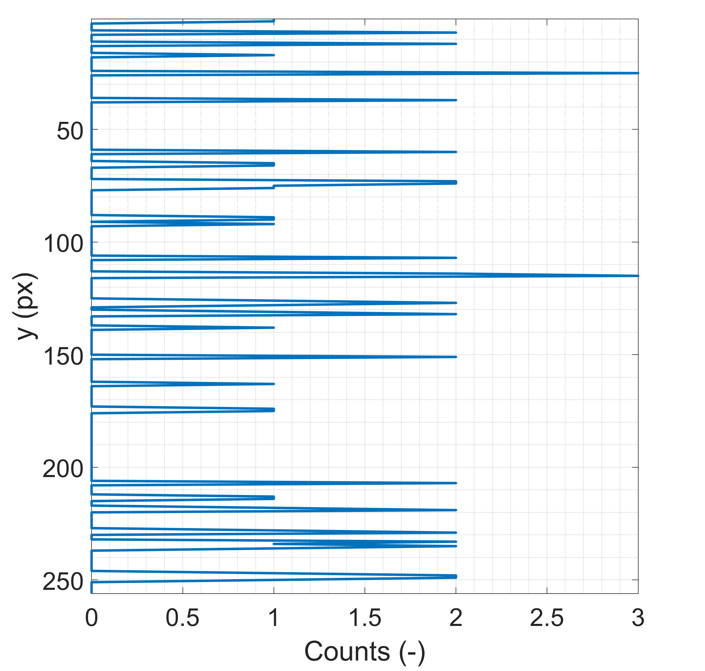
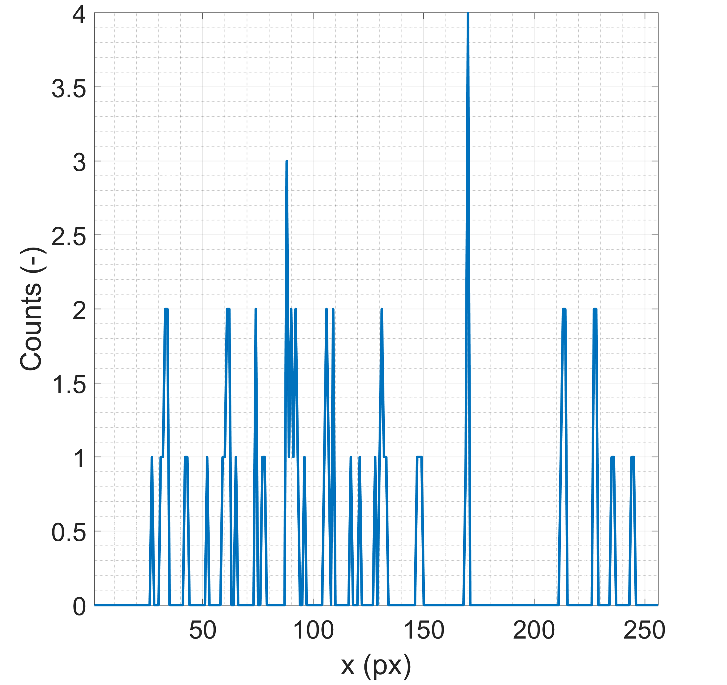
The filtered images, formed only by impacts of gamma particles, were evaluated as horizontal and vertical projections. Sums of individual rows and columns were plotted as a line graphs, which effectively produces integral images of 256 line-detectors. This technique makes it easier to detect the position the focus line (1D) and cross (2D), since the focus is always aligned with the detector rows and columns. Figure 19 shows the processed and filter data from the 1D telescope, Figure 20 depicts the data from the 2D telescope.
As it can be seen in the images, a small number of particles was collected on both detectors. Despite the approx. 43 (1D) respectively 35 (2D) X-ray gamma events taken during the observation time, no apparent focal point/line or preferential event positions was observed. The total supposed X-ray counts during the whole observation were 5 photons for the 1D optics and 27 photons for the 2D optics. The results show no statistical tendency to form a focus line by the 1D telescope or focus point by the 2D telescope. In fact, majority of the measured signal originates from ambient background radiation, which was recorded equally by both detectors.
Another reasons for such a small photon count yield might be a water condensation on the optics surfaces, as suggested by [17]. Water vapor condensing on the surfaces of the LE optics foils would diminish the intensity, especially for soft X-rays. However, the real reason is unclear as not enough data supports this hypothesis for the REX payload. Importantly for the TRL evaluation, both the optics and the electronics have survived the experiment and all the subsystems were fully operational.
4 Conclusion
The Rocket Experiment was one of two payloads on the suborbital rocket campaign launched from the Marshall Islands on April 4, 2018. The mission goal was to demonstrate the space performance of X-ray multifoil telescopes in combination with an uncooled pixel detector Timepix and the verification of the Technology Readiness Level. The payload contained a number of other sensors and devices, for observation in the visible, infrared, and X-ray spectra. The payload system was operated by the custom-made automatic software Rospix, developed specifically for this experiment. Due to the low intensity of the source, the measurements did not yield sufficient results for X-ray observations of the Vela Supernova Remnant, however, we can report that all instruments in the proposed system worked successfully and without problems during the experiment. Based on the obtained results, the functionality and the possibility of using the proposed system for similar upcoming experiments was confirmed.
Acknowledgements
The team of authors of this article would like to thank the whole team of colleagues who participated in this project, not only: Ondřej Petr (Rigaku Innovative Technologies s.r.o.), Robert Filgas (Czech Technical University in Prague), Richard Linhart (University of West Bohemia) and Pavel Fiala (University of West Bohemia) and many others without which this project did not arise.
This project was performed in collaboration with several universities, companies and scientific institutions in the Czech Republic and abroad. Namely: Czech Technical University in Prague (CZE) - Institute of Experimental and Applied Physics and Faculty of Electrical Engineering, University of West Bohemia (CZE), Rigaku Innovative Technologies s.r.o. (CZE), Czech Aerospace Research Centre a.s. (CZE), PANTER facility of the Max Planck Institute for Extraterrestrial Physics (DEU), Pennsylvania State University (USA), University of Colorado at Boulder (USA).
Many thanks for the willingness, help and pieces of advice belonging to namely: D. Burrows with his team (PSU), W. Cash with teams (CU Boulder), V. Burwitz with the team (PANTER).
The project was supported by the Technology Agency of the Czech Republic under grants no: TA03011329, TA04011295, the Grant Agency of the Czech Republic under grant no. 18-10088Y, the NASA Astrophysics Research and Analysis grant NNX17AC88G, the Grant Agency of the Czech Technical University in Prague no. SGS18/186/OHK3/3T/13, and by the Ministry of Education and Youth of the Czech Republic, project no. LTAUSA18094. This work was done on behalf of Medipix2 collaboration.
References
- Christe et al. [2016] S. Christe, B. Zeiger, R. Pfaff, M. Garcia, Introduction to the Special Issue on Sounding Rockets and Instrumentation, Journal of Astronomical Instrumentation 05 (2016) 1602001. doi:10.1142/S2251171716020013.
- Robertson et al. [2014] S. Robertson, S. Dickson, M. Horányi, Z. Sternovsky, M. Friedrich, D. Janches, L. Megner, B. Williams, Detection of meteoric smoke particles in the mesosphere by a rocket-borne mass spectrometer, Journal of Atmospheric and Solar-Terrestrial Physics 118 (2014) 161–179. doi:10.1016/j.jastp.2013.07.007.
- Moses et al. [2020] J. D. Moses, E. Antonucci, J. Newmark, F. Auchère, S. Fineschi, M. Romoli, D. Telloni, G. Massone, L. Zangrilli, M. Focardi, F. Landini, M. Pancrazzi, G. Rossi, A. M. Malvezzi, D. Wang, J.-C. Leclec’h, J.-P. Moalic, F. Rouesnel, L. Abbo, A. Canou, N. Barbey, C. Guennou, J. M. Laming, J. Lemen, J.-P. Wuelser, J. L. Kohl, L. D. Gardner, Global helium abundance measurements in the solar corona, Nature Astronomy (2020). doi:10.1038/s41550-020-1156-6.
- Dirienzo and Kisiolek [2017] W. Dirienzo, R. Kisiolek, RockOn Workshop, Proceedings of the Wisconsin Space Conference 1 (2017). doi:10.17307/wsc.v1i1.188.
- Council [2010] N. R. Council, Revitalizing NASA’s Suborbital Program, National Academies Press, Washington, D.C., 2010. doi:10.17226/12862.
- Cha et al. [1999] A. N. Cha, K. R. Sembach, A. C. Danks, The Distance to the Vela Supernova Remnant, The Astrophysical Journal 515 (1999) L25–L28. doi:10.1086/311968.
- Daniel et al. [2019] V. Daniel, A. Inneman, I. Vertat, T. Baca, O. Nentvich, M. Urban, V. Stehlikova, L. Sieger, P. Skala, R. Filgas, V. Zadrazil, R. Linhart, J. Masopust, T. Jamroz, L. Pina, V. Marsikova, L. Mikulickova, E. Belas, S. Pospisil, Z. Vykydal, Y. Mora, R. Pavlica, In-Orbit Commissioning of Czech Nanosatellite VZLUSAT-1 for the QB50 Mission with a Demonstrator of a Miniaturised Lobster-Eye X-Ray Telescope and Radiation Shielding Composite Materials, Space Science Reviews 215 (2019) 40. doi:10.1007/s11214-019-0589-7.
- Miles et al. [2017] D. M. Miles, R. L. McEntaffer, T. B. Schultz, B. D. Donovan, J. H. Tutt, D. Yastishock, T. Steiner, C. R. Hillman, J. A. McCoy, M. Wages, S. Hull, A. Falcone, D. N. Burrows, T. Anderson, M. McQuaide, T. Chattopadhyay, An introduction to the water recovery x-ray rocket, in: O. H. Siegmund (Ed.), UV, X-Ray, and Gamma-Ray Space Instrumentation for Astronomy XX, SPIE, 2017, p. 28. doi:10.1117/12.2274249.
- Seward and Charles [2010] F. D. Seward, P. A. Charles, Exploring the X-ray Universe, Cambridge University Press, Cambridge, 2010. doi:10.1017/CBO9780511781513.
- Gorenstein et al. [1974] P. Gorenstein, J. Harnden, F. R., W. H. Tucker, The X-ray spectra of the VELA and Puppis supernova remnants and the shock-wave model of supernova remnants, The Astrophysical Journal 192 (1974) 661. doi:10.1086/153103.
- Burkert et al. [1982] W. Burkert, H. Zimmermann, B. Aschenbach, H. Braeuninger, F. Williamson, Soft X-ray filter spectroscopy of the supernova remnants VELA X and Puppis A, Astronomy and Astrophysics (1982).
- Kahn et al. [1985] S. M. Kahn, P. Gorenstein, J. Harnden, F. R., F. D. Seward, Einstein observations of the VELA supernova remnant - The spatial structure of the hot emitting gas, The Astrophysical Journal 299 (1985) 821. doi:10.1086/163748.
- Bamba et al. [2005] A. Bamba, R. Yamazaki, J. S. Hiraga, Chandra Observations of Galactic Supernova Remnant Vela Jr.: A New Sample of Thin Filaments Emitting Synchrotron X‐Rays , The Astrophysical Journal (2005). doi:10.1086/432711.
- Llopart et al. [2007] X. Llopart, R. Ballabriga, M. Campbell, L. Tlustos, W. Wong, Timepix, a 65k programmable pixel readout chip for arrival time, energy and/or photon counting measurements, Nuclear Instruments and Methods in Physics Research Section A: Accelerators, Spectrometers, Detectors and Associated Equipment 581 (2007) 485–494. doi:10.1016/j.nima.2007.08.079.
- Miles et al. [2019] D. M. Miles, S. V. Hull, T. B. Schultz, J. H. Tutt, M. Wages, B. D. Donovan, R. L. McEntaffer, A. D. Falcone, T. Anderson, E. Bray, D. N. Burrows, T. Chattopadhyay, C. M. Eichfeld, N. Empson, F. Grisé, C. R. Hillman, J. A. McCoy, M. McQuaide, B. J. Myers, T. Steiner, M. A. Verschuuren, D. Yastishock, N. Zhang, Water Recovery X-Ray Rocket grating spectrometer, Journal of Astronomical Telescopes, Instruments, and Systems 5 (2019) 1. doi:10.1117/1.JATIS.5.4.044006.
- Tutt et al. [2019] J. H. Tutt, R. L. McEntaffer, D. M. Miles, B. D. Donovan, C. Hillman, Grating Alignment for the Water Recovery X-Ray Rocket (WRXR), Journal of Astronomical Instrumentation 08 (2019) 1950009. doi:10.1142/S2251171719500090.
- Wages et al. [2019] M. Wages, S. V. Hull, A. D. Falcone, T. B. Anderson, M. McQuaide, E. Bray, T. Chattopadhyay, D. N. Burrows, L. Buntic, R. M. McEntaffer, D. M. Miles, J. H. Tutt, T. B. Schultz, B. D. Donovan, C. R. Hillman, D. Yastishock, Flight camera package design, calibration, and performance for the Water Recovery X-ray Rocket mission, in: O. H. Siegmund (Ed.), UV, X-Ray, and Gamma-Ray Space Instrumentation for Astronomy XXI, SPIE, 2019, p. 12. doi:10.1117/12.2529361.
- Schmidt [1975] W. Schmidt, A proposed X-ray focusing device with wide field of view for use in X-ray astronomy, Nuclear Instruments and Methods 127 (1975) 285–292. doi:10.1016/0029-554X(75)90501-7.
- Angel [1979] J. R. P. Angel, Lobster eyes as X-ray telescopes, The Astrophysical Journal 233 (1979) 364. doi:10.1086/157397.
- Hudec [2010] R. Hudec, Kirkpatrick-Baez (KB) and lobster eye (LE) optics for astronomical and laboratory applications, X-Ray Optics and Instrumentation 2010 (2010) 1–39. doi:10.1155/2010/139148.
- Pina et al. [2018] L. Pina, R. Hudec, A. Inneman, O. Nentvich, M. Urban, V. Marsikova, V. Stehlíková, D. Doubravova, V. Burwitz, C. Pelliciari, G. Hartner, V. Daniel, Multi-Foil X-ray optics tests at PANTER: Preliminary results, Contributions of the Astronomical Observatory Skalnate Pleso 48 (2018) 466–475.
- Baca et al. [2018] T. Baca, D. Turecek, R. McEntaffer, R. Filgas, Rospix: modular software tool for automated data acquisitions of Timepix detectors on Robot Operating System, Journal of Instrumentation 13 (2018) C11008–C11008. doi:10.1088/1748-0221/13/11/C11008.
- Urban et al. [2017] M. Urban, O. Nentvich, V. Stehlikova, T. Baca, V. Daniel, R. Hudec, VZLUSAT-1: Nanosatellite with miniature lobster eye X-ray telescope and qualification of the radiation shielding composite for space application, Acta Astronautica 140 (2017) 96–104. doi:10.1016/j.actaastro.2017.08.004.
- Willmore et al. [1992] A. P. Willmore, C. J. Eyles, G. K. Skinner, M. P. Watt, Hard X-ray emission from the Vela supernova remnant, Monthly Notices of the Royal Astronomical Society 254 (1992) 139–145. doi:10.1093/mnras/254.1.139.
- Nentvich et al. [2019] O. Nentvich, M. Urban, M. Blažek, A. Inneman, R. Hudec, L. Sieger, Lobster eye optics: position determination based on 1D optics with simple code mask, in: C. Morawe, A. M. Khounsary, S. Goto (Eds.), Advances in X-Ray/EUV Optics and Components XIV, SPIE, 2019, p. 31. doi:10.1117/12.2528505.
- Vykydal and Jakubek [2011] Z. Vykydal, J. Jakubek, USB Lite – Miniaturized readout interface for Medipix2 detector, Nuclear Instruments and Methods 633 (2011) S48–S49.
- Kraus et al. [2011] V. Kraus, M. Holik, J. Jakubek, M. Kroupa, P. Soukup, Z. Vykydal, FITPix—fast interface for Timepix pixel detectors, Journal of Instrumentation 6 (2011) C01079.
- Granja et al. [2018] C. Granja, K. Kudela, J. Jakubek, P. Krist, D. Chvatil, J. Stursa, S. Polansky, Directional detection of charged particles and cosmic rays with the miniaturized radiation camera MiniPIX Timepix, Nuclear Instruments and Methods in Physics Research Section A: Accelerators, Spectrometers, Detectors and Associated Equipment 911 (2018) 142–152.
- Trojanova et al. [2018] E. Trojanova, J. Jakubek, D. Turecek, V. Sykora, P. Francova, V. Kolarova, L. Sefc, Evaluation of Timepix3 based CdTe photon counting detector for fully spectroscopic small animal SPECT imaging, Journal of Instrumentation 13 (2018) C01001.
- Filgas [2018] R. Filgas, Space radiation monitoring with Timepix, Astronomische Nachrichten 339 (2018) 386–390. doi:10.1002/asna.201813511.
- Stoffle et al. [2015] N. Stoffle, L. Pinsky, M. Kroupa, S. Hoang, J. Idarraga, C. Amberboy, R. Rios, J. Hauss, J. Keller, A. Bahadori, E. Semones, D. Turecek, J. Jakubek, Z. Vykydal, S. Pospisil, Timepix-based radiation environment monitor measurements aboard the International Space Station, Nuclear Instruments and Methods in Physics Research, Section A: Accelerators, Spectrometers, Detectors and Associated Equipment (2015). doi:10.1016/j.nima.2015.02.016.
- Turecek et al. [2011] D. Turecek, L. Pinsky, J. Jakubek, Z. Vykydal, N. Stoffle, S. Pospisil, Small Dosimeter based on Timepix device for International Space Station, Journal of Instrumentation 6 (2011) C12037–C12037. doi:10.1088/1748-0221/6/12/C12037.
- Granja et al. [2016] C. Granja, S. Polansky, Z. Vykydal, S. Pospisil, A. Owens, Z. Kozacek, K. Mellab, M. Simcak, The SATRAM Timepix spacecraft payload in open space on board the Proba-V satellite for wide range radiation monitoring in LEO orbit, Planetary and Space Science 125 (2016) 114–129. doi:10.1016/j.pss.2016.03.009.
- Baca et al. [2016] T. Baca, M. Platkevic, J. Jakubek, A. Inneman, V. Stehlikova, M. Urban, O. Nentvich, M. Blazek, R. McEntaffer, V. Daniel, Miniaturized X-ray telescope for VZLUSAT-1 nanosatellite with Timepix detector, Journal of Instrumentation 11 (2016) C10007–C10007. doi:10.1088/1748-0221/11/10/C10007.
- Dániel et al. [2017] V. Dániel, A. Inneman, L. Pína, V. Zadražil, T. Báča, V. Stehlíková, O. Nentvich, M. Urban, V. Maršíková, R. McEntaffer, J. Tutt, T. Schulz, X-ray Lobster Eye all-sky monitor for rocket experiment, in: EUV and X-ray Optics: Synergy between Laboratory and Space V, 2017, p. 1023503. doi:10.1117/12.2277515.
- Furnell et al. [2019] W. Furnell, A. Shenoy, E. Fox, P. Hatfield, First results from the LUCID-Timepix spacecraft payload onboard the TechDemoSat-1 satellite in Low Earth Orbit, Advances in Space Research 63 (2019) 1523–1540. doi:10.1016/j.asr.2018.10.045.
- Hatfield et al. [2018] P. Hatfield, W. Furnell, A. Shenoy, E. Fox, R. Parker, L. Thomas, The LUCID-Timepix spacecraft payload and the CERN@school educational programme, Journal of Instrumentation 13 (2018) C10004–C10004. doi:10.1088/1748-0221/13/10/C10004.
- Filgas et al. [2019] R. Filgas, M. Malich, T. Kuwahara, J. Broulím, M. Holík, M. Sakal, Y. Murata, H. Tomio, S. Gohl, J. M. Pineda T., RISEPix—A Timepix‐based radiation monitor telescope onboard the RISESAT satellite, Astronomische Nachrichten 340 (2019) 674–680. doi:10.1002/asna.201913674.
- Jakubek [2011] J. Jakubek, Precise energy calibration of pixel detector working in time-over-threshold mode, Nuclear Instruments and Methods in Physics Research Section A: Accelerators, Spectrometers, Detectors and Associated Equipment 633 (2011) S262–S266. doi:10.1016/j.nima.2010.06.183.