Synthetically Encapsulated & Self-Organized Transition Metal Oxide Nano Structures inside Carbon Nanotubes as Robust Li-ion Battery Anode Materials
Abstract
We report a comprehensive study on the electrochemical performance of four different Transition Metal Oxides encapsulated inside carbon nanotubes (CNT). Irrespective of the type of oxide-encapsulate, all these samples exhibit superior cyclic stability as compared to the bare-oxide. Innovative use of camphor during sample synthesis enables precise control over the morphology of these self-organized carbon nanotube structures, which in turn appears to play a crucial role in the magnitude of the specific capacity. A comparative evaluation of the electrochemical data on different samples bring forward interesting inferences pertaining to the morphology, filling fraction of the oxide-encapsulate, and the presence of oxide nano-particles adhering outside the filled CNT. Our results provides useful pointers towards the optimization of critical parameters, thus paving the way for using these synthetically encapsulated and self-organized carbon nanotube structures as anode materials for Li-ion batteries, and possibly other electrochemical applications.
pacs:
Valid PACS appear hereI Introduction
Li-ion batteries (LIBs) are a critical component of most advanced technologies of the modern era, and represent perhaps the most sought after energy storage devices of these times.Goodenough and Park (2013); Peters et al. (2017); Hameer and van Niekerk (2015); Aravindan et al. (2015) The commercial LIBs employ graphite as the anode material which has a theoretical capacity of 372 mA h g-1.Ji et al. (2011) Transition metal oxides (TMOs) have attracted considerable attention as promising anode materials due to their higher theoretical capacities in comparison to graphite. Additional advantages of these TMOs include low cost, abundant resources, and low toxicity. Though the experimentally observed capacities are lower, these can be substantially improved via nano scaling. Therefore, TMOs have been extensively explored in their nano-flower, nano-flake, and nano-porous morphologies.Zhang and A.Yu (2015); Zheng et al. (2018); Tian et al. (2018); Cao et al. (2017); Zhang et al. (2011); Fan et al. (2017); Liu and Wang (2014); Reddy et al. (2007); Li et al. (2016); Pang et al. (2016) The lithium storage capacity of TMOs is ascribed to the reversible reaction between Li ions and metal oxide(s) which leads to the formation of metal nanoparticles in a Li2O matrix. Superior capacity of TMOs can also be attributed to its storage mechanism, in which the number of Li ions available for intercalation is more compared to the classical intercalation, limited to 1 Li+/f.u.Zhang and A.Yu (2015); Zheng et al. (2018); Tian et al. (2018); Cao et al. (2017); Zhang et al. (2011); Fan et al. (2017); Liu and Wang (2014); Reddy et al. (2007); Li et al. (2016); Pang et al. (2016) However, the practical applications using TMOs as an active material are primarily hampered due to the large volume expansion and contraction during the metal to metal-oxide conversion. This conversion leads to a rupture of the separator and destruction of the electrode during the electrochemical reaction.Ji et al. (2011) This issue of capacity fading which adversely affects the cyclic stability, along with the intrinsic low electrical conductivity are major detrimental factors for TMOs based LIBs.
An effective strategy to improve the structural stability and the electrical conductivity is the use of hybrids based on carbonaceous materials and TMOs in the electrode design.Peters et al. (2017); Song and Ma (2018); Ji et al. (2011); Wang et al. (2018); Wua et al. (2012); Zhao et al. (2017); Jiang et al. (2017); Yang et al. (2011); Wang et al. (2017); Xu et al. (2018) In this context, CNT/ TMOs hybrids have been explored, as CNT possess excellent electrical conductivity and mechanical stabilityYan et al. (2013); Zhou et al. (2016); Zhang et al. (2010); Cao and Wei (2015); Ottmann et al. (2017); Puthusseri et al. (2016); Tang et al. (2019); Liu et al. (2017a); Ottmann et al. (2020); E.Thauer et al. (2020); Choi et al. (2015). The exceptional mechanical strength of CNT can also be utilized to buffer the volumetric strain in the electrode materials during charging/discharging processesYan et al. (2013); Zhou et al. (2016); Zhang et al. (2010); Cao and Wei (2015); Ottmann et al. (2017); Puthusseri et al. (2016); Tang et al. (2019); Liu et al. (2017a); Xu et al. (2018); Choi et al. (2015); Ottmann et al. (2020); E.Thauer et al. (2020). Here it is important to distinguish two distinct scenarios pertaining to the usage of oxide-CNT hybrids for LIB. In the first, the CNT and the oxide are synthesized separately and processed to form the composite Bahadur et al. (2018); Xu et al. (2018); Song and Ma (2018); Wang et al. (2017); Yang et al. (2011); Cao and Wei (2015); Choi et al. (2015); Wang et al. (2016); Cao et al. (2016). Alternatively, the oxide is synthetically encapsulated within the core cavity of the CNT in the form of nano particles or nano wires Yan et al. (2013); Ottmann et al. (2017); Puthusseri et al. (2016); Liu et al. (2017a). The core cavity of the CNT in this case can provide space for the volume-changes that take place during metal to metal-oxide conversion. In this work, we present extensive electrochemical data on self-organized CNT structures, pertaining to the second case, with the TMOs being synthetically encapsulated within the core cavity of the CNT (Oxides@CNT). We reiterate that while FeOx@CNT has been tested as an anode material,Wang et al. (2016); Liu et al. (2017a); Yan et al. (2013); Cheng et al. (2013); Liu et al. (2017b) to the best of our knowledge, CoOx & NiOx@CNT with significant filling efficiencies (such as presented in this work) have not yet been explored for LIBs, primarily due to difficulties related to the synthesis of such systems Kapoor et al. (2018).
In addition to the morphology of the active material, other important factors that are likely to influence the overall battery performance for Oxides@CNT are (i) type of the oxide encapsulate and its size and shape, (ii) filling efficiencies, and (iii) the role played by oxide nano-particles (NP) adhering outside the CNT.Ji et al. (2011); Ottmann et al. (2020) In addition to such residual NP, there can be big chunks of oxide clusters, which at times form during the synthesis. Here we present comparative electrochemical data on four different types of TMOs encapsulated inside CNT. Our key result is that the encapsulation of TMOs within the core cavity of CNT leads to a significant improvement in the cyclic stability of the electrode, irrespective of its type. The paper is organized as follows. We first present complete structural and electrochemical characterization, bringing out the correlations between the two. For this, Fe3O4@CNT, Co3O4@CNT and NiO@CNT are investigated. The effect of morphology is further explored with focus on Fe2O3@CNT. These data reveal how the over-all morphology as well as oxide NP residing outside filled CNTs affect the cyclic stability. Morphology variations in Fe2O3@CNT also establish that Oxides@CNT formed in entangled morphology is preferable for the cyclic stability and may play a role in improving the magnitude of capacity. Finally, we compare the cyclic stability of different Oxides@CNT with that of a representative bare-oxide. Here the bare-oxide has been derived from the corresponding Oxide@CNT, and hence retains the same morphology. This comparison enables us to isolate the advantages associated with the encapsulation of TMOs inside CNT.
II Experimental Section
II.1 Oxides@CNT : Synthesis and Characterization
The furnace employed for synthesis of the oxides filled CNT was Nabertherm R 100/750/13.The Scanning Electron Microscopy (FESEM) images were recorded using ZEISS ULTRA plus field-emission FESEM for morphological studies. All the samples have been characterized using X-ray powder diffraction (XRD) using Bruker D8 Advance with Cu-K radiation ( = 1.54056Å). The thermal analysis was determined by a thermogravimetric analyser, Perkin Elmer STA 6000, under air at 20 mL min-1 at a heating rate of 15oC min-1 from 30oC to 900oC. Raman spectroscopy measurements were performed on HORIBA JOBIN YVON LabRam HR 800 with an excitation wavelength of 488nm.
The high quality samples of oxides@CNT are synthesized by using a two step process. The first step involves preparation of metal@CNT (Fe@CNT, Co@CNT and Ni@CNT) by using pyrolysis of metallocene.Kapoor et al. (2018) A few representative TEM images of all three metal@CNT are shown in Supp. Information: Figure S1(a-c) for Fe@CNT, S2(a-c) for Ni@CNT, and S3(a-c) for Co@CNT. In the second step, the metal@CNT are converted to their respective Oxide@CNT using a suitable annealing protocol Kapoor et al. (2018). Broad area FESEM images, depicting overall morphology of various Oxides@CNT are shown in Supp. Information: Figure S1(d-g) for FeOx@CNT. In this context, we note that FeOx@CNT has been tested earlier for Li-ion batteries.Wang et al. (2016); Liu et al. (2017a); Yan et al. (2013); Cheng et al. (2013); Liu et al. (2017b) However, Ni@CNT and Co@CNT, with well formed graphitic shells, along with substantial filling efficiencies are difficult to form by pyrolysis of metallocene, a routine synthesis technique for the formation of Fe@CNTKapoor et al. (2018). The co- pyrolysis of metallocene with the cost-effective and eco-friendly compound camphor, has enabled the formation of well formed samples of Ni@CNT and Co@CNTKapoor et al. (2018). This in turn enables well formed samples of NiO@CNT and CoOx@CNT, as evident from FESEM images shown in Sup. Info: Figures S2 & S3. The usage of camphor also provides an additional tool to tailor the morphology, which is an important factor for LIB applications. For each type of oxide to form in a certain morphology, the ratio of metallocene and camphor can be optimized with other experimental parameters associated with pyrolysis of metalloceneKapoor et al. (2018). The metal@CNT (and their corresponding oxide@CNT) presented in this work can be broadly classified to form either in (i) aligned-forest morphology, or (ii) entangled morphology. The bare oxide Fe2O3 has been obtained in the same morphology as Fe2O3@CNT. This is achieved by suitably annealing the Fe2O3@CNT sampleKapoor et al. (2019). The integrity of this oxide-template (bare-oxide) is checked through XRD and FESEM.Kapoor et al. (2019)
II.2 Electrochemical Measurements Protocol
The electrochemical behavior of Oxides@CNT was studied using CR2032 coin type and Swagelok-type cells. The Oxide@CNT powders were sonicated for 30 minutes prior the electrode preparation in both the cases. For CR2032 coin type cells using lithium foil as the counter and reference electrode, a Whatman membrane was used as a separator, and 1M LiPF6 in ethylene carbonate and diethyl carbonate (EC:DEC = 1:1 v/v) was used as the electrolyte. The working electrode was fabricated by compressing a mixture of the active material (Oxides@CNT), a conductive material (acetylene black), and a binder (polyvinylidene fluoride) in a weight ratio of onto a copper foil current collector. This was kept at 80 oC for 12 hours and the cell was assembled in an argon-filled glove box. The cells were galvanostatically charged and discharged in the voltage range of 0.01 V to 3.0 V. All the electrochemical measurements are performed on a MTI corporation battery analyzer. Cyclic voltammetry was performed using an Ametek potentiostat at a scan-rate of 0.1 mV s-1 from 0.01 to 3 V, with the impedance spectra being measured in the frequency range of 10 mHz - 300 kHz.
The materials were also tested using Swagelok-type cells Ottmann et al. (2015) using a VMP3 potentiostat (Bio-Logic SAS) at a temperature of 25 oC. For the preparation of the working electrode, polyvinylidene fluoride (PVDF, Solvay Plastics) was dissolved in NMP (N-methyl-2-pyrrolidone). Active material as well as carbon black (Super C65, Timcal) were added with mass ratio 1:8:1 and stirred for 12 hours. The resulting mixture was dried in a vacuum oven (65oC, p 10mbar) until a spreadable slurry was formed, which was then applied on a copper mesh current collectors (10 mm diameter). The as-prepared electrodes were dried at 80 oC in a vacuum oven ( 10 mbar), mechanically pressed at 10 MPa, and dried again. The cells were assembled in a glovebox under argon atmosphere (O2/H2O 5 ppm) using a lithium metal foil disk (Alfa Aesar) pressed on a nickel current collector (diameter 12 mm) as counter electrode. The electrodes were separated by two layers of glass microfibre (Whatman GF/D) soaked with 200 l of a 1 M LiPF6 salt solution in 1:1 ethylene carbonate and dimethyl carbonate (Merck Electrolyte LP30).
III Results and Discussion
III.1 Morphology of Oxides@CNT : Aligned-Forest and Entangled
We first present a schematic for defining the two types of morphology of Oxides@CNT used in this work. First is the aligned-forest depicted in Figure 1(a). Here the CNT network forms large carpet-like structures. The second is entangled morphology as shown in Figure 1(b), which consists of individual curled CNTs. Individual CNTs in both these morphologies are open, multi-walled, and contains oxide-filling in the form of long and short nano-wires, as depicted schematically in Figure 1(c). In both these morphologies, the oxide NPs can adhere to the outermost wall of the CNT (Figure 1(c)). The density of such oxide NPs in real samples is seen to vary, depending on the synthesis conditions.Kapoor et al. (2018) Oxides@CNT formed in aligned-forest morphology, such as shown in Figure 1(a), lead to a narrow distribution of length and diameter of the individual CNT, which can be favorable for the reproducibility of the electrochemical data. However, Oxides@CNT in entangled morphology (Figure 1(b)) is likely to be more conducive for Li-ion transportation during the electrochemical process, owing to the additional space available for the intercalation of Li ions. The morphology of the Oxides@CNT also controls the conductance of the CNT network, and therefore relates to the overall performance of the cell, including capacity as well as cyclic stability. Therefore, correlations between the structural and electrochemical characterization can enable the optimization of best parameters for Oxides@CNT systems for LIB.
III.2 Fe3O4@CNT, Co3O4 and NiO@CNT: Structural Characterization
Figure 2(a-c) shows the results of TGA measurements (main panel) along with broad area FESEM images (inset) for all three types of Oxides@CNT. The TGA data reveal the amount of carbon in Oxides@CNT, through the weight loss during the process of heating. The CNT and the oxide ratio, as observed from respective TGA data is indicated in the main panel of Figure 2. The oxide weight content was estimated to be 35% in the case of Fe3O4@CNT (red dots), 12% for NiO@CNT (green dots), and 54% in case of Co3O4@CNT (blue dots). While these data can give a rough estimate of the ratio of carbon and oxide in each sample, such measurements cannot confirm whether the oxide is inside CNT (in the form of encapsulate within its core cavity) or adhering outside the CNT (in the form of NP). The estimate for filling efficiencies and residual NP density can be further refined using FESEM and TEM images.Kapoor et al. (2018); Dillon et al. (2012); Peci and Baxendale (2016)
Broad area FESEM images, representative ones shown in the inset of Figure 2(a-c), reveal the overall morphology for each type of sample. Multiple FESEM and TEM images (Suppl. Info. Figure S1-S3) not only confirm the presence of the encapsulate, but also provides an estimation of residual NP density.Kapoor et al. (2018) From FESEM images shown in Figure 2(a-c), it is also evident that Fe3O4@CNT and Co3O4@CNT have been formed in carpet-like structures, with area in the range of 100 square m. These carpets have typical thickness 20-30 m. On closer inspection, carpets in the case of Fe3O4@CNT consist of individual CNT which are entangled, a morphology similar to what is shown schematically in Figure 1(b). The length of individual CNT in this case varies from 100-500 nm. On the other hand, the carpets in the case of Co3O4@CNT consist of aligned-forest morphology (Figure 1(a)). The typical length and the outer diameter of the individual CNT in this case are 20-30 m and 20-40 nm respectively (Figure 2(c)). We also note from FESEM and TEM images (Suppl. Info. Figure S1-S3) that the number of oxide NPs adhering outside CNT is slightly larger in the case of Fe3O4@CNT as compared to Co3O4@CNT. However, some big chunks of oxide are additionally observed to co-exist in case of Co3O4@CNT (Suppl. Info. Figure S3). The inset in Figure 2(b) shows the FESEM image for NiO@CNT, depicting that the sample consists of long and curled CNT in entangled morphology. The overall morphology is granular in nature and not carpet like (Figure 2(b)), and the typical length of individual CNT in this case ranges from 1-10 m. The filling fraction as well as the residue particles adhering to the CNT are relatively less in NiO@CNT, as compared to Fe3O4@CNT. It is to be noted that Ni@CNT (and therefore NiO@CNT) is relatively difficult to form in aligned-forest morphology, shown in Figure 1(a).Kapoor et al. (2018). It is also to be emphasized that for all three type of morphologies shown in the inset of Figure 2(a-c), the well-formed graphitic shells of CNT along with the crystalline oxide - encapsulate are consistently observed in TEM images Kapoor et al. (2018). Such well-formed and filled CNT were observed for all three samples, either in aligned-forest (insets of Figure 2(c)) or in entangled morphology (Figure 2(b)).
The samples are further characterized using XRD and Raman spectroscopy and a good match with literature was observed. For instance, Raman peaks corresponding to the carbon nanotubes were observed at 1356 cm-1 (D band), 1578 cm-1 (G band), and 2715 cm-1 (2D or G’ band) in case of Fe3O4@CNT as shown inFigure 2(d). The D band is assigned to the disordered structures in the hexagonal sp2 carbon network, and the G-band originates from the in-plane bond stretching motion of sp2 carbon atoms.Saito et al. (1998) The increase in the number of defects on the CNT surfaces may also have contribution from strain associated with oxide filling.Kapoor et al. (2019) The contribution from the Fe3O4 is also identified in Raman data.de Faria et al. (1997) The other two samples shown in Figure 2(e-f) were also characterized along similar lines for identification of CNT and the respective oxide-encapsulate.Mironova-Ulmane et al. (2011); Hadjiev et al. (1988) Figure 2(g-i) shows the XRD pattern of the Oxides@CNT. The diffraction peak corresponding to CNT is observed at around 26.3o corresponding to the (002) plane (ICSD code: 015840); and the other peaks were identified as reflections from the corresponding oxides (Fe3O4 JCPDS No.: 75-0033 ; NiO JCPDS No.: 47-1049; Co3O4 JCPDS No.: 42-1467).
III.3 Fe3O4@CNT, Co3O4 and NiO@CNT: Electrochemical Characterization
The reversibility and the kinetics of Li ion intercalation and de-intercalation is studied using cyclic voltammetry (CV) measurements. The CV curves for the first three cycles are shown in Figure 2(j-l) for all three Oxides@CNT. In the first cycle shown in Figure 2(j), a well-defined reduction peak at 0.85 V corresponds to the conversion of Fe2O3 into metallic Fe and the formation of SEI film.Yan et al. (2013); Wang et al. (2016); Liu et al. (2017a) The anodic peaks at 1.62 and 1.84 V represent the oxidation of Fe to Fe3O4. The anodic peaks show no significant difference in subsequent cycles, indicating reversibility and capacity stability. Similar data obtained on NiO@CNT and Co3O4@CNT shown in Figure 2(k-l) are consistent with the previous reports on the electrochemical reaction of the respective bare oxides.Xu et al. (2018); Puthusseri et al. (2016) The CV curves are found to be highly repeatable indicating good reversibility for all three types of Oxides@CNT. The electrochemical reaction equation (Suppl. Info.: Text S1) and galvanostatic discharge/charge voltage profiles corresponding to each type of Oxides@CNT are given as (Suppl. Info.: Figure S4(a-c)).
Cyclic stability for sample Fe3O4@CNT shown in Figure 3(a) at a current density of 200 mA g-1 scanned for up to 100 cycles. The discharge capacity obtained in the first cycle is 950 mA h g-1. This delivers a reversible capacity retaining a value of 570 mA h g-1. The capacity is also observed to increase slightly during cycling. This tendency has been previously observed for metal oxide electrodes in long-term cycling.Luo et al. (2013) Although no consensus has been reached in this regard, various possible reasons have been proposed, such as increase in the surface area of the electrode due to pulverization, increase in the conductivity owing to the formation of metallic nanoparticles, etc.Luo et al. (2013) In our case, this feature appears to correlate with the entangled morphology of Oxide@CNT, in addition to increase in conductivity of the sample. As mentioned previously, the increase in the surface area and secondary voids present in entangled CNT can be a contributing factor for its better electrochemical performance. The specific capacity as a function of cycle number for other two samples, NiO@CNT and Co3O4@CNT is shown in Figure 3(b-c) respectively. Despite the differences in filling fraction of the oxide and the over-all morphology, it is clear that Oxides@CNT exhibit superior cyclic stability. The long-term cycling performance of Oxides@CNT as also tested at higher rate as shown in Suppl. Info. Figure S5. The sample delivers cyclic stability and exhibits reversible capacity of 450 mA h g-1 up to 600 cycles.
In addition to the cyclic stability, high-rate proficiency of the electrode material is also an important factor for high power applications. The rate performance is shown in Figure 3(d-f), and all samples were observed to deliver an outstanding rate performance even at high current densities. In case of Fe3O4@CNT, as the current densities are increased to 0.1, 0.25, 0.5, 1, 1.5, 2 A g-1, the discharge capacities observed are 515, 472, 447, 425, 410, 390 mA h g-1 respectively. When the current density is switched to 0.5 A g-1, the capacity of Fe3O4@CNT is restored to a stable capacity of 540 mA h g-1. A similar pattern is also observed for other two samples as depicted in Figure 3(e-f).
It is interesting to note that all the three Oxides@CNT not only exhibit exceptional cyclic stability up to 100 cycles and for discharge rate 100 mA/g but also exhibit reasonable capacity, which is 500-600 mA h g-1. Here the magnitude of capacity is highest for Fe3O4@CNT which has a higher oxide content than NiO@CNT. However, Fe3O4@CNT forms in a carpet like structure, which may be less conducive for Li-ion transportation as the filled CNT residing deep within the carpet may not be available as an active material as opposed to, say NiO@CNT, which has been formed in an entangled structure.
For further exploration of the correlation between morphology and the magnitude of the capacity, we performed Electrochemical Impedance Spectroscopy (EIS) measurements for all three samples. The corresponding Nyquist plot obtained is shown in Figure 3(g-i). On a general note, the large semicircle in the mid-frequency region of the Nyquist plot corresponds to the charge transfer resistance (Rct), and the straight line in the low-frequency region characterizes the Warburg impedance of the Li ion diffusion.Chen et al. (2013) The region of semicircle (corresponding to higher frequencies) in the Nyquist plot typically gives information about electrode resistance, reaction rate and double layer capacitance etc., whereas the straight line (lower frequency region) reflects the diffusion coefficient of ions. Though a detailed analysis of Nyquist plot for each Oxide@CNT sample is beyond the scope of the present work, we focused on the semi-circular arc in the Nyquist plot for a comparative analysis of all three type of Oxides@CNT. This region contains information about variations in the electrical resistance due to specific morphology and also to an extent depends on the electrode preparation details
From Figure 3(g) we note that the diameter of the semicircle in the mid-frequency region is significantly smaller than what has been observed in the previous reports on iron-oxide electrode materials.Yan et al. (2013); Huang et al. (2017); Liu et al. (2017a) The low Ohmic resistance signals easy electron transfer during the electrochemical Li ion insertion-extraction, resulting in an enhanced electrochemical performance of the electrode material. The Rct for Fe3O4@CNT is found to be 28 as is evident from Figure 3(g). The lower Rct is presumably due to an increased electrical conductivity facilitated by the well-connected CNT network in the carpet-like structure. Similar data on other two oxides reveal that Rct for NiO@CNT and CoOx@CNT is 100 and 200 respectively (Figure 3(h-i)). We also note that Fe3O4@CNT and Co3O4@CNT exhibit similar value of Rct when a fresh cell is compared with the cell after five cycles. On the other hand, Rct for a fresh cell is significantly different from what is observed after five cycles in the case of NiO@CNT.
From the FESEM images recorded at higher magnification in the inset of Figure 3(g-i), we note that NiO@CNT and Fe3O4@CNT form in entangled morphology, but the CNT network connectivity is evidently better for Fe3O4@CNT which has a carpet-like structure (inset of Figure 2(a)). On a similar note, the CNT network connectivity is also good for Co3O4@CNT. While an aligned-forest structure may be less conducive for Li ion transport, the better CNT network connectivity of the electrode in this case is also likely to result in Rct after five cycles to be similar to the fresh cell. NiO@CNT exhibit long and curled CNT in entangled morphology, but overall the CNT network is not uniform. It forms a rather granular structure, as is evident from the FESEM image shown in the inset and in Suppl. Info. Figure S2.
Regarding the magnitude of capacity, we note that in the case of Co3O4@CNT, TGA data have shown 54% oxide content. However, multiple FESEM images reveal the presence of big chunks of isolated oxide particles in this sample (Suppl. Info. Figure S3). This is in addition to the oxide NPs adhering outside the CNT. The filling efficiency in this case is certainly lower than Fe3O4@CNT. The big chunks of oxide particles adversely affect the overall battery performance in the case of Co3O4@CNT. (Roughly the filling efficiency for all three samples is in the range of 20 to 25%, wherein relatively higher filling efficiency is observed for FeOx@CNT.Kapoor et al. (2018))
From the data obtained so far, it is evident that Oxides@CNT lead to superior cyclic stability. Moreover, it is also clear that factors such as morphology, and presence of residual oxide NPs appear to crucially influence the overall battery performance. We also observed that electrode preparation details, including sonication of powders prior to cell fabrication, and connectivity of the CNT network appear to influence the battery performance. To further investigate all these factors we tested Fe2O3@CNT in three different morphologies.
III.4 Fe2O3@CNT : Effect of Morphology on Electrochemical Data
Figure 4 compares the cyclic performance of Fe2O3@CNT, in three different morphologies, for which FESEM images are shown in the respective inset. The samples with entangled and aligned-forest morphologies in Figure 4(a-b) are tested for LIBs using a coin cell. Both the samples shown in Figure 4(a-b) contain residual oxide NP, which are similar in number density. In addition, another Fe2O3@CNT sample with much larger fraction of residual NPs (as compared to the ones shows in Figure 4(a-b)) is also investigated. Morphology of this sample can be seen in the FESEM image in the inset of Figure 4(c). The overall filling efficiency is lower in this case, as compared to the samples shown in Figure 4(a-b). XRD data (not shown here) revealed that the sample also contains a tiny amount of Fe3O4.
It is interesting to note that the sample shown in Figure 4(a), consisting of long entangled CNT, exhibits an increasing trend in the magnitude of specific capacity as a function of the cycle number. The FESEM image shown in Figure 4(a) reveals that long and curled CNT are uniformly formed in entangled morphology. As is evident from the main panel, an initial capacity 400 mA h g-1 increases up to 700 mA h g-1 after 100 cycles. This type of trend has been observed earlier for Fe3O4@CNT in entangled morphology, but with carpet-like structure Figure 2(a)). However, entangled morphology with a uniform texture in the case of Fe2O3@CNT leads to an increase in capacity, measured for about 100 cycles. The aligned-forest structure, on the other hand, shows a slight tendency for reduction in capacity over cycle number, as is evident from Figure 4(b). Thus, the results suggest that the entangled morphology with long and curled tube, well-connected CNT network and reasonable filling efficiency is more favorable for better cycle performance. The results of Fe2O3@CNT sample (for which Swagelok-type of cell was used for characterization), with a large number of oxide NPs, and with less filling efficiency, exhibit a faster capacity fade as shown in the main panel of Figure 4(c).
We also compared the same batch of Fe3O4@CNT sample, tested using a coin cell and Swagelok-type cell. For both the measurements, the Fe3O4@CNT powders were also sonicated prior to the electrode preparation. These results are shown in Figure S6. Here the magnitude of capacity is about 450 mA h g-1 with good cyclic stability observed in both the cases. However, the minor differences can be attributed to electrode preparation details and the final texture of the pressed powders in both cases. Here a slight difference can also arise due to the changes in conductance of the pressed powders. Overall, we conclude that the encapsulation of oxide within the core cavity leads to better cyclic stability. The oxide NPs or isolated chunk of bare oxide may add to the magnitude of specific capacity but their presence is detrimental to cyclic stability, as is evident from Figure 4. Thus, superior cyclic stability is primarily connected to encapsulation of oxide within the core cavity of the CNT.
III.5 Oxides@CNT: Superior Cyclic Stability
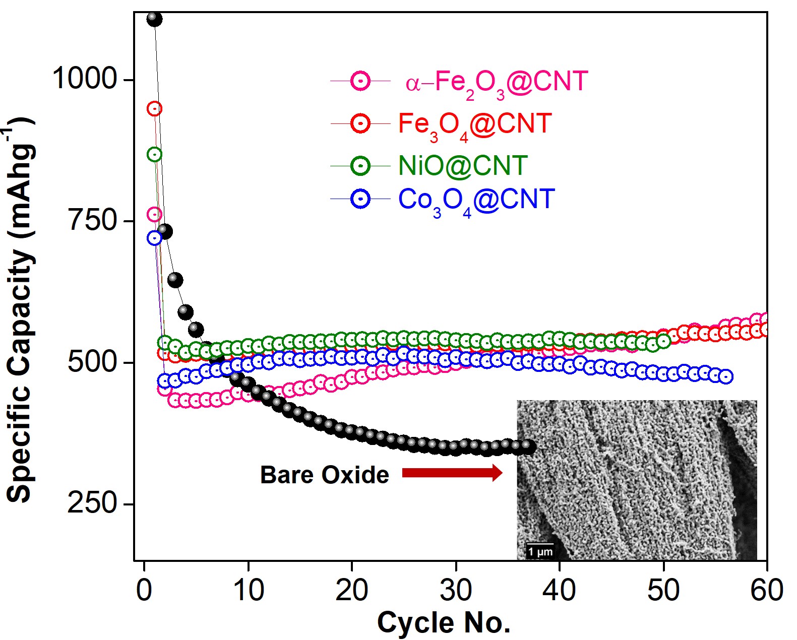
To confirm that superior cyclic stability in these Oxides@CNT nano-structures arises from encapsulation within the core cavity of the CNT, we conducted control measurements on the bare-oxide. Here the representative bare-oxide (-Fe2O3) is formed in the same morphology as Fe2O3@CNT by suitable annealing Kapoor et al. (2019). The bare-oxide template was obtained from the same batch of Fe2O3@CNT, on which electrochemical measurements were performed. This enables us to check and isolate the effect of the morphology of the active material on the cyclic stability. These data, in conjunction with all Oxides@CNT are presented in Figure 5. The morphology of the representative bare-oxide is shown in the inset of Figure 5. The morphologies of other Oxides@CNT are shown in the inset of Figure 2 and Figure 4(b).
The black dots in Figure 5 display the cycling performance of bare oxide template, which is Fe2O3 at a current density of 100 mA g-1. The specific capacity of bare oxide template drops down from 1100mA h g-1 at first cycle to 350 mA h g-1 after 35 cycles, thus, exhibiting a poor stability.Ji et al. (2011) The primary reason for poor cyclic stability of the bare oxide materials in LIBs is known to arise from pulverization of the anode material. The drastic volume variations during metal to metal-oxide conversions leads to strain effects during the cyclic process, which together with low electrical conductivity in bare oxide leads to poor cycle lifeJi et al. (2011). Fe2O3@CNT, on the other hand exhibits superior cyclic stability (pink dots in Figure 5) and cycle capacity retention. It is also evident that bare oxide (-Fe2O3 in this case) exhibit poor cyclic stability as compared to not only Fe2O3@CNT but all other Oxides@CNT, presented in Figure 5. These oxides@CNT contain different type of oxide encapsulate with varying filling fractions and density of residue oxide NP. More importantly, data is on Oxides@CNT samples formed in different types of morphologies, such as aligned-forests or entangled. Nevertheless, all these oxides@CNT exhibit superior cyclic stability as compared to the bare-oxides. Thus, encapsulation of oxides within the core cavity of CNT accommodates strain related to metal to metal-oxide conversion.Yan et al. (2013) It appears that factors such as filling fraction, residue oxide NP and overall morphology of the oxide@CNT can play an important role in tuning the magnitude of specific capacity. Some of these factors need optimization: for instance, the entangled morphology may be more conducive to Li-ion transportation, but the aligned-forests morphology, owing to better connectivity of the CNT network leads to improved conductance.
IV Conclusions
We have conducted comprehensive electrochemical measurements on samples of carbon nanotubes, in which four different type of transition metal oxides have been encapsulated. This includes Fe3O4@CNT, Fe2O3@CNT, NiO@CNT, and Co3O4@CNT; all of which have been synthesized in desired morphology to optimize best parameters for LIBs. The samples have been characterized using X-Ray diffraction, Raman, Thermogravimetric analysis, Scanning and Transmission Electron Microscopy. These characterization tools enable us to correlate the structural aspects including morphology of the CNT network, filling efficiency, and the residue particle density with the electrochemical data. The electrochemical performance is investigated using a coin cell as well as a Swagelok-type of cell configurations. Our data enables us to conclude that Oxides@CNT deliver a superior cyclic stability as compared to bare-oxides. The excellent stability and high capacity of Oxides@CNT can be attributed to the introduction of carbon nanotube structures that contain the oxide within its core cavity. The graphitic shells of the CNT buffer the volumetric strain effects that take place during metal to metal-oxide conversion and improves the electrical conductivity, consequently resulting in excellent cycling performance. The CNT also protects the electrode materials from pulverization, which in-turn offers long-term stability of the electrode materials. We observe that the morphology of the CNT network also plays an important role. The entangled morphology of the CNT network with reasonable filling efficiency and control on the residue oxide nano-particles leads to good cyclic stability as well as higher capacity. This systematic study enables optimization of best parameters for the usage of these synthetically encapsulated and self-organized Oxides@CNT nano-structures for electrochemical applications.
Acknowledgments
The authors thank Mr. J. Parmar, Mr. S.C. Purandare and Mr. R. Bapat (TIFR) for TEM measurements; Mr. Anil Shetty (IISER-P) for SEM, Miss Edna Joseph (NCL, Pune) for TGA measurements. The authors also thank F. Wilhelmi and L. Deeg for experimental support. AB acknowledges DST, India for funding support through a Ramanujan Grant. SO and AB acknowledge DST Nano mission Thematic Unit Grant.
Competing Interests
The authors declare no competing interests.
References
- Goodenough and Park (2013) J. B. Goodenough and K. Park, J. Am. Chem. Soc. 135, 1167 (2013).
- Peters et al. (2017) J. F. Peters, M. Baumann, B. Zimmermann, J. Braun, and M. Weil, Renewable and Sustainable Energy Reviews 67, 491 (2017).
- Hameer and van Niekerk (2015) S. Hameer and J. L. van Niekerk, Int. J. Energy Res. 39, 1179 (2015).
- Aravindan et al. (2015) V. Aravindan, Y. S. Lee, and S. Madhavi, Adv. Energy Mater. 5, 1402225 (2015).
- Ji et al. (2011) L. Ji, Z. Lin, M. Alcoutlabi, and X. Zhang, Energy Environ. Sci. 4, 2682 (2011).
- Zhang and A.Yu (2015) J. Zhang and A.Yu, Sci. Bull. 60, 823 (2015).
- Zheng et al. (2018) M. Zheng, H. Tang, L. Li, Q. Hu, L. Zhang, H. Xue, and H. Pang, Adv. Sci. 5, 1700592 (2018).
- Tian et al. (2018) C. Tian, F. Lin, and M. M. Doeff, Acc. Chem. Res. 51, 89 (2018).
- Cao et al. (2017) K. Cao, T. Jin, L. Yanga, and L. Jiao, Mater. Chem. Front. 1, 2213 (2017).
- Zhang et al. (2011) D. Zhang, A. Qian, J. Chen, J. Wen, L. Wang, and C. Chen, Ionics 18, 591 (2011).
- Fan et al. (2017) L. Fan, W. Zhang, S. Zhu, and Y. Lu, Ind. Eng. Chem. Res. 56, 2046 (2017).
- Liu and Wang (2014) H. Liu and G. Wang, J. Mater. Chem. A 2, 9955L (2014).
- Reddy et al. (2007) M. V. Reddy, T. Yu, C. H. Sow, Z. X. Shen, C. T. Lim, G. V. S. Rao, and B. V. R. Chowdari, Adv. Funct. Mater. 17, 2792 (2007).
- Li et al. (2016) Q. Li, G. Huang, D. Yin, Y. Wu, and L. Wang, Part. Part. Syst. Charact. 33, 764 (2016).
- Pang et al. (2016) Y. Pang, J. Zhang, D. Chen, and X. Jiao, RSC Adv. 6, 30395 (2016).
- Song and Ma (2018) N. J. Song and C. Ma, Int. J. Electrochem. Sci. 13, 452 (2018).
- Wang et al. (2018) Y. Wang, Z. Wang, X. Yub, B. Li, F. Kang, and Y. B. Hea, J. Mater. Res. 33, 1058 (2018).
- Wua et al. (2012) Z. S. Wua, G. Zhoua, L.-C. Yina, W. Rena, F. Lia, and H. M. Chenga, Nano Energy 1, 107 (2012).
- Zhao et al. (2017) Y. Zhao, L. P. Wang, M. T. Sougrati, Z. Feng, Y. Leconte, A. Fisher, M. Srinivasan, and Z. Xu, Adv. Energy Mater. 7, 1601424 (2017).
- Jiang et al. (2017) T. Jiang, F. Bu, X. Feng, I. Shakir, G. Hao, and Y. Xu, ACS Nano 11, 5140 (2017).
- Yang et al. (2011) Z. Yang, J. Shen, and . . L. A. Archer 21, 2011, J. Mater. Chem. 21, 11092 (2011).
- Wang et al. (2017) G. Wang, Y. Meng, L. Wang, et al., Int. J. Electrochem. Sci. 12, 2618 (2017).
- Xu et al. (2018) Y. Xu, S. Hou, G. Yang, T. Lu, and L. Pan, J Solid State Electrochem 22, 785 (2018).
- Yan et al. (2013) N. Yan, X. Zhou, Y. Li, F. Wang, H. Zhong, H. Wang, and Q. Chen, Sci. Rep. 3, 3392 (2013).
- Zhou et al. (2016) H. Zhou, L. Zhang, D. Zhang, S. Chen, P. R. Coxon, X. He, M. Coto, H. K. Kim, K. Xi, and S. Ding, Sci. Rep. 6, 37752 (2016).
- Zhang et al. (2010) W. D. Zhang, B. Xu, and L. C. Jiang, J. Mater. Chem. 20, 6383 (2010).
- Cao and Wei (2015) Z. Cao and B. Wei, Front. Mater. 2 (2015).
- Ottmann et al. (2017) A. Ottmann, M. Scholz, M. Haft, E. Thauer, P. Schneider, M. Gellesch, et al., Sci. Rep. 7, 13625 (2017).
- Puthusseri et al. (2016) D. Puthusseri, V. Aravindan, S. Madhavi, and S. Ogale, Energy Technology 4, 816 (2016).
- Tang et al. (2019) X. Tang, M. Liang, Y. Zhang, W. Sun, and Y. Wang, Dalton Trans. 48, 4413 (2019).
- Liu et al. (2017a) Y. Liu, N. Wu, Z. Wang, H. Cao, and J. Liu, New J. Chem. 41, 6241 (2017a).
- Ottmann et al. (2020) A. Ottmann, L. Deeg, R. Ghunaim, et al., Journal of Alloys and Compounds 834, 155018 (2020).
- E.Thauer et al. (2020) E.Thauer, A. Ottmann, P. Schneider, et al., Molecules 25, 1064 (2020).
- Choi et al. (2015) S. H. Choi, J. H. Lee, and Y. C. Kang, ACS Nano 9, 10173 (2015).
- Bahadur et al. (2018) A. Bahadur, S. Iqbal, M. Shoaib, et al., Dalton Transactions (2018).
- Wang et al. (2016) X. Wang, X. Liu, G. Wang, et al., Mater. Chem. A 4, 18532 (2016).
- Cao et al. (2016) W. Cao, A. Hu, X. Chen, et al., Electrochimica Acta 213, 75 (2016).
- Cheng et al. (2013) J. Cheng, B. Wang, C. M. Park, et al., Chem. Eur. J. 19, 9866 (2013).
- Liu et al. (2017b) Y. Liu, N. Wu, Z. Wang, et al., New J. Chem. 41, 6241 (2017b).
- Kapoor et al. (2018) A. Kapoor, N. Singh, A. B. Dey, A. Nigam, and A. Bajpai, Carbon 132, 733 (2018).
- Kapoor et al. (2019) A. Kapoor, A.B.Dey, C. Garg, et al., Nanotechnology , 385706 (2019).
- Ottmann et al. (2015) A. Ottmann, G. Zakharova, B. Ehrstein, et al., Electrochim Acta 174, 682 (2015).
- Dillon et al. (2012) F. Dillon, A. Bajpai, A. Koos, et al., Carbon 50, 3674 (2012).
- Peci and Baxendale (2016) T. Peci and M. Baxendale, Carbon 98, 519 (2016).
- Saito et al. (1998) R. Saito, G. Dresselhaus, and M. S. Dresselhaus, (London: Imperial College Press, 1998).
- de Faria et al. (1997) D. L. A. de Faria, S. V. Silva, and M. T. de Oliveira, Journ. Ram. Spect. 28, 873 (1997).
- Mironova-Ulmane et al. (2011) N. Mironova-Ulmane, A. Kuzmin, I. Sildos, et al., Cent. Eur. J. Phys. 9, 1096 (2011).
- Hadjiev et al. (1988) V. Hadjiev, M. Iliev, and I. Vergilov, J. Phys. C: Solid State Phys. 21, 199 (1988).
- Luo et al. (2013) J. Luo, J. Liu, Z. Zeng, C. F. Ng, L. Ma, H. Zhang, J. Lin, Z. Shen, and H. J. Fan, Nano Lett. 13, 6136 (2013).
- Chen et al. (2013) T. Chen, L. Pan, X. Liu, et al., Mater Chem. Phys. 142, 345 (2013).
- Huang et al. (2017) Y. Huang, Z. Xu, J. Mai, T. K. Lau, X. Lu, Y. Hsu, et al., Nano Energy 41, 426 (2017).