Three-dimensional matter-wave interferometry of a trapped single ion
Abstract
We report on a demonstration of Ramsey interferometry by three-dimensional motion with a trapped 171Yb+ ion. We applied a momentum kick to the ion in a direction diagonal to the trap axes to initiate three-dimensional motion using a mode-locked pulse laser. The interference signal was analyzed theoretically to demonstrate three-dimensional matter-wave interference. This work paves the way to realizing matter-wave interferometry using trapped ions.
The wave nature of matter offers the potential of measuring physical quantities with high precision. Matter-wave interferometers normally exploit entanglement between the internal state and the motional state of matter. The accumulated matter-wave phases for different paths are derived from the interference signal of the internal states after the closing pulse of the interferometer. Since atoms and ions provide us with exquisite control of individual quanta using electronic, magnetic and optical means, they have been widely used as wave-like matters in many sensing applications. Neutral atom systems have been extensively used and there are a large number of demonstrations of precision sensing such as in measurement of the relativistic effects in electromagnetic interactions [1, 2, 3], atomic and molecular properties [4, 5], and measurement of inertial displacement [6, 7, 8, 9, 10, 11].
In contrast, a quantum sensing based on a matter-wave interference with trapped ions has so far not been demonstrated. In an ion trap, the Schrödinger cat state, which is the quantum superposition of classically distinct states, was realized for the first time for a laser-cooled ion prepared in the motional ground state [12]. Later, a scheme to create the cat state using ultrashort pulses from a mode-locked laser was realized, and spin-motion entanglement was created on a short time scale [13, 14, 15, 16]. This has also been achieved with ions in the thermal regime [17, 18, 19]. Campbell and Hamilton recently proposed a scheme to utilize a trapped ion in such a Schrödinger cat state for a precise rotation sensing [20]. In their proposal, an ion undergoing two-dimensional circular motion is utilized to construct a Sagnac interferometer. Compared with neutral atom gyroscope, the ions with multiple circular motions make a large effective interferometer area with a compact physical size and also relatively immune to the change of acceleration. To realize the gyroscope with trapped ion in the future, interferometry for ions in motion along multiple symmetry axes is an important next step for the new types of sensing applications.
In this Letter, we demonstrate a matter-wave interferometry of a trapped ion in a three-dimensional motion, initiated by a momentum kick in a direction diagonal to any of the trap symmetry axes. We applied pulse to the ion, which puts it into a superposition state made up of the original spin state and motion, and the opposite spin state with additional momentum due to the momentum kick. This spin-motion coupling is applied along the three symmetry axes of the trap simultaneously, and half of the ion wave packet travels with a harmonic potential relative to the other half of the ion wave packet in the original spin and motion state. In the experiment, we applied second pulse after the interrogation time to close the interferometer. When the interrogation time of this Ramsey type interferometer is an integer multiple of the trap period, constructive interference is observed. Since trap frequencies for the three axes are different, the interference signal shows a complicated interrogation-time dependence. A slight change in the frequency of one of the trap axes causes a sensitive change in the interference signal, indicating that the interference arises from ion motion in three dimensions. We theoretically analyzed the interference signal and found good agreement between the measured data and the theory. We estimated the rotation sensing sensitivity assuming that the ion has a circular orbit with the current experimental parameters. Based on the evaluation, we mentioned our present system’s proposal to the application of the gyroscope.
We trapped a single 171Yb+ ion using a linear Paul trap. We used a mode-locked frequency-tripled Nd:YVO4 laser with a pulse duration of ps, a center wavelength of nm, and a repetition rate MHz [15, 16]. The laser drove stimulated Raman transitions between the two hyperfine ground states and to give momentum kicks to the ion. Acousto-optic modulators (AOMs) were placed in both optical paths and were used to tune the frequency difference between the two beams to match the hyperfine splitting , where is the frequency shift generated by the AOMs. We chose , and 354 MHz. Each optical path had the same length to arrive the pulse train at the ion simultaneously. All of 355 nm beam paths were covered with a case to prevent fluctuations of the beam spot position due to air flow.
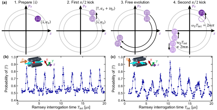
By introducing the pulse trains from opposite directions along the axial trap axis shown in the inset of Fig. 1(b), a one-dimensional momentum kick was given to the ion along the axial trap axis. Figure 1(a) depicts the position-momentum phase space in the one-dimensional interference experiment. First, the ion was prepared in a state using Doppler cooling and optical pumping. Therefore, the ion motional state is thermal, and is expressed as a superposition of coherent states. For simplicity, we express the initial state as a coherent state (step 1 in Fig. 1(a)). Next, we applied a pulse using a 200 ns long pulse train. This pulse train is in the strong excitation regime [21], and applies the same momentum kick for each coherent state contained in the thermal state. The momentum kick causes the ion to transfer to a superposition state (step 2), where is the Lamb-Dicke parameter, is the difference in wave vector between the two beams, is the Ytterbium mass, and is the trap frequency of direction. After an interrogation time (step 3), we applied a /2 pulse again, which partially transfers the state to a state with added momentum , and transfers the state to a state with added momentum (step 4). Finally we detected the probability of the ion being in the state.
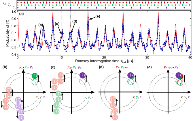
Figure 1(b) shows the transition probability from state to state as a function of the interrogation time between two pulses for a one-dimensional momentum kick. As can be clearly seen, constructive interference appears at integer multiples of the trap period () determined by the axial trap frequency kHz. After the second /2 pulse for ( is the integer in step 4 in Fig. 1(a)), the transition probability reaches 0.8 when the two wave packets match, but is only around 0.5 when the wave packets did not match for . In Fig. 1(b), the measured transition probability for the peaks is smaller than unity, because of imperfect Rabi oscillations due to the finite temperature.
Next, under the same trap conditions, we changed the direction of the momentum kick to along the direction diagonal to all trap axes. The results are shown in Fig. 1(c). Peaks appear at integer multiples of the trap period, similar to the case for one-dimensional matter-wave interference in Fig. 1(b). However, peak height variations from 0.6 to 0.9 are observed in this configuration, in contrast to the results shown in Fig. 1(b); this is a clear indication of three-dimensional interference.
In order to clarify this complicated motion, we theoretically investigated three-dimensional matter-wave interference using a previously reported method [16, 22]. In our experimental scheme, we apply pulse to the ion. Therefore the pulse train operator becomes:
| (1) |
Here is the harmonic oscillator displacement operator in phase space which moves coherent state to another coherent state with momentum transfer, and is an optical phase offset assumed it constant. After applying two pulses with the time interval between pulse trains, the probability of detecting the ion in the state after the interference process can be expressed as:
| (2) |
where describes the wave function overlap along the axes:
| (3) |
Here is the mean phonon number in the direction.
To investigate the result of three-dimensional interferometry in detail, we observed the interference with a longer interrogation time. Figure 2(a) displays the results for interference initiated by the diagonal momentum kick. The red solid line shows the results of fitting using Eq. (2). The red, green, and purple diamonds at the top of each figure show the timing when integer multiples of , and , respectively, are obtained. Three trap frequencies , and the ion temperature contained in were taken as free parameters. From the fitting results, the trap frequencies were obtained to be kHz and the ion temperature was 2.23(6) mK. On the other hand, we also measured radial trap frequency from the spectroscopy, the results were kHz, respectively. Also, we measured the calibration curve of axial trap frequency based on sideband spectroscopy, and the result corresponding to the condition of the measurement in Fig. 2(a) was kHz. Hence, the fitting results of trap frequencies of three axes approximate to the measurement results using sideband spectroscopy and the calibration curve.
Figures 2(b–e) show phase-space diagrams for the ion for the timings shown in Fig. 2(a). At time (b), is an integer multiple of the trap period along the axis (), but not along the and axes (, ). Constructive interference is not observed because the wave packets are in different positions along the and axes in the harmonic potential.
When is an integer multiple of (at time (c)), constructive interference is observed even though is not an integer multiple of and . The difference between times (b) and (c) arises from the fact that the trajectory along the axis is bigger than that along the and axes, due to the difference in the strength of the momentum kick and the trap confinement strength 111The momentum kick strength along axis is larger by a factor of than that along the and axes, and the trap is shallower along the axis by a factor of 2.5 compared with the and axes.. At the time (e) when is approximately commensurate with all three trap periods, the strongest peak appears due to perfect wave packet overlap. However, at the peaks the measured results were smaller than the calculated values, this is caused the imperfection of the spin flip due to the high ion temperature.
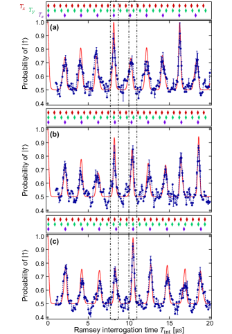
To further investigate the three-dimensional interference, values of 491.7(1) kHz, 484.0(3) kHz, and 474.8(3) kHz were used, as shown in Fig. 3. The radial trap and values of each experiment obtained from the fitting were (a) 1229.0(8) kHz and 1349.7(9) kHz, (b) 1229(2) kHz and 1346(2) kHz, (c) 1234(2) kHz and 1335(2) kHz, respectively. Please pay attention to the peaks around 8.2 s and 10.2 s (the area surrounded by a dashed line). The peak near 8.2 s decreases as increases. At kHz, a large interference signal is observed because the timing of the 4th period of , the 11th period of , and the 10th period of , are matching. By changing to kHz, the timing of the 4th period of does not match, and the interference signal strength is reduced. In contrast, the peak near 10.2 s increases as increases because the timing of the 5th period of , the 14th period of , and the 13th period of match at 474.8 kHz.
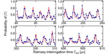
We next investigated the coherence time for three-dimensional ion motion. Figure 4 shows the three-dimensional interference for various ranges of . In order to take into account the coherence time, we added an attenuation factor into the second term of Eq. (2). Each red solid curve in Fig. 4 is a best fit to the experimental results for each interrogation time for a fixed ion temperature and attenuation coefficient . The results indicate that the decoherence time is 3.3(5) ms. Even for large values up to 600 s, the interference signal is well reproduced by the theoretical curves, indicating that the coherence of ion motion in all directions decays over the same time scale.
In the current work, the multi-dimensional matter-wave interference was demonstrated in an anisotropic trapping potential, and therefore the ion was traveling in a Lissajous orbit. To apply the current system for rotation sensing, a circular ion motion needs to be realized by tuning the confinement strength of the trap to make the trap potential isotropic in two dimensions. Assuming that we realize an isotropic potential in the current trap condition, the expected sensitivity of the gyroscope is , which is eight orders of magnitude worse than the conventional ring laser gyroscope. Since the spatial separation of two wave packets in the current experiment is only on the order of 1 nm, which is the same scale with the zero point width, the sensitivity is quite limited. The sensitivity can be improved by adding much larger momentum kicks to the ion by increasing the number of pulses [18], reducing the trap confinement strength, and applying the displacement of the trap center [20]. With these contrivances, our system will attain the same accuracy as the ring laser gyroscope. Since the dynamics of the ion during the interrogation time reflects the imperfections of matter-wave interferometers [24], the full understanding of the free time evolution of an ion is an important ingredient for improving the sensitivity of the matter-wave interferometers.
We acknowledge fruitful discussion with Mikio Kozuma and Ryotaro Inoue. This work was supported by JST-Mirai Program Grant Number JPMJMI17A3, Japan.
References
- Zeiske et al. [1995] K. Zeiske, G. Zinner, F. Riehle, and J. Helmcke, Applied Physics B 60, 205 (1995).
- Görlitz et al. [1995] A. Görlitz, B. Schuh, and A. Weis, Phys. Rev. A 51, R4305 (1995).
- Yanagimachi et al. [2002] S. Yanagimachi, M. Kajiro, M. Machiya, and A. Morinaga, Phys. Rev. A 65, 042104 (2002).
- Ekstrom et al. [1995] C. R. Ekstrom, J. Schmiedmayer, M. S. Chapman, T. D. Hammond, and D. E. Pritchard, Phys. Rev. A 51, 3883 (1995).
- Schmiedmayer et al. [1995] J. Schmiedmayer, M. S. Chapman, C. R. Ekstrom, T. D. Hammond, S. Wehinger, and D. E. Pritchard, Phys. Rev. Lett. 74, 1043 (1995).
- Kasevich and Chu [1991] M. Kasevich and S. Chu, Phys. Rev. Lett. 67, 181 (1991).
- Oberthaler et al. [1996] M. K. Oberthaler, S. Bernet, E. M. Rasel, J. Schmiedmayer, and A. Zeilinger, Phys. Rev. A 54, 3165 (1996).
- Riehle et al. [1991] F. Riehle, T. Kisters, A. Witte, J. Helmcke, and C. J. Bordé, Phys. Rev. Lett. 67, 177 (1991).
- Peters et al. [1999] A. Peters, K. Y. Chung, and S. Chu, Nature 400, 849 (1999).
- Gustavson et al. [1997] T. L. Gustavson, P. Bouyer, and M. A. Kasevich, Phys. Rev. Lett. 78, 2046 (1997).
- Gustavson et al. [2000] T. L. Gustavson, A. Landragin, and M. A. Kasevich, Classical and Quantum Gravity 17, 2385 (2000).
- Monroe et al. [1996] C. Monroe, D. M. Meekhof, B. E. King, and D. J. Wineland, Science 272, 1131 (1996).
- Campbell et al. [2010] W. C. Campbell, J. Mizrahi, Q. Quraishi, C. Senko, D. Hayes, D. Hucul, D. N. Matsukevich, P. Maunz, and C. Monroe, Phys. Rev. Lett. 105, 090502 (2010).
- Hayes et al. [2010] D. Hayes, D. N. Matsukevich, P. Maunz, D. Hucul, Q. Quraishi, S. Olmschenk, W. Campbell, J. Mizrahi, C. Senko, and C. Monroe, Phys. Rev. Lett. 104, 140501 (2010).
- Mizrahi et al. [2013] J. Mizrahi, C. Senko, B. Neyenhuis, K. G. Johnson, W. C. Campbell, C. W. S. Conover, and C. Monroe, Phys. Rev. Lett. 110, 203001 (2013).
- Mizrahi et al. [2014] J. Mizrahi, B. Neyenhuis, K. G. Johnson, W. C. Campbell, C. Senko, D. Hayes, and C. Monroe, Applied Physics B 114, 45 (2014).
- Johnson et al. [2015] K. G. Johnson, B. Neyenhuis, J. Mizrahi, J. D. Wong-Campos, and C. Monroe, Phys. Rev. Lett. 115, 213001 (2015).
- Johnson et al. [2017] K. G. Johnson, J. D. Wong-Campos, B. Neyenhuis, J. Mizrahi, and C. Monroe, Nature Communications 8, 697 (2017).
- Wong-Campos et al. [2017] J. D. Wong-Campos, S. A. Moses, K. G. Johnson, and C. Monroe, Phys. Rev. Lett. 119, 230501 (2017).
- Campbell and Hamilton [2017] W. C. Campbell and P. Hamilton, J. Phys. B: At. Mol. Opt. Phys. 50, 064002 (2017).
- Poyatos et al. [1996] J. F. Poyatos, J. I. Cirac, R. Blatt, and P. Zoller, Phys. Rev. A 54, 1532 (1996).
- Mizrahi [2013] J. A. Mizrahi, Ultrafast control of spin and motion in trapped ions, Ph.D. thesis (2013).
- Note [1] The momentum kick strength along axis is larger by a factor of than that along the and axes, and the trap is shallower along the axis by a factor of 2.5 compared with the and axes.
- West [2019] A. D. West, Phys. Rev. A 100, 063622 (2019).