Full Attitude Intelligent Controller Design of a Heliquad under Complete Failure of an Actuator
Abstract
In this paper, we design a reliable Heliquad and develop an intelligent controller to handle the complete failure of one actuator. Heliquad is a multi-copter similar to Quadcopter, with four actuators diagonally symmetric from the center. Each actuator has two control inputs; the first input changes the collective pitch of the propeller blades (also called variable pitch), and the other input changes the rotation speed. For reliable operation and to handle high torque characteristic requirement for yaw control, a cambered airfoil is used to design propeller blades. A neural network based based control allocation is designed to provide complete control authority even under a complete loss of one actuator. Nonlinear quaternion based outer loop position control, with proportional-derivative inner loop for attitude control and neural network-based control allocation is used in controller design. The proposed controller and Heliquad design’s performance is evaluated using a software-in-loop simulation to track the position reference command under failure. The results clearly indicate that the Heliquad with an intelligent controller provides necessary tracking performance even under a complete loss of one actuator.
Keywords: Mechanics and Control, Vehicle Dynamics, Fault tolerant control, Variable pitch propeller , Cambered airfoil.
I INTRODUCTION
Sensor technological development in vertical take-off and landing (VTOL) rotorcraft UAVs are gaining attention in a wide range of applications fire-fighting [1, 2], agriculture [3], search mission [4]. UAV’s have recently found application in outdoor use such as geologic and construction mapping [5, 6]. Recently, quadcopters are used for aggressive maneuvering in a cluttered indoor environment [7], high-speed flight in GPS denied indoor environments [8], and passenger carrying vehicles [9].
In all the above applications, robustness and reliability of multi-rotor are important. In particular, robustness against actuator failure is crucial. Actuators are prone to failure anytime during the mission due to some unforeseen faults. Control under partial loss of effectiveness is investigated in [10],[11]. The use of frames that have inherently redundant motors such as hexacopter and octocopter can deal with complete loss of actuator [12]. However, these approaches are expensive and larger in size, making them difficult to navigate in a cluttered environment. Parachute based recovery is used in some commercial UAV rotor-crafts 111DJI Dropsafe, https://www.dji.com/dropsafe. However, while operating above a hostile area (for example, a large water body), it may not be possible to directly descend after actuator failure. The vehicle should track some position references, get over a safe area, and then descend. Reduced attitude control for Quadcopter requires sacrificing control over the yaw angle because of the non-existence of an equilibrium point [13, 14]. Hence, Quadcopter may not be possible for safety-critical payload.
Variable pitch application on the Quadcopter is present in literature for about a decade. Benefits of variable pitch actuation over standard fixed-pitch such as high actuator bandwidth, generation of negative thrust, and sustained inverted flight, are presented in [15]. A detailed dynamic model considering the influence of generalized motion on the propeller’s aerodynamics is analyzed in [16]. Nonlinear dynamic inversion control for trajectory tracking is investigated in [17]. However, in this case, vehicle design permits only controlling pitch angles on each actuator, keeping RPM constant. The aforementioned variable pitch Quadcopter provides flexibility but does not provide control authority under an actuator’s complete failure.
In this paper, we design a Heliquad that can provide necessary controllability under failure and develop an intelligent full attitude controller to provide necessary tracking performance under the complete loss of a single actuator. The Heliquad has a similar design as that of a Quadcopter. The propeller employs a cambered airfoil for the propeller and actuator, controlling both the propeller’s pitch and rotation speed. An intelligent flight control includes nonlinear quaternion based outer-loop position control, proportional-derivative based inner-loop attitude control, and neural network-based control allocation approach. The performance of the proposed controller and Heliquad design is evaluated using a software-in-loop simulation. The results clearly indicate that the proposed intelligent control can provide complete control authority even under the complete loss of a single actuator.
The paper is organized as follows: Heliquad design, along with it is modeling, is described in section II. Controller design, along with its novel intelligent control allocation, is discussed in Section III. Multibody and software-in-loop simulations are presented in section IV. Conclusions and remarks on future work are given in section V.
II Heliquad Design and Modelling
The Heliquad is a portmanteau formed from helicopter and Quadcopter. The Heliquad’s exterior look is similar to a conventional Quadcopter, but the only difference is in the actuation. Control thrust can be manipulated by varying each motor’s speed like a Quadcopter or changing the propeller collective pitch angle like a helicopter or both. Heliquad employs a brushless DC motor to control the propeller’s speed, and a servo motor to change the pitch through a bar chain mechanism (as shown in Fig. 1). The research presented in the existing literature on the use of variable pitch actuation in quadcopter makes the use of symmetric airfoil in propeller blades [16, 15]. Such multicopters can provide high maneuverability but do not provide necessary controllability under failure.
In this section, first we model the actuators used on Heliquad, then we provide conditions to achieve equilibrium when one actuator completely fails. Next, propeller aerodynamics is modelled using first principles. Subsequently we show the impracticality of commercially available symmetric airfoil variable pitch propellers to achieve static equilibrium under complete failure of one actuator. At the end, solution to this problem is presented by incorporating cambered airfoil in the propeller design.
II-A Actuator modelling for variable pitch
Electric motors are used as actuators and are modelled using the standard equations available in literature [18]. Brushless DC motor dynamics is given by
| (1) |
where is the input voltage, is no-load current of the motor, is internal resistance, is the voltage constant for the motor. is the opposing torque acting on motor. The servo motor is used to control pitch angle and is modeled as a rate limit of deg/s. It is assumed that there is no backlash in the pitch actuation mechanism, hence allowing a direct map between the servo head angle and propeller pitch. The motor parameters are given in Table. I.
| Parameters | Values |
|---|---|
| (volts) | 12 |
| (rad/s-V) | 900 |
| (Ohms) | 0.09 |
| (Amp) | 0.5 |
II-B Static equilibrium with three operating actuators
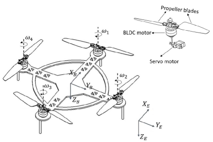
Static equilibrium or hover is possible in fixed-pitch Quadcopter when the vehicle weight is balanced by the collective thrust produced by four propellers and torque generated by two opposite working propellers is nullified by other sets of propellers. Complete failure of one actuator induces asymmetry in the design. Without loss of generality, it is assumed that actuator is not working (refer Fig .1). To maintain equilibrium, following conditions must be satisfied.
| (2) |
| (3) |
| (4) |
| (5) |
where, and are the thrust and torque produced by propeller respectively, is the weight of Heliquad. If total thrust-to-weight ratio of vehicle is greater than or equal to two then it is possible to satisfy Eq. (2) and Eq. (3) The use of variable pitch actuator can qualitatively satisfy conditions Eq. (4) and Eq. (5) because of it is the ability to produce zero thrust and non-zero torque simultaneously. However, propeller aerodynamics will play an important role in the feasibility of satisfying the above conditions.
II-C Propeller aerodynamics
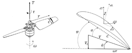
The propeller aerodynamics is analyzed using the Blade Element Momentum Theory (BEMT) [16]. We assume minimal external wind, hence elemental thrust () force acting on airfoil section located at distance from the center of rotation and rotating with angular velocity about it is given by Blade Element Theory (BET) as
| (6) | |||||
| (7) |
where
| (8) | |||||
| (9) |
where, and are elemental lift and drag force acting on propeller blades (refer Fig. 2). These forces act perpendicular and parallel to velocity vector respectively. The term is air density (1.22 ), and are lift and drag coefficients of airfoil used in propeller, is Reynolds number. Note, is the chord length of section. The elemental torque () is given by
| (10) |
Equation (7) has two unknowns namely and . In order to solve these unknowns, we use momentum theory to relate in terms of . The relationship is given by
| (11) |
where
| (12) |
where, is prandtl’s tip loss correction factor [19] and is number of blades. Equation (7) and Eq. (11) are solved iteratively for each input and to find corresponding unknown . The known can be substituted back in Eq. (7) and Eq. (10), and integrated over radius of propeller to find thrust and torque respectively.
Note that many combinations of control inputs and that can generate desired thrust. High propeller pitch angle can generate desired thrust by keeping low RPM, same magnitude of thrust can be generated by setting propeller pitch to lesser value but increasing motor RPM. In the interest of satisfying equations (2)-(5), optimal choice of control inputs and for actuator and would be the one that gives desired thrust with minimum torque so that propeller can counteract it with less effort.
II-D Comparison between symmetric and cambered airfoil propeller
Let the nominal all-up weight of Heliquad to be grams and simulated BEMT to find the equilibrium control inputs. For this simulation, we judiciously chose commercially available EVP-2216 motor-propeller combination. This propeller has symmetrical airfoil. Based on simulation results, we found out that in order to satisfy conditions (2)-(5), motor opposite to failed one needs to spin at around RPM. At this speed, the propeller generates enough torque to maintain yaw equilibrium. However, the required speed of motor is beyond the practical limit of RPM [15]. One of the solutions to this problem is to change the airfoil (cross-section) geometry of the propeller.
To show the importance of airfoil, the Eq. (7) assume to be small and ,
| (13) |
Similarly,
| (14) |
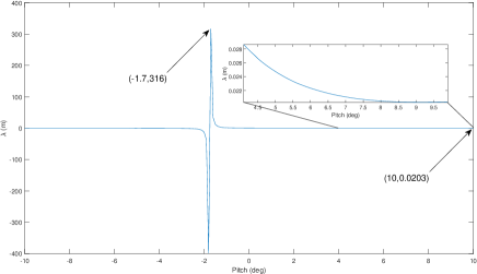
It can be seen that thrust and torque are heavily influenced by airfoil lift and drag coefficients respectively. Let be the pitch angle at which thrust produced is zero. Based on Eq. (11), will be zero when . Similarly, based on Eq. (9), . The term is angle-of-attack at which coefficient of lift is zero. Note that the term is negative value for cambered airfoil. Hence , by setting pitch angle at , the propeller will be able to generate zero thrust irrespective of rotor speed.
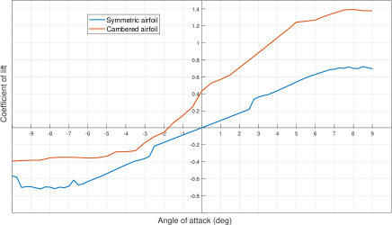
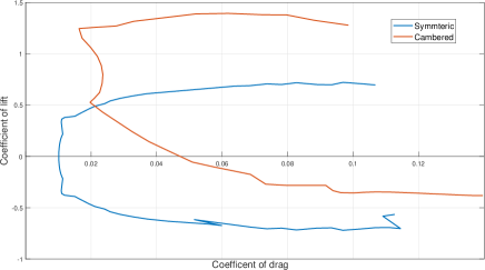
Let is coefficient of drag when coefficient of lift is zero (when airfoil operates at AOA of ). Symmetric airfoils by its characteristic has significantly lesser compared to cambered airfoils, whereas there is no significant difference between at higher . This characteristic of cambered airfoil is vital for satisfying equilibrium condition. The propeller using cambered airfoil will provide significantly more torque when pitch angle is set to .
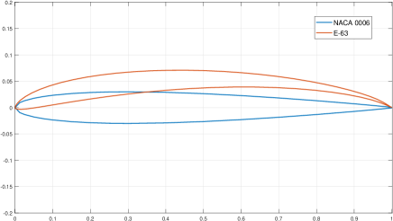
In Fig. 3, we compare NACA 0006 (symmetric) and Eppler E-63 (cambered) airfoils. Note, these airfoils are used in some commercially available variable pitch 222Evp2216.”ttps://www.aliexpress.com/item/32822544022. and fixed pitch propellers respectively 333APC propellers https://www.apcprop.com/technicalinformation/engineering.. In Fig.3(c) it can be seen that for cambered airfoil is around , whereas it is for symmetric one. Eq.(14) shows that, for same propeller size and , at cambered airfoil will generate approximately times more torque than symmetric airfoil propeller. Due to it’s high drag characteristics which are required for yaw control, the proposed Heliquad uses a E-63 cambered airfoil in its propeller blades. Geometric dimensions of the blades are same as of commercially available one.
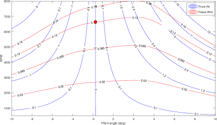
Results of BEMT simulations on E-63 airfoil propeller are shown in Fig. (4). In this case to satisfy Equation (2)-(5), under nominal weight, and corresponding . and can be achieved by setting to -1.8 and to 6620 RPM. By using cambered airfoil, RPM required to achieve hover equilibrium has reduced to practical value.
The weight of Heliquad plays an important role in the failed actuator scenario. As the weight goes down, the red dot in Fig. 4 slides vertically downwards, giving more yaw control authority. This happens because two opposite working actuators will produce less thrust to balance the weight, which would generate less torque, reducing the actuator’s effort opposite the failed one. The detailed weight distribution of the heliquad is shown in Table II. Other physical parameters are given in Table III. where is distance between frame’s geometric centre and propeller centre of rotation. is the notation for moment of inertia about body frame axis. Heliquad’s dynamics is similar to any other conventional fixed pitch quadcopter where Newton-Euler rigid body equations are used. More details regarding dynamics of Heliquad can be found in supplementary material. The control allocation becomes really challenging because of strong nonlinearities in propeller aerodynamics.
| Part | Value (gms) | Quantity | Weight (gms) |
|---|---|---|---|
| Motor+prop | 80 | 4 | 320 |
| Servo motor | 9 | 4 | 36 |
| Payload | 50 | 1 | 50 |
| Battery(850mah) | 70 | 1 | 70 |
| Other electronics | 50 | 50 | |
| Frame | 76 | 1 | 76 |
| Total | 602 |
| Parameters | Value | Units |
|---|---|---|
| 0.1794 | m | |
III INTELLIGENT CONTROLLER DESIGN
The paper employs a typical outer-loop position tracking and inner-loop attitude control scheme similar to [15]. The proposed control scheme employs an intelligent control allocation to handle nominal and faults conditions. First, we present control architecture and then present an intelligent control allocation scheme.
III-A Control architecture
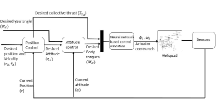
The schematic diagram of control architecture is shown in Fig. 5. The outer loop controller will give the desired collective thrust vector based on position and velocity errors. In contrast, the inner loop proportional derivative controller will give the desired body torque vector required to track and the desired yaw angle. Based on the condition, the intelligent control allocation scheme provides the desired speed for individual actuators.
The desired collective thrust vector () is
| (15) | |||||
| (16) |
where is current position, and are tuneable gains. .
Output of inner loop attitude control is desired body moments which are given by
| (17) | |||||
| (18) |
error quaternion vector which represents angle between and , and are desired and current body rate vectors respectively, and are tuneable gains. More details on inner-loop attitude control can be found in [15]
III-B Intelligent Control Allocation
An intelligent control allocation scheme is developed handle the nominal condition and fault conditions. Based on the condition, the control allocation scheme generate desired speed to individual actuator. For this purpose, we employ a neural network to approximate the relationship between the inputs () and output .
III-B1 Control allocation for nominal operation
For nominal operation, the pitch angle () for all four propellers are fixed at same value. We choose the value of which allows sufficient margins over both RPM and . Hence, control allocation will be similar as in standard fixed-pitch Quadcopter. Thus, the control inputs are only the RPM of each motor. A parameter which is the ratio of torque to thrust produced by propeller is denoted as,
| (19) |
Note, the parameter is invariant of RPM, it just depends on . The desired thrust forces () for each actuator are calculated as follows,
| (20) |
In the above equation as per our strategy . The desired thrust, torque and pitch angle are passed as input to four separate control allocation neural network to obtain the respective desired .
III-B2 Control allocation for faulty operation
In failed actuator scenario, bounds are introduced on just before control allocation. With respect to limits due to actuator saturation, tighter bounds are required . Bounds on the desired collective thrust depends on the required yaw control authority. As increases, torque generated by two opposite working propeller also increases, hence propeller opposite to failed rotor has to provide more torque to overcome it and keep desired margin. When actuator 4 experiences failure, maximum permitted can be written as
| (21) |
In the above equation, RHS is the maximum possible torque propeller can provide without generating any thrust.
In case of fault condition, we assume that there exist a fault detection mechanism which provide input to control allocation block. Based on the fault, the following steps are used to generate necessary input to control allocation neural network.
-
Step. 1
Let us fix the pitch () for opposite working propellers at same value. We choose the value of pitch angle that generates desired thrust and keeps torque lowest. In other words, should be lowest. As two opposite working propellers generate less torque, propeller opposite to failed one has to work less to balance it or to track desired yaw moments. Figure (6) shows that does not vary much at higher pitch angles, so any value of pitch angle which gives sufficient margin on desired RPM can be chosen.
-
Step. 2
The reduced control allocation matrix (RCAM) is a invertible matrix which gives desired thrust vector based on desired roll pitch moments and collective thrust. Each of the four failure scenarios will have different RCAM’s. For example RCAM when actuator fails
(22) -
Step. 3
Torque that needs to be generated by propeller opposite to failed rotor to meet desired yaw moment is calculated.
-
Step. 4
Desired for rotor opposite to failed one is calculated by taking ratio of desired torque to thrust.
-
Step. 5
A 1D Look-Up-Table (LUT) is developed to approximate data in Fig. 6. This LUT will be used to get based on input .
-
Step. 6
Using ,, as inputs to control allocation neural network we get the desired rotor speed for each motor.
III-B3 Control allocation neural network
In order to handle the nonlinearities in propeller aerodynamics, we propose a control allocation neural network which approximate the relationship between and desired speed () for the actuator. The architecture of the control allocation neural network is shown in Fig. 7 with number of hidden neuron. The approximated is given as
| (23) |
where
| (24) |
is a tanhyperbolic activation function.
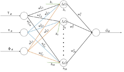
The training data for control allocation network is generated using BEMT for different number of inputs and . Instead of explicitly providing uncertainty, we ignore tip loss factor in Eq. (11) while generating data. Standard levenberg-marquardt backpropogation algorithm is used to train weights () and biases (). The number of hidden neurons are selected using the procedure described in [20].
IV Performance Evaluation
Software in the loop simulations were conducted to validate our control strategy. Control architecture is designed in MATLAB® Simulink ®. Detailed vehicle CAD model was developed to model vehicle dynamics in multi-body environment of Simscape TM. Propeller aerodynamic model developed in section II-C was validated for positive pitch angles using propeller analysis software QPROP [18]. QPROP does not converge for negative pitch angles.
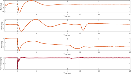
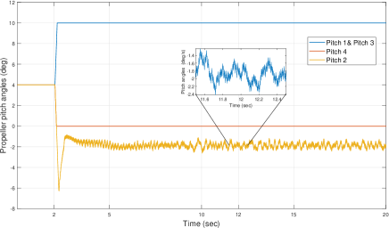
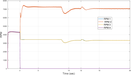
Heliquad is dropped from 10 meters of altitude. To model the failure, RPM of actuator number is instantaneously switched off at time-step sec. Vehicle is allowed to stabilize itself and reach desired height of m before changing position reference command to meter at second. It is assumed that it takes milliseconds for fault detection and isolation. Before failure, pitch angles of all four propellers are set at degrees, after failure propeller pitch of rotor number and are fixed at degrees, pitch of propeller is changed as per control allocation method discussed in previous section. Gains of the controller are tuned to provide necessary tracking.
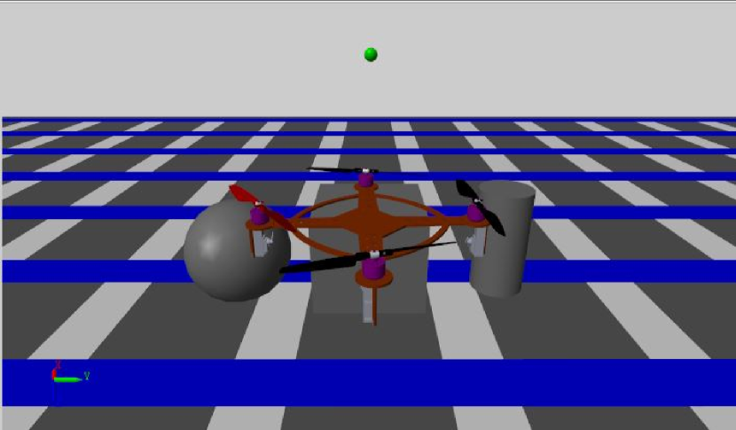
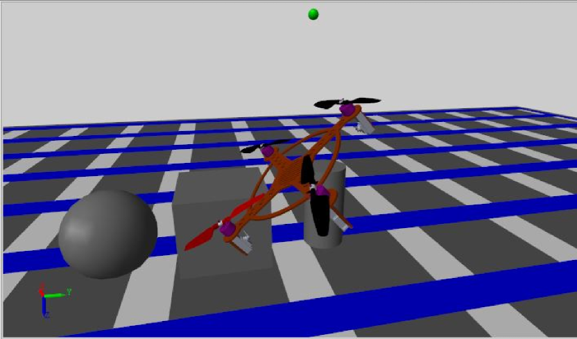
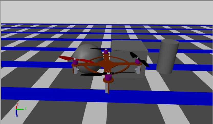
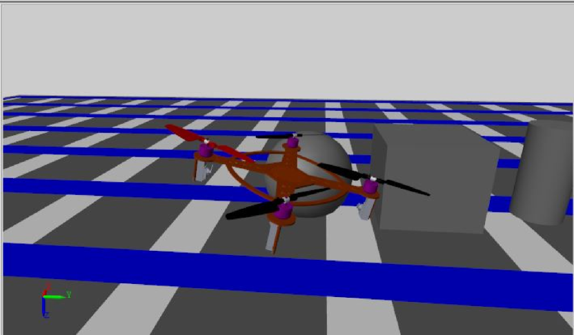
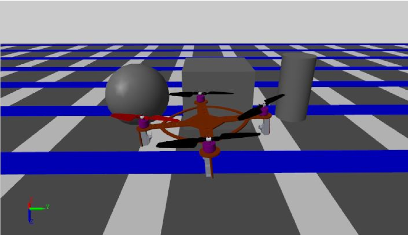
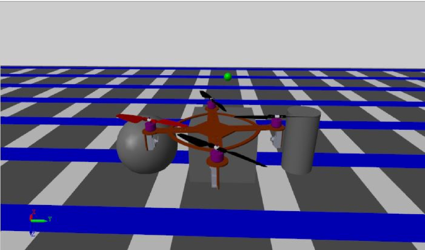
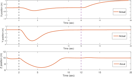
Fig.9 shows the position tracking ability of Heliquad. Before failure Heliquad is commanded to maintain position , after failure it takes around seconds to return back to hover mode (refer Fig. 8). Just at the start, small initial dip in the altitude is because of zero initial motor speeds, it will take some time to build up required RPM. After the failure at seconds Heliquad looses approximately m altitude before climbing again. Climbing performance degrades because of limits imposed on collective thrust in Eq. (21). At seconds desired position reference is changed to . It can be seen that controller is able to track position references satisfactorily. In Fig. 10, because of delay assumed in fault detection roll angle will increase rapidly. Fault is detected when roll angle is around degrees. Despite this, controller is able to stabilize it back to hover equilibrium. Fig. 10 also confirms the Heliquad’s unique ability to bring back yaw rate to zero despite complete failure of one actuator. Fig .11 shows the pitch angle of propellers. Just after failure, pitch assumes large negative value to generate reverse thrust needed to counter the adverse roll rate. After attaining equilibrium, Pitch oscillates about ( deg). Fig. 12 shows that till failure all four motors spin at almost same RPM, after failure as propeller pitch on and is set at higher values ( deg each) hence they require less RPM to satisfy desired thrust. In contrast, motor spins at higher RPM to satisfy required yaw moment. RPM’s of all the motors are within limit. Results of fault scenario when fault occurs while Heliquad is maneuvering are given in supplementary materials.
V CONCLUSION
This paper proposes a new variable pitch Quadcopter with cambered airfoil called Heliquad and intelligent control architecture to handle the complete failure of a single actuator. The presence of a cambered airfoil in a variable pitch propeller helps the Heliquad to produce the necessary thrust and torque to handle failure cases. The control allocation neural network captures the nonlinear relationship in propeller aerodynamics on the torque and speed. Using the nonlinear quaternion outer loop position control and inner loop, proportional-derivative attitude control provides necessary thrust requirements. The control allocation neural network determines the pitch and speed inputs to actuators. The performance of the Heliquad is evaluated using a software-in-loop multi-body simulation. The results clearly indicate that the proposed Heliquad can handle single actuator failure and provide necessary tracking performances. Since airfoil used in propeller plays an important role, the future work analyzes different airfoil section to improve the performance of Heliquad and conduct flight test validate the performance.
References
- [1] K. Harikumar, J. Senthilnath, and S. Suresh, “Mission aware motion planning (map) framework with physical and geographical constraints for a swarm of mobile stations,” IEEE Transactions on Cybernetics, vol. 50, p. 1209–1219, 03 2020.
- [2] K. Harikumar, J. Senthilnath, and S. Suresh, “Multi-uav oxyrrhis marina-inspired search and dynamic formation control for forest firefighting,” IEEE Transactions on Automation Science and Engineering, vol. 16, pp. 863–873, 02 2018.
- [3] P. Katsigiannis, L. Misopolinos, V. Liakopoulos, T. K. Alexandridis, and G. Zalidis, “An autonomous multi-sensor uav system for reduced-input precision agriculture applications,” in 2016 24th Mediterranean Conference on Control and Automation (MED), pp. 60–64, 2016.
- [4] M. Bejiga, A. Zeggada, A. Nouffidj, and F. Melgani, “A convolutional neural network approach for assisting avalanche search and rescue operations with uav imagery,” Remote Sensing, vol. 9, p. 100, Jan 2017.
- [5] B. Jordan, “A bird’s-eye view of geology: The use of micro drones/uavs in geologic fieldwork and education,” GSA Today, vol. 25, pp. 42–43, 07 2015.
- [6] S. Siebert and J. Teizer, “Mobile 3d mapping for surveying earthwork projects using an unmanned aerial vehicle (uav) system,” Automation in construction, vol. 41, pp. 1–14, 2014.
- [7] B. Landry, R. Deits, P. R. Florence, and R. Tedrake, “Aggressive quadrotor flight through cluttered environments using mixed integer programming,” in 2016 IEEE international conference on robotics and automation (ICRA), pp. 1469–1475, IEEE, 2016.
- [8] K. Mohta, M. Watterson, Y. Mulgaonkar, S. Liu, C. Qu, A. Makineni, K. Saulnier, K. Sun, A. Z. Zhu, J. Delmerico, K. Karydis, N. Atanasov, G. Loianno, D. Scaramuzza, K. Daniilidis, C. J. Taylor, and V. Kumar, “Fast, autonomous flight in gps-denied and cluttered environments,” J. Field Robotics, vol. 35, pp. 101–120, 2018.
- [9] C. Silva, W. R. Johnson, E. Solis, M. D. Patterson, and K. R. Antcliff, “Vtol urban air mobility concept vehicles for technology development,” in 2018 Aviation Technology, Integration, and Operations Conference, p. 3847, 2018.
- [10] M. Ranjbaran and K. Khorasani, “Fault recovery of an under-actuated quadrotor aerial vehicle,” in 49th IEEE Conference on Decision and Control (CDC), pp. 4385–4392, IEEE, 2010.
- [11] N. P. Nguyen and S. K. Hong, “Fault-tolerant control of quadcopter uavs using robust adaptive sliding mode approach,” Energies, vol. 12, p. 95, Dec 2018.
- [12] G. P. Falconí, J. Angelov, and F. Holzapfel, “Hexacopter outdoor flight test results using adaptive control allocation subject to an unknown complete loss of one propeller,” in 2016 3rd Conference on Control and Fault-Tolerant Systems (SysTol), pp. 373–380, 2016.
- [13] A. Freddi, A. Lanzon, and S. Longhi, “A feedback linearization approach to fault tolerance in quadrotor vehicles,” IFAC Proceedings Volumes, vol. 44, no. 1, pp. 5413 – 5418, 2011. 18th IFAC World Congress.
- [14] M. W. Mueller and R. D’Andrea, “Stability and control of a quadrocopter despite the complete loss of one, two, or three propellers,” in 2014 IEEE international conference on robotics and automation (ICRA), pp. 45–52, IEEE, 2014.
- [15] M. Cutler and J. P. How, “Analysis and Control of a Variable-Pitch Quadrotor for Agile Flight,” Journal of Dynamic Systems, Measurement, and Control, vol. 137, no. 10, 2015. 101002.
- [16] V. S. chipade, A. Abhishek, and M. Kothari, “Advanced flight dynamic modelling of variable pitch quadrotor,” in 2018 AIAA Atmospheric Flight Mechanics Conference, pp. 1763–1779, 2018.
- [17] N. Gupta, M. Kothari, et al., “Flight dynamics and nonlinear control design for variable-pitch quadrotors,” in 2016 American Control Conference (ACC), pp. 3150–3155, IEEE, 2016.
- [18] M. Drela, QPROP Documentation, 2006. http://web.mit.edu/drela/Public/web/qprop/.
- [19] J. G. Leishman, Principles of helicopter aerodynamics. Cambridge aerospace series, 12, Cambridge University Press, 2nd ed ed., 2006.
- [20] M. Kumar, S. Omkar, R. Ganguli, P. Sampath, and S. Suresh, “Identification of helicopter dynamics using recurrent neural networks and flight data,” Journal of the American Helicopter Society, vol. 51, no. 2, pp. 164–174, 2006.