) \xspaceaddexceptions]
The influence of strut waviness on the tensile response of lattice materials
Abstract
Recent advances in additive manufacturing methods make it possible, for the first time, to manufacture complex micro-architectured solids that achieve desired stress versus strain responses. Here, we report experimental measurements and associated finite element (FE) calculations on the effect of strut shape upon the tensile response of two-dimensional (2D) lattices made from low-carbon steel sheets. Two lattice topologies are considered: (i) a stretching-dominated triangular lattice and (ii) a bending-dominated hexagonal lattice. It is found that strut waviness can enhance the ductility of each lattice, particularly for bending-dominated hexagonal lattices. Manufacturing imperfections such as undercuts have a small effect on the ductility of the lattices but can significantly reduce the ultimate tensile strength. FE simulations provide additional insight into these observations and are used to construct design maps to aid the design of lattices with specified strength and ductility.
1 Introduction
Recent advances in manufacturing methods [1, 2] have facilitated the manufacture of lattice materials with complex topologies over a wide range of length scale. This class of materials is used in a large variety of engineering applications, e. g. tower structures in civil engineering, the cores of lightweight sandwich panels, and microscopic mechanical filters [3]. In the present study, we consider the tensile behaviour of 2-dimensional (2D) triangular and hexagonal lattices. This choice of lattice topology is motivated by the broad range of their mechanical properties: stretching-dominated triangular lattices have high in-plane stiffness and strength whereas hexagonal lattices are compliant, bending-dominated structures [4, 5]. Wavy struts of sinusoidal shape are introduced in order to modify the macroscopic stress versus strain response of each lattice.
1.1 Tensile deformation of lattice materials
Two-dimensional (2D) lattices of triangular and hexagonal geometry comprise struts of node-to-node length and in-plane strut thickness . The macroscopic properties of these lattices scale with their relative density , as defined by the ratio of volume occupied by solid material to the total volume of the lattice. For straight slender struts, the relative density scales linearly with the stockiness of each strut according to
| (1) |
where the coefficient depends upon the architecture of the lattice ( equals for triangular lattices and for hexagonal lattices [6]). It is evident that, for the same value of , triangular lattices have a greater density than to hexagonal lattices. Note that Eq. 1 is an approximation as it neglects the volume of the nodes of the lattice but it suffices for low relative densities (typically ).
Consider a lattice made from elastic, perfectly plastic cell walls of elastic modulus and yield strength . Then, the macroscopic in-plane modulus and yield strength of an infinite periodic lattice scale with via the relations [6]
| (2) |
where , , , and for the triangular lattice and , , , and for the hexagonal lattice [6, 7].
While Eqs. (2) characterise the small strain response, the response under finite deformations is more complex. For example, the uniaxial tensile response of an elastoplastic hexagonal lattice exhibits four regimes, as discussed by Tankasala et al. [5] and Ronan et al. [8]. The sequence of deformation modes with increasing applied macroscopic strain are: (i) elastic bending of struts, (ii) plastic bending of struts (iii) elastic stretching of struts as the inclined struts rotate towards loading direction, and finally (iv) plastic stretching of the struts aligned with the loading direction. In contrast, triangular lattices deform by stretching at low levels of applied strain and exhibit three regimes: (i) elastic stretching of struts, (ii) plastic stretching and rotation of the struts towards the direction of macroscopic straining, and (iii) a final regime involving stretching of struts that are aligned with the loading direction [5]. Failure may intervene during any of these regimes depending upon the properties of the cell wall material.
1.2 Classes of lattices
Typically, lattices are bending-dominated (hexagonal) or stretching-dominated (triangular) structures. Furthermore, each strut can comprise a finer-scaled lattice, with a bending or stretching response at this lower length scale [9]. The following cases are considered in this study:
-
(i) stretching lattice:
A triangular lattice possesses a sufficiently high nodal connectivity () that the lattice is stretching-dominated. Provided each strut is straight, deformation of the lattice induces stretching of each strut and thus we shall refer to the topology as stretching on the lattice scale as well as stretching on the strut scale. Such a lattice has a high modulus and inherits the ductility of the cell wall material [10].
-
(ii) stretching-bending lattice:
Now consider a stretching-dominated lattice such as the triangular lattice, with struts which have enhanced axial compliance due to waviness of the struts. We refer to such a lattice as a stretching-bending lattice.
-
(iii) bending lattice:
A hexagonal lattice with straight struts deforms by bending of the struts. The presence of strut waviness has a negligible effect upon the bending stiffness of the strut and thereby has a negligible effect upon the macroscopic compliance. We refer to this lattice as a bending lattice.
1.3 Imperfections in struts
The sensitivity of modulus, strength, and ductility to imperfections within a foam or a lattice has been studied systematically, see for example [6, 8, 11, 12, 13, 5, 7, 14, 15, 16, 17]. Imperfections include missing struts, misaligned struts, misplaced joints, Plateau borders and cell-level inclusions for the case of metallic foams [8]. Recently, the sensitivity of the dispersion in macroscopic properties to the statistical distribution of imperfections has been analysed for brittle [18] and visco-plastic honeycombs [19] made by rapid prototyping: a scatter in strut thickness and in strut ductility have a major detrimental effect on the macroscopic strength.
1.4 Influence of strut waviness on macroscopic properties
Wavy struts can have a profound influence on the macroscopic properties of lattice materials: lattices comprising wavy struts allow tuneable Poisson’s ratio [20] and macroscopic stiffness [21]. Symons et al. [11] and Grenestedt [22] predicted the influence of sinusoidal strut waviness on the macroscopic stiffness of triangular, stretching-dominated lattices. The axial stiffness of a strut with such waviness of amplitude is [11]
| (3) |
where is the strut thickness, the node-to-node strut length and is the axial modulus of the parent material. Thus, a waviness amplitude leads to a knock-down in the axial stiffness of the strut by a factor of 25 and consequently there is a similar knock-down in the overall modulus of a triangular lattice comprising such wavy struts. While waviness reduces lattice stiffness it can enhance lattice ductility. For example, Ma et al. [23, 24] and Jang et al. [21] investigated polyimide lattices materials comprising horseshoe-shaped struts embedded in a soft polymeric matrix. The inherent waviness of the horseshoe shaped struts significantly enhanced the ductility of these lattices.
1.5 Scope of study
The aim of the current study is to investigate lattice designs that deliver desired ductilities and ultimate strengths. We constructed two-dimensional (2D) steel lattice materials of constant relative density and made from wavy struts. Detailed measurements of the tensile responses of the lattice materials, their manufacturing induced defects and their constituent materials are reported. The measurements are accompanied by FE simulations that include the observed manufacturing defects. The combined effect of strut waviness and manufacturing defects is mapped out by FE simulations for both the bending-dominated and stretching-dominated lattices to give guidelines for the design of lattice materials comprising wavy struts.
2 A preliminary assessment of the significance of undercut and waviness
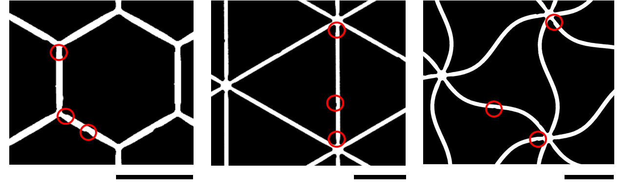
A major focus of this study is to understand the interplay between as-designed “imperfections” such as strut waviness, and typical as-manufactured defects. A preliminary examination of steel hexagonal and triangular lattices manufactured by water-jet cutting revealed the presence of undercuts near joints; see the 3-dimensional (3D) computerised tomography (CT) scan images shown in Fig. 1 for both triangular and hexagonal lattices. Here we report a finite element (FE) assessment of these undercuts by modelling their effect on the tensile response of a single straight strut or wavy strut.
Consider a two-dimensional (2D) strut of length , in-plane thickness , sinusoidal waviness of amplitude and out-of-plane thickness (Fig. 1). We introduce an undercut into this strut at a distance from one end of the strut, with the undercut characterised by its radius and depth as shown in Fig. 1. The plane strain tensile response of the strut was analysed via FE simulations using the commercial finite element package Abaqus. The strut was discretised by quadratic elements (CPE8 in the Abaqus notation) with 10 elements across the strut thickness. The solid material is idealised by a deformation theory solid with a tensile stress versus strain response parameterised by the Ramberg-Osgood relationship
| (4) |
with the choice of parameters , reference strength , and hardening exponent . A monotonically increasing axial displacement was applied to the strut until the conjugate load reached a peak value associated with necking of the strut. Peak load defines the onset of failure of the strut.
Predictions of the normalised load versus normalised displacement are included in Fig. 1 for a strut of aspect ratio . The figure includes predictions for both a straight strut () and a wavy strut of sinusoidal shape with a wavelength and amplitude , such that . Results are given for two choices of normalised undercut depth and , with the normalised undercut radius and position held fixed at and , respectively.
First, consider the case with no undercut (). The straight strut has an initial sharply rising load versus displacement response. The response then displays a plateau as the strut material undergoes plastic deformation. In contrast, the wavy strut has a sigmoidal load-displacement response: initially, the wavy strut straightens by bending. Thereafter, the response is similar to that of the straight strut. The predictions in both cases are terminated at peak load (marked by a cross) corresponding to the onset of necking of the strut.
Second, consider the case of the struts with an undercut . The load-displacement response up to the onset of necking is identical to that with no undercut. The undercut induces early necking at the location of the undercut and the location of the peak load is marked by the cross on the curves in Fig. 1. We define the peak load as the failure load and the corresponding displacement as the failure displacement. A cross-plot of the normalised failure load versus the normalised failure displacement is included in Fig. 1 for both the straight strut and strut with , for selected undercut depths ; and are held fixed at 0.5 and , respectively. The failure load is largely unaffected by waviness and increases with decreasing undercut depth. However, the failure displacement for a given undercut depth increases sharply with increasing waviness and also increases with decreasing undercut depth (corresponding to the increase in the failure load). These results are insensitive to the choice of undercut radii and locations over a broad range of values ( and ). We proceed to use this basic understanding to investigate first experimentally and then numerically the design of lattice materials with prescribed strut waviness.
3 Experimental programme
Specimens were manufactured by water-jet cutting of hot-rolled mm thick steel sheets of grade S275 (low carbon steel with a maximum of 0.25% of carbon by weight) and hardness 185HV30. Three different specimen types were employed: (i) macroscale dogbone specimens (Fig. 2) of the parent material to characterise the solid material properties; (ii) specimens that replicate the geometry of single struts within the lattices (Figs. 2 and 2) and (iii) triangular and hexagonal lattice specimens (Figs. 2 and 2) of relative density .
The tensile response at a nominal tensile strain rate of s-1 was measured using a screw-driven test machine, with the load cell of the machine used to measure the applied tensile load . A laser extensometer was used to measure the gauge section extension of the dogbone parent material specimens while Digital Image Correlation (DIC) was used to measure displacements in the single strut and lattice specimens.
3.1 Geometry of struts and the single strut specimens
The struts of the lattices investigated here were either straight (S) or wavy. Two wavy geometries were employed: (i) a single sinusoidal (SS) waveform and (ii) a decaying sinusoidal (DS) waveform. These waveforms are parameterised as follows. In the local Cartesian co-ordinate system , the equation parameterising the SS waveform is
| (5) |
where is the amplitude of the wavy strut, and the wavelength is the distance between the end points of the strut; see Fig. 3. The DS waveform retains the symmetry of the SS waveform about the mid-span of the strut and is parameterised by
| (6) |
where the factor of has been included to ensure that the maximum amplitude of the waviness equals as seen in Fig. 3.
In order to investigate the tensile responses of these struts within the lattices, we also manufactured single strut specimens as shown in Figs. 2 and 2. These specimens comprise either straight or wavy struts and comprised the same node geometries as are present in the triangular and hexagonal lattices.
3.2 Lattice specimens
The tensile response of triangular and hexagonal lattices comprising straight and wavy struts was investigated using dogbone shaped specimens (Figs. 2 and 2) to ensure that failure occurred within the gauge section. The gauge section of the triangular and hexagonal lattice specimens comprised and cells, respectively. The specimens were bolted to 3 mm thick steel end tabs to enable gripping of the specimens for tensile loading. The specimens were manufactured by water-jet cutting of the 3 mm thick steel sheets, with the tensile loading direction of the specimens aligned with the rolling direction of the steel sheets. The radius of the water-jet nozzle was 0.34 mm and thus the corner radii of the nodes exceeds 0.34 mm.
All lattice specimens investigated here had a relative density . While the relative density of lattices with straight struts is only a function of , the magnitude of for lattices with wavy struts depends strongly on the strut shape. It is instructive to define the arc-length of a strut with node-to-node length as
| (7) |
where is the local, Cartesian co-ordinate system and the -direction is co-incident with a straight strut between the nodes. The modified form of Eq. 1 for lattices with wavy struts is then
| (8) |
For all lattices investigated here we kept , and and 0.09 for the triangular and hexagonal lattices, respectively, independent of the strut shape, so that in all cases. The specific geometric parameters of all lattice geometries investigated here are listed in Table 1.
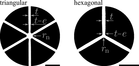
While the water-jet cutting of the lattice used a computed aided drawing (CAD) input111Software to generate the wavy lattice geometries: [25]. of the detailed specimen geometry absent any defects, changes in the cutting speed of the water-jet as it went around the corners of the lattice and residual stresses within the steel sheet meant that the as-cut lattice did not precisely match the CAD specification. X-ray CT examination of the manufactured lattices revealed a dispersion in the strut thicknesses , a finite radius of corners at nodes, and undercuts within the struts near the nodes (see Fig. 1). The X-ray CT images were used to characterise these defects by making measurements over 280 struts in 14 different specimens and the findings of these measurements are summarised as follows:
-
1.
While the mean strut thickness at mid-span attained the specified value of 0.81 mm, the strut thicknesses in each specimen were normally distributed with a standard deviation of .
-
2.
The corner radii were also normally distributed, with a mean value mm and standard deviation of .
-
3.
Nearly all struts had undercuts near the nodes, as characterised by a mean radius and undercut depths in the range ; see Fig. 1 for the definitions of and .
4 Material characterisation
4.1 Solid material response
The material properties of solid low-carbon steel sheets were measured from the response of a large dogbone-shaped specimen of gauge dimensions and (see Fig. 2) at and to the hot-rolling direction of the steel sheets. The measured true stress versus true strain responses of the solid dogbone specimens are shown in Fig. 4. All specimens respond in a ductile manner with a negligible effect of the hot-rolling direction upon the tensile response, such that the Young’s modulus is , yield strength is , ultimate tensile strength is and the nominal tensile failure strain is . Over a strain range , the true stress versus true strain response is well-approximated by where .
4.2 Single strut response
The tensile responses of single struts, of the same geometry as that used in the triangular and hexagonal lattices, are given in Fig. 5. The measured nominal stress, , defined in terms of the measured tensile load , is plotted in Fig. 5 as a function of nominal strain , where is the applied axial displacement responses of the struts. In Fig. 5 the responses are plotted for the struts that are representative of those in the triangular lattices while in Fig. 5 we include measurements for the struts that mimic those in the hexagonal lattices. First, consider the straight struts (S). It is evident that the tensile strength is comparable to the solid material response. However, the ductility of straight struts is knocked down to 0.05 and 0.1 for the struts in the triangular and hexagonal lattices, respectively, compared to the parent material value of . These reduction in ductility of the straight single struts compared to that of the solid material is due premature necking at the undercuts introduced by water-jet cutting near the joints.
Strut waviness brings about a qualitative change to the response. Wavy struts are first straightened before they neck and therefore waviness increases the ductility of single struts, with the largest increase of ductility exhibited by decaying sinusoidal struts (DS). However, the ultimate tensile strength is largely unaffected by the presence of waviness.
5 Finite Element calculations
Static finite element (FE) simulations were performed using Abaqus/Standard v2018 to simulate the tensile response of the single struts and the uniaxial tensile response of the triangular and hexagonal lattices. The 2D plane strain geometry in the FE models mimicked the as-manufactured specimens as observed in the CT images. All struts were ascribed a thickness equal to the mean measured value, mm. In addition, each node of the lattice was assumed to have a corner radius and an undercut of radius . The detailed node geometries were consistent with the CT images, with representative examples for the triangular and hexagonal lattices shown in Fig. 6. The corresponding FE geometries of the lattice specimens, with details of the nodes shown in insets, are included in Figs. 6 and 6 for the triangular and hexagonal lattices, respectively. The undercut depth varied significantly between specimens and the measured values were used in the simulations; their values are explicitly specified in the presentation of the numerical predictions.
The FE mesh of the lattice comprises rectangular elements with quadratic shape functions (CPE8 in Abaqus notation). At least 4 elements across the thickness of each strut were present in order to capture the stress concentration due to the nodes and the undercuts. Uniaxial loading of the lattice specimens was simulated by constraining all degrees of freedom along the bottom edge of the specimen while the top edge is subjected to uniform displacement in the -direction of the specimen, with the -direction displacement of those nodes constrained to be zero, see Figs. 6 and 6. The solid material was modelled as a J2 flow theory solid with Young’s modulus , Poisson’s ratio and a true tensile stress versus plastic strain response given by the measurements in Fig. 4. No damage model was employed in the FE simulations with failure assumed to arise from necking of the struts.
5.1 FE predictions of the tensile response of a single strut
We validated the FE model by comparing predicted and measured single strut responses. The predictions employed a FE model with the single strut modelled in an identical manner to the struts within the lattice specimens. The FE predictions of the tensile responses of the single strut are included in Figs. 5 and 5 for an undercut depth , as measured by X-ray CT. Excellent agreement is observed in all cases including the onset of softening due to necking. This demonstrates the fidelity of the FE model and validates the assumption of not including damage mechanisms in the solid material.
6 Tensile response of lattice specimens: predictions versus experiment
We proceed to present both measurements and FE predictions of the tensile responses of the lattice specimens. Results are presented in terms of a nominal stress and nominal strain where the specimen gauge width and gauge length are defined in Figs. 2 and 2, while and are the applied tensile load and corresponding extension of the gauge length of the specimen, respectively.
The measured nominal stress versus nominal strain responses until first strut failure are in Fig. 7, with the peak load occurring at first strut failure; the macroscopic ductility is defined as , where is the displacement corresponding to the load . The measured mean undercut depths for each specimen are reported in Table 1. In Fig. 7 measurements are included for both triangular (T) and hexagonal (H) lattices with straight (S) struts and wavy struts (), with “SS” and “DS” referring to sinusoidal and decaying sinusoidal shaped struts, respectively. The choice refers to straight (S) struts and this limiting case is included in Fig. 7. The corresponding FE simulations are included for all cases in Fig. 7 and are terminated at the attainment of peak load: similar to the measurements, necking of a strut was detected in the FE simulations at peak load. These FE simulations assumed the measured value of for each specimen listed in Table 1.
-
(i)
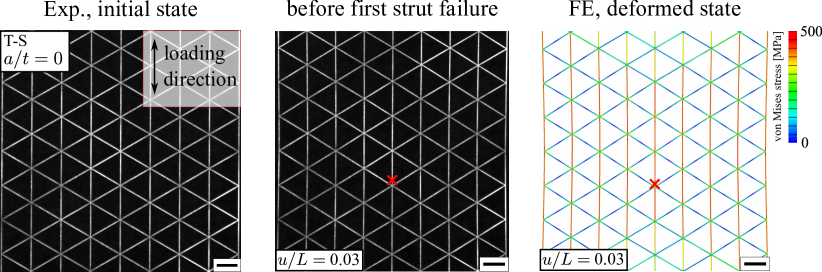
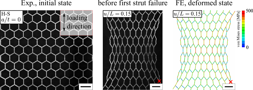
Consider lattices comprising straight struts, with images of the undeformed and deformed triangular and hexagonal lattices shown in Figs. 8 and 9, respectively, along with corresponding FE predictions at peak load; contours of von-Mises stress are shown on the FE images. These lattices behave according to the regimes defined in [5].
The stretch-dominated triangular lattice has a response that can be divided into 3 regimes. In regime I the vertical struts that are aligned with the loading direction undergo elastic stretching while the inclined struts rotate. In regime II, the vertical struts undergo plastic stretching with first failure occurring in these struts due to necking. Since failure occurs in regime II, these measurements do not display a regime III wherein the inclined struts rotate to align with the loading direction [5]. Failure occurs at a relatively low macroscopic strain level and deformation of the lattice at first failure is barely visible as seen in Fig. 8 (the location of the first strut failure is marked in Fig. 8).
For the bending-dominated hexagonal lattices with straight struts (H-S), regimes I and II are characterised by elastic and plastic bending, respectively, of the struts of the lattice. This bending-dominated response implies that the hexagonal lattice has a high initial compliance. Rotation of the inclined struts in regime II aligns them with the loading direction and thereafter the response enters into regime III. In this regime, the struts of the bending-governed hexagonal lattice stretch and then fail by necking. While the ductility of the lattice struts is approximately the same for the triangular and hexagonal lattices the macroscopic strain associated with bending and rotation of the lattice struts endows the hexagonal lattice with a greater ductility than that of the triangular lattice ( and 15 % for the triangular and hexagonal lattices, respectively). Moreover, unlike the triangular lattice (Fig. 8), tensile stretching of the hexagonal lattice involves significant transverse contraction as seen in the deformed images in Fig. 9. This contraction is inhibited by the gripping of the lattice at the top and bottom of the specimens and subsequently we shall show that this results in enhanced stresses in the struts at the edge of the hexagonal lattice specimens. As a consequence, the first strut that fails is at the edge of the specimen (marked in Fig. 9).
-
(ii)
Consider the lattices with wavy struts with the nominal stress versus strain responses given in Fig. 7, and the corresponding images of the deformed lattices given in Figs. 8 and 9. While the peak load decreases only mildly with increasing waviness amplitude , the ductility of both the triangular and hexagonal lattices increase substantially with increasing . Note that the drop in ductility for and 1.3 of T-SS lattices in Fig. 7 is due to the increased undercut depth as reported in Table 1. For a given lattice topology and waviness amplitude , struts of decaying sinusoidal shape result in higher ductility than struts of sinusoidal shape in line with the single strut results of Section 4.2. Also, the bending-dominated hexagonal lattices have a higher ductility than the stretching-dominated triangular lattices. The images in Figs. 8 and 9 show that, at the instant of first strut failure (location marked in both figures), all struts of the hexagonal lattice have lost their waviness by axial stretch while the inclined struts of the triangular lattice retain significant waviness. Failure of the triangular lattices occurs after the waviness in the vertical struts has been eliminated. On the other hand, bending-dominated deformation of the hexagonal lattices implies significant scissoring of the struts; strut stretching, required to neck the struts, initiates only after all struts have aligned with the loading direction and waviness has been eliminated.
The FE predictions of the tensile responses of the lattices are included in Fig. 7 while predictions of the deformed configurations at peak load are presented in Figs. 8 and 9. Recall that the value for each specimen is different and is listed in Table 1. Upon assuming the appropriately chosen value of , excellent agreement is observed between the FE predictions and measurements including the deformed lattice shapes. However, we emphasise that has a strong influence and this is mapped out in detail in Section 7.
6.1 Effect of finite specimen size
The above results suggest that the constraint imposed by the gripping of the specimens results in the development of high stresses in struts along the side edges of the specimens (Fig. 9). This is particularly pronounced for the hexagonal lattices as they have a high value of plastic Poisson’s ratio. Here we use FE simulations to investigate the effect of finite specimen geometry upon the tensile responses of the lattices by contrasting specimen predictions with those of corresponding infinite lattices. The infinite lattices were simulated by considering a representative volume element (RVE) comprising a single unit cell, and uniaxial tension was simulated by imposing periodic boundary conditions on this RVE. All struts in the RVE had an undercut of normalised depth and, in order to make a fair comparison, we also report FE predictions of the tensile responses of lattice specimens (of identical geometry to those considered above) but with all struts in the lattice having an undercut of depth . Predictions are given up to the onset of necking in any strut within the lattice; this point also corresponds to the attainment of peak macroscopic load in the predictions.
Consider the triangular lattice responses shown in Fig. 10 for straight, sinusoidal and decaying sinusoidal strut shapes ( for wavy struts). The difference in responses is small for the finite lattice specimen and infinite lattice although we observe that the infinite lattice has a slightly higher ductility due to a more compliant response just prior to peak load. These results can be contrasted to the corresponding hexagonal lattice predictions included in Fig. 10. While the peak strengths of the infinite and finite hexagonal lattices are approximately equal, the ductility of the infinite lattices is significantly higher in all cases (i. e. straight, sinusoidal and decaying sinusoidal strut shapes). This can be understood from the deformed lattice specimen images in Fig. 9. The constraint of the grips limits the degree of plastic Poisson contraction of the hexagonal lattices, thereby straightening the struts at the specimen sides at smaller applied values of . A consequence of this straightening is a build-up of tensile stress in struts at the specimen sides which in turn results in increasing hardening of the tensile response and premature necking of the edge struts.
7 Design maps
There is a strong interplay between the waviness amplitude and undercut depth that sets the peak strength and ductility . Here we employ FE calculations to explore this interplay for the lattice specimens of Section 6 with the aim of providing guidance on the design of wavy lattices to achieve a specified strength and ductility.
FE predictions of contours of normalised tensile failure strength of the triangular lattice with sinusoidal and decaying sinusoidal shaped struts, are given in Figs. 11 and 11, respectively, in the form of a map with axes of and . Each contour plot is generated by 20 FE simulation. Here, is the failure strength of the lattice for the given choice while is the reference strength of the perfect lattice with . The corresponding predictions for the hexagonal lattice with sinusoidal and decaying sinusoidal shaped struts are given in Figs. 11 and 11, respectively. In all cases, the knockdown in strength, as parameterised by , increases with increasing and ; the waviness amplitude has a larger effect on the hexagonal lattice while the undercut depth plays a more dominant role for the triangular lattices. This is evident from the orientation of the contours.
Next, consider the effect of and upon ductility. FE predictions of contours of the ductility generated by 20 FE simulations are plotted in Fig. 12 on a design map with axes and . The contours of are nearly vertical for the hexagonal lattices (Figs. 12 and 12 for lattices with sinusoidal and decaying sinusoidal shaped struts, respectively) indicating that the presence of the undercut does not significantly degrade ductility. Now consider the contour plots of Figs. 12 and 12 for triangular lattices with sinusoidal and decaying sinusoidal shaped struts, respectively. The contours of become more horizontal at low values of suggesting that the ductility of triangular lattices with nearly straight struts is largely governed by the undercut depth. Consistent with the findings of the experiments and FE simulations reported in Section 6, the maps in Fig. 12 show that hexagonal lattices have a higher ductility than triangular lattices. Moreover, for a given lattice topology, lattices with a decaying sinusoidal shaped struts have a higher ductility then the corresponding lattices with sinusoidal shaped struts.
8 Concluding remarks
Our study has explored, by a combination of measurements and finite element (FE) simulations, the sensitivity of tensile response of bending-dominated hexagonal lattices and stretching-dominated triangular lattices to strut shape. Lattices of relative density were manufactured by water-jet cutting of thick low-carbon steel sheets. Two strut shapes (sinusoidal and decaying sinusoidal) of varying amplitude were investigated, alongside the role of manufacturing defects such as undercuts in the struts near the lattice nodes. Excellent agreement between the measurements and FE simulations allowed us to proceed to employ FE simulations to develop design maps.
An increased strut waviness greatly enhances the ductility of both types of lattice but has a smaller effect upon the peak tensile strength. Moreover, for a given waviness amplitude, the lattices with decaying sinusoidal shaped struts have the highest ductility. The increase in the ductility of stretch-dominated triangular lattices with increased waviness is mainly due to the fact that waviness in the vertical struts needs to be ironed-out prior to them undergoing stretching and then necking. On the other hand, the large rotation of the struts in the bending-dominated hexagonal lattices implies that waviness in all struts needs to be eliminated prior to strut necking. Thus, the ductility enhancement due to waviness is higher in the hexagonal lattices. Imperfections such as undercuts in the lattice strut have a larger effect on the ultimate tensile strength than ductility, and this is demonstrated over a large parameter range via design maps as developed by FE calculations.
The authors gratefully acknowledge the financial support from the European Research Council (ERC) under the European Union’s Horizon 2020 research and innovation program, grant GA669764, MULTILAT.
References
- [1] Tumbleston, J. R., Shirvanyants, D., Ermoshkin, N., Janusziewicz, R., Johnson, A. R., Kelly, D., Chen, K., Pinschmidt, R., Rolland, J. P., Ermoshkin, A., et al., 2015. “Continuous liquid interface production of 3d objects”. Science, 347(6228), pp. 1349–1352.
- [2] Vyatskikh, A., Delalande, S., Kudo, A., Zhang, X., Portela, C. M., and Greer, J. R., 2018. “Additive manufacturing of 3d nano-architected metals”. Nature Communications, 9(1), p. 593.
- [3] Phani, A. S., and Hussein, M. I., 2017. Dynamics of Lattice Materials, Introduction to Lattice Materials. John Wiley & Sons, Ltd, pp. 1–17.
- [4] Hutchinson, R. G., and Fleck, N. A., 2006. “The structural performance of the periodic truss”. Journal of the Mechanics and Physics of Solids, 54(4), pp. 756–782.
- [5] Tankasala, H. C., Deshpande, V. S., and Fleck, N. A., 2017. “Tensile response of elastoplastic lattices at finite strain”. Journal of the Mechanics and Physics of Solids, 109, pp. 307–330.
- [6] Gibson, L. J., and Ashby, M. F., 1999. Cellular solids: Structure and properties. Cambridge University Press.
- [7] Fleck, N. A., and Qiu, X., 2007. “The damage tolerance of elastic–brittle, two-dimensional isotropic lattices”. Journal of the Mechanics and Physics of Solids, 55(3), pp. 562–588.
- [8] Ronan, W., Deshpande, V. S., and Fleck, N. A., 2016. “The tensile ductility of cellular solids: The role of imperfections”. International Journal of Solids and Structures, 102-103, dec, pp. 200–213.
- [9] Fleck, N. A., Deshpande, V. S., and Ashby, M. F., 2010. “Micro-architectured materials: past, present and future”. Proceedings of the Royal Society A: Mathematical, Physical and Engineering Sciences, 466(2121), pp. 2495–2516.
- [10] Gu, H., Pavier, M., and Shterenlikht, A., 2018. “Experimental study of modulus, strength and toughness of 2d triangular lattices”. International Journal of Solids and Structures, 152, pp. 207–216.
- [11] Symons, D. D., and Fleck, N. A., 2008. “The imperfection sensitivity of isotropic two-dimensional elastic lattices”. Journal of Applied Mechanics, 75(5), p. 051011.
- [12] Schmidt, I., and Fleck, N. A., 2001. “Ductile fracture of two-dimensional cellular structures”. International Journal of Fracture, 111(4), pp. 327–342.
- [13] Tankasala, H. C., Deshpande, V. S., and Fleck, N. A., 2015. “2013 Koiter Medal Paper: Crack-Tip Fields and Toughness of Two-Dimensional Elastoplastic Lattices”. Journal of Applied Mechanics, 82(9), p. 091004.
- [14] Romijn, N. E., and Fleck, N. A., 2007. “The fracture toughness of planar lattices: Imperfection sensitivity”. Journal of the Mechanics and Physics of Solids, 55(12), dec, pp. 2538–2564.
- [15] Grenestedt, J., 2005. “On interactions between imperfections in cellular solids”. Journal of Materials Science, 40(22), pp. 5853–5857.
- [16] Liu, L., Kamm, P., García-Moreno, F., Banhart, J., and Pasini, D., 2017. “Elastic and failure response of imperfect three-dimensional metallic lattices: the role of geometric defects induced by selective laser melting”. Journal of the Mechanics and Physics of Solids.
- [17] Tankasala, H. C., and Fleck, N. A., 2020. “The crack growth resistance of an elastoplastic lattice”. International Journal of Solids and Structures, 188-189, pp. 233–243.
- [18] Seiler, P. E., Tankasala, H. C., and Fleck, N. A., 2019. “The role of defects in dictating the strength of brittle honeycombs made by rapid prototyping”. Acta Materialia, 171, pp. 190–200.
- [19] Seiler, P. E., Tankasala, H. C., and Fleck, N. A., 2019. “Creep failure of honeycombs made by rapid prototyping”. Acta Materialia, 178, pp. 122–134.
- [20] Chen, Y., Li, T., Scarpa, F., and Wang, L., 2017. “Lattice Metamaterials with Mechanically Tunable Poisson’s Ratio for Vibration Control”. Physical Review Applied, 7, Feb, p. 024012.
- [21] Jang, K.-I., Chung, H. U., Xu, S., Lee, C. H., Luan, H., Jeong, J., Cheng, H., Kim, G.-T., Han, S. Y., Lee, J. W., Kim, J., Cho, M., Miao, F., Yang, Y., Jung, H. N., Flavin, M., Liu, H., Kong, G. W., Yu, K. J., Rhee, S. I., Chung, J., Kim, B., Kwak, J. W., Yun, M. H., Kim, J. Y., Song, Y. M., Paik, U., Zhang, Y., Huang, Y., and Rogers, J. A., 2015. “Soft network composite materials with deterministic and bio-inspired designs”. Nature Communications, 6, p. 6566.
- [22] Grenestedt, J. L., 1998. “Influence of wavy imperfections in cell walls on elastic stiffness of cellular solids”. Journal of the Mechanics and Physics of Solids, 46(1), pp. 29–50.
- [23] Ma, Q., Cheng, H., Jang, K.-I., Luan, H., Hwang, K.-C., Rogers, J. A., Huang, Y., and Zhang, Y., 2016. “A nonlinear mechanics model of bio-inspired hierarchical lattice materials consisting of horseshoe microstructures”. Journal of the Mechanics and Physics of Solids, 90, pp. 179–202.
- [24] Ma, Q., and Zhang, Y., 2016. “Mechanics of fractal-inspired horseshoe microstructures for applications in stretchable electronics”. Journal of Applied Mechanics, 83(11), p. 111008.
- [25] Seiler, P. E., and Fleck, N. A., 2020. “2-dimensional lattice geometries for rapid prototyping”. Zenodo.
Tables
| lattice geometry | strut shape | |||||
|---|---|---|---|---|---|---|
| triangular | straight (T-S) | 0 | 0.030 | 1.00 | 0.03 | 0.2 |
| 0.7 | 0.030 | 1.01 | 0.03 | 0.3 | ||
| sine (T-SS) | 1.3 | 0.029 | 1.02 | 0.03 | 0.3 | |
| 2.7 | 0.028 | 1.05 | 0.03 | 0.3 | ||
| 0.7 | 0.029 | 1.01 | 0.03 | 0.3 | ||
| decaying sine (T-DS) | 1.3 | 0.028 | 1.03 | 0.03 | 0.2 | |
| 2.7 | 0.027 | 1.11 | 0.03 | 0.3 | ||
| hexagonal | straight (H-S) | 0 | 0.089 | 1.00 | 0.09 | 0.2 |
| 0.7 | 0.086 | 1.03 | 0.09 | 0.3 | ||
| sine (H-SS) | 1.3 | 0.080 | 1.11 | 0.09 | 0.3 | |
| 2.7 | 0.069 | 1.28 | 0.09 | 0.2 | ||
| 0.7 | 0.083 | 1.07 | 0.09 | 0.2 | ||
| decaying sine (H-DS) | 1.3 | 0.075 | 1.19 | 0.09 | 0.2 | |
| 2.7 | 0.062 | 1.43 | 0.09 | 0.2 |
Figures
[figure]subcapbesideposition=top
[]
\sidesubfloat[]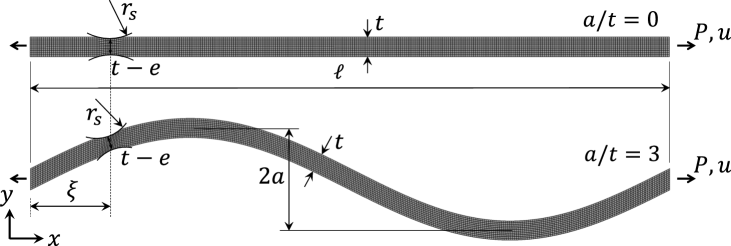
\sidesubfloat[] \sidesubfloat[]
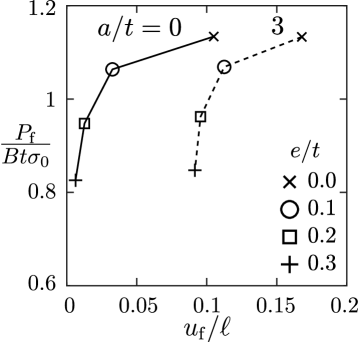
[]
\sidesubfloat[]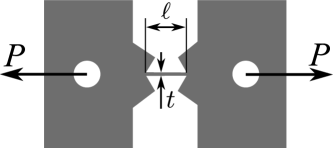 \sidesubfloat[]
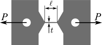
\sidesubfloat[]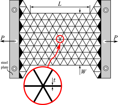
\sidesubfloat[]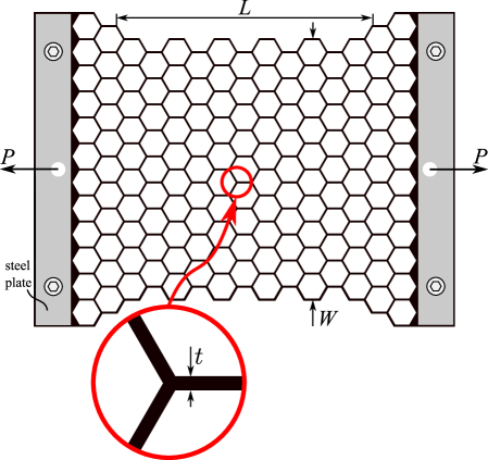


[] \sidesubfloat[]
[]
\sidesubfloat[]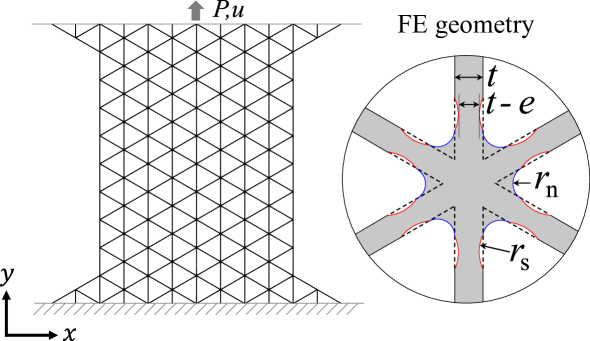
\sidesubfloat[]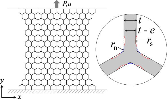
[] \sidesubfloat[]
\sidesubfloat[] \sidesubfloat[]
[]
\sidesubfloat[]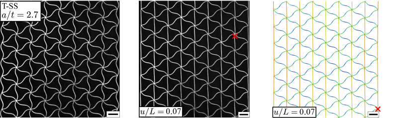
\sidesubfloat[]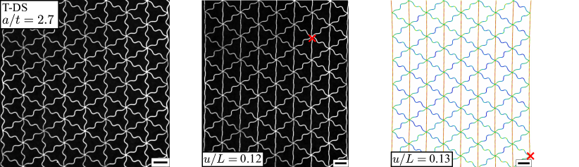
[]
\sidesubfloat[]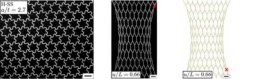
\sidesubfloat[]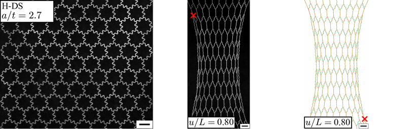
[] \sidesubfloat[]
[] \sidesubfloat[]
\sidesubfloat[] \sidesubfloat[]
[] \sidesubfloat[]
\sidesubfloat[] \sidesubfloat[]