Terraforming the dwarf planet:
Interconnected and growable Ceres megasatellite world
Abstract
We analyse a megasatellite settlement built from Ceres materials in high Ceres orbit. Ceres is selected because it has nitrogen, which is necessary for an earthlike atmosphere. To have artificial gravity, spinning habitats are attached to a disk-shaped megasatellite frame by passively safe magnetic bearings. The habitats are illuminated by concentrated sunlight produced by planar and parabolic mirrors. The motivation is to have a settlement with artificial gravity that allows growth beyond Earth’s living area, while also providing easy intra-settlement travel for the inhabitants and reasonably low population density of 500 /km2. To enable gardens and trees, a 1.5 m thick soil is used. The soil is upgradable to 4 m if more energy is expended in the manufacturing phase. The mass per person is kg, most of which is lightly processed radiation shield and soil. The goal is a long-term sustainable world where all atoms circulate. Because intra-settlement travel can be propellantless, achieving this goal is possible at least in principle. Lifting the materials from Ceres is energetically cheap compared to processing them into habitats, if a space elevator is used. Because Ceres has low gravity and rotates relatively fast, the space elevator is feasible.
keywords:
Ceres , orbital settlementurl]http://www.electric-sailing.fi
Nomenclature
| Cross-sectional area | |
| au | Astronomical unit, 149 597 871 km |
| Energy of burn (Appendix) | |
| Force | |
| Gravitational constant, Nm2/kg2 | |
| Earth’s acceleration of gravity, 9.81 m/s2 | |
| Gravitational field components | |
| Numeric coefficient (Appendix) | |
| Generic angular momentum (Appendix) | |
| Angular momentum due to lifting of mass (Appendix) | |
| Angular momentum of Ceres | |
| Mass of lifted propellant (Appendix) | |
| Mass of lifted payload (Appendix) | |
| Mass of Ceres, kg | |
| Orbit radius, km | |
| Radial distance of tether tip (Appendix) | |
| Radial distance of tip of tether extension (Appendix) | |
| Radius of megasatellite disk | |
| Radius of Ceres, 470 km | |
| Radius of habitat, 1 km | |
| Thruster exhaust speed (Appendix) | |
| Coordinates | |
| Compression | |
| Efficiency of the thruster (Appendix) | |
| Mass density | |
| Ceres angular rotation speed, s-1 | |
| GCR | Galactic cosmic radiation |
| ISRU | In-situ resource utilisation |
1 Introduction
Proposals for extraterrestrial settlements have generally fallen into two categories. On one hand, there are plans to settle the surfaces of Moon and Mars. A fundamental drawback is the low gravity, which raises questions regarding long-term health effects, especially for children whose muscles and bones are growing. Moon and Mars also have smaller surface areas than Earth, so that impact to the financial economy would be limited.
There have also been studies of spinning orbital settlements [1, 2, 3]. They have the benefit of providing healthy artificial gravity. One of their challenges is how to provide travel for goods and people between the free-flying settlements. This issue arises as soon as the population grows larger than what fits in one settlement unit. If the settlements are in heliocentric orbit, they tend to drift apart. This would cause travel times to grow to several months. This problem is avoided if the settlements orbit a common body but then collision avoidance becomes an issue. Lastly, for all orbits it holds that if travel is based on rocket propulsion, the scheme is not long-term sustainable because propellant atoms cannot be recycled. After exiting from the nozzle, a propellant atom starts to orbit the Sun. Sooner or later it is ionised by a solar ultraviolet photon, after which it is accelerated out from the Solar System by the solar wind’s electric field.
In this paper we study the possibility of attaching the spinning habitats to a fixed frame, a megasatellite. Propellantless travel between the habitats is then possible along the megasatellite’s structure. The geometry of the megasatellite is chosen in such a way that the megasatellite is self-similarly growable. The intention is to have only one megasatellite which grows as new settlements are built. The rotary joints between the habitats and the megasatellite do not limit the lifetime or cause reliability issues if one uses passively safe Inductrack-type magnetic bearings with no physical contact [4, 5]. We choose Ceres as the source body to be mined for the materials, because it has nitrogen [6, 7]. Nitrogen is a necessary component of the settlement’s air.
2 How people wish to live
For the settlers to live well, the environment must be sufficiently earthlike:
-
1.
Earthlike radiation shielding.
-
2.
Earthlike atmosphere.
-
3.
artificial gravity.
-
4.
24 h diurnal cycle with 130 W/m2 insolation, like in southern Germany.
-
5.
Nature, fields, parks, forests.
-
6.
Population density 500 /km2, like in the Netherlands.
-
7.
Large, interconnected world.
The environment can also be better than Earth:
-
1.
No adverse weather.
-
2.
No natural disasters. (Concerning new threats, we show in subsection 4.9 below that the meteoroid impact threat can be at least mitigated well or perhaps even eliminated.)
-
3.
Ultimately growable to larger living area than Earth.
The goal is that the artificial world is long-term sustainable. The flux of escaping atoms must be small, and ideally all atoms should circulate. One of the implications is that daily use of in-space rocket propulsion is not acceptable, because propellant atoms escape from the Solar System permanently. Even if an atom is not injected to Solar System escape speed directly, eventually it gets ionised by a solar UV photon, after which it is taken away by the solar wind.
One might ask if a reduced pressure pure oxygen atmosphere would also work. It is known from the Gemini and Apollo programmes that astronauts can live in such atmosphere without problems at least for a few weeks. However, with our present knowledge, long term health impacts to the lungs cannot be excluded. Even at reduced pressure, a pure oxygen atmosphere also increases the risk of fire because there is no inert gas that would contribute to cooling of a flame. Because the mass density of air would be low, it would also make it challenging for insects and birds to fly. Insects are needed for pollination, and people would miss birds if they were not around. Hence we require an earthlike atmosphere with nitrogen.
We formulate the corresponding technical requirements:
-
1.
Radiation shielding of 7600 kg/m2, when made of 20 % of water and 80 % of silicate regolith, is sufficient. We made OLTARIS [8] run with this composition, augmented by 1 kg/m2 of boron-10 to absorb neutrons, for 1987 solar minimum conditions at 1 au, with a spherical configuration which is the worst-case assumption, and obtained 20.45 mSv/year equivalent dose and 5.808 mGy/year absolute dose. According to [9], 20 mSv/year and 6 mGy/year are suitable limits.
-
2.
The quality of artificial gravity is improved when the rotation radius is made larger. Globus and Hall [10] analysed this issue and found that a rotation period of 30 s is a conservative choice and a period of 15 s or even 10 s gives acceptable quality. The question is fundamentally open, however, until crewed orbital experiments with artificial gravity are made. To be reasonably certain that quality of artificial gravity is high, we adopt a rotation radius of 1 km which corresponds to rotation period of 66 s.
-
3.
Per person, there is 2000 m2 of living space, which we divide into rural space (about 1100 m2) and urban space (about 900 m2). The rural space is gravity. For the urban space we allow somewhat lower gravity, such as .
-
4.
To enable trees, we assume 1.5 m soil depth in the rural space. We assume soil density of 1500 kg/m3, then the mass per unit area of the soil is 2250 kg/m2. The rural space is illuminated by natural sunlight, with diurnally averaged insolation of 130 W/m2.
-
5.
The urban space has no soil and it uses artificial illumination.
-
6.
The atmosphere height is 50 m and 15 m for rural and urban space, respectively.
3 Ceres as source body
We choose Ceres as the source body from which the building materials are mined. The primary reason is that Ceres has nitrogen, which is necessary for the settlement’s atmosphere. Alternatively, one might consider a carbonaceous asteroid, but those C-type asteroids that have at least 100 km size and that have reasonably low eccentricities are about equally far from Earth than Ceres. The asteroids are likely to have less nitrogen than Ceres, although accurate data of Ceres and C-type asteroid nitrogen abundance are not available at this point.
We choose to orbit Ceres so that the settlement remains physically close to the source body. This ensures that the material transfer time in the construction phase remains relatively short. We use a high orbit to minimise tidal forces. We adopt km circular equatorial orbit. This is smaller than the Hill’s sphere radius of Ceres (207,000 km), so that the orbit is expected to be long-term stable without maintenance. We have not performed simulations to check this, however, so this issue remains to be studied in the future.
We recommend using a space elevator to lift materials from Ceres. The elevator cable length is 1024 km and the cable strength requirement is straightforward to meet. Lifting from the surface takes only 54 kJ/kg of energy. After elevator, we need 20 m/s of delta-v to circularise the orbit.
Ceres is water-rich, so it would also be possible to make H2/O2 propellant and use rockets to lift the materials. We prefer the space elevator, however, because it needs much less energy per lifted mass.
4 Growing Ceres megasatellite
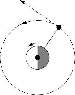
Consider a disk-shaped megasatellite in equatorial Ceres orbit (Fig. 1). A number of spinning habitats are attached to both sides of the disk, denoted by dots. To gather sunlight, two 45o inclined mirrors are added. The megasatellite is in microgravity so the mirrors and their support structures are lightweight. Nearly all mass is in the habitats. Thus the mass distribution can be made circularly symmetric so that the tidal torque is zero. To keep the mass distribution symmetric, one can transfer water or other ballast fluid between tanks. Any remaining tidal torque must be treated by active attitude control, for example by using the spinning habitats as reaction wheels. Small changes in the level of artificial gravity are not likely to be problematic for the inhabitants. A propulsive attitude control system can exist as a backup.
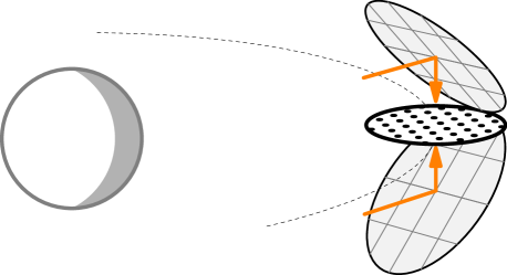
Because the orbit of Ceres has eccentricity, there is libration about the correct Sun-pointing direction in different parts of the orbit. The libration occurs because the orbital angular speed of Ceres varies according to Kepler’s second law, while the megasatellite rotates at a constant rate. One way to deal with the libration would be to keep the megasatellite turned exactly towards the Sun at all times by using large reaction wheels. A more attractive solution is to make the mirrors from tiltable segments that are able to direct sunlight vertically towards the disk even when sunlight arrives a bit from the side. This reduces the amount of gathered light by the cosine of the libration angle but the effect is insignificant because worst-case factor is . The mirror segments can be small and numerous, so the solution can be made redundant and reliable. Thus, reaction wheels are not needed.
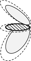
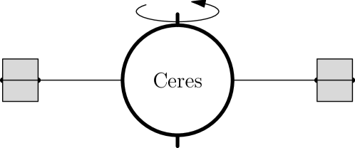
The megasatellite of Fig. 1 is self-similarly growable at the edges. One can extend the megasatellite by growing both the disk and the mirrors as shown in Fig. 2.
4.1 Gathering sunlight
Sunlight is concentrated into a rotating habitat by primary and secondary mirrors, which are cylindrical paraboloids (Fig. 3). The primary mirror’s focal ring coincides with a light entry slit which is an opening in the habitat’s radiation shielding envelope. The opening is shaped such that the habited areas do not have direct unshielded view to space. This is sufficient to block radiation because high-energy radiation propagates straight without bending around corners or appreciably reflecting from surfaces: the straight-ahead approximation is typically valid in shielding studies [11], and the straight-ahead approximation is also made in OLTARIS. The secondary mirror is inside the envelope and it injects light into a light channel which is parallel to the rotation axis.
4.2 Synthetic diurnal cycle
From the light channel, light is tapped to illuminate the rural space through windows. The urban space is located inward of the light channel and is artificially illuminated (Fig. 3b). The urban and rural space are concentric cylinder surfaces. The radius of the rural space is the same as the habitat radius km.
To keep the usage of total incoming sunlight temporally constant, the rural space is divided into three timezones in the vertical direction (Fig. 4a). The timezones are shifted from each other by hours. The total amount of light received by the living space is temporally constant (Fig. 4b). The light channel has an adjustable ceiling made of (more or less diffusely) reflecting material. The slope of the ceiling adjacent to a zone determines the level of sunlight in the zone.
To ensure darkness during simulated night despite some stray light, blinders are used during nighttime. In each zone, the sun rises at 6 am and the light level increases linearly until 10 am (Fig. 4b). The light level stays constant until 2 pm when it starts to decline linearly towards the sunset at 6 pm. The piecewise linear light curve approximates the more ideal sinusoidal dependence rather well (Fig. 4b).
The rural space is 50 m high and 5 km long along the cylinder axis. There is another upside-down cylinder attached to it which makes the total length of the unit 10 km. The attached cylinder receives light from a symmetric light gathering system below.
The light channel is 137 m wide. The width of the light channel is determined by Sun’s angular diameter at Ceres distance.
Adding seasonal variations to the lighting scheme would likely be possible but it is outside the scope of this paper.
4.3 Thermal design
Minimisation of structural mass implies minimisation of rotating mass. Therefore we make the radiation shield non-rotating. The shield must be separated from the habitat by a gap. Figure 5 shows cross-section of the habitat soil and the radiation shield, with temperatures marked. The heat flux 141 W/m2 matches well with the wanted insolation of 130 W/m2 plus some extra heat dissipation due to imperfections in the internal mirrors and dissipation of electric power consumed inside the habitat.
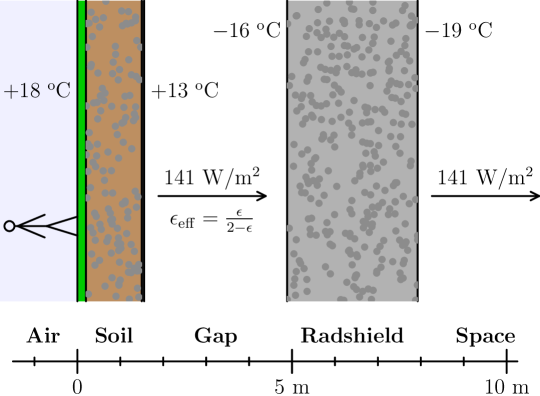
Both the soil and the radiation shield need an internal liquid heat transfer system, because the thermal conductivity alone would be insufficient. In soil, the heat transfer fluid can be water because all parts are above the freezing point. In the radiation shield the liquid must be more cold-tolerant, for example some light hydrocarbon such as heptane. Ceres is rich in carbon and hydrogen for producing hydrocarbons.
We assume +18 oC diurnally averaged habitat temperature. The minimum nighttime temperature is +13 oC and the maximum afternoon temperature is +23 oC. The dewpoint tends to settle close to the nighttime minimum temperature of +13 oC.
For the internal surface adjacent to the vacuum gap, we assume emissivity of 0.95. For the external surface we assume a slightly lower emissivity value of 0.92, because it is exposed to potential modifications caused by space radiation and micrometeoroids.
In the calculation of radiative cooling, we took into account the effect of the inclined mirrors, using a conservative approximation. We also took into account the mutual view factors of the habitat cylinders using a simple ray-tracing calculation for thermal infrared photons.
We made the calculations for Ceres aphelion. For other phases of the orbit, some of the mirror elements are turned to reject light. In this way, the illumination level inside the habitats and the required cooling are constant.
Figure 6 shows 3-D renderings of the megasatellite. The illumination was chosen to help visualisation. We did not use Sun illumination from a realistic direction because it would have made the renderings more challenging to understand.
4.4 Megasatellite frame structural mass
Consider the megasatellite disk of radius in equatorial Ceres orbit with orbital distance km (Fig. 7).
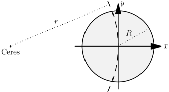
When the coordinate origin is fixed at the centre of the disk, Ceres is at . The gravity field within the disk along the axis is
| (1) |
Let us assume , which is qualitatively valid even for very large megasatellites e.g. and an accurate approximation for smaller sizes. Then
| (2) |
The constant term is cancelled by the orbital centrifugal force so that the effective gravity within the disk along () is
| (3) |
In the same approximation, along the axis the gravity field is
| (4) |
Consider a uniform column of mass of cross-sectional area and mass density within the disk along from to . The tidal compression force at is
| (5) |
The compression is
| (6) |
Consider case which is a very large megasatellite of km for people. If the material is steel with kg/m3, we obtain MPa, which on Earth would correspond to steel column height of
| (7) |
This is quite low structural requirement. If the structural mass fraction is only 0.1 %, for example, then the compression is 150 MPa which is well tolerated by steel. The tidal pull in direction is two times higher.
Overall, the tidal forces increase with the megasatellite radius but the additional structural mass due to them is only % even for very large megasatellite of radius km.
4.5 Mass of magnetic bearings
The mass of the Inductrack magnetic bearings is many orders of magnitude smaller than the total mass so it is negligible in the mass budget. A rough reasoning is that in earthly maglev trains, the magnetic levitation system is able to carry the weight of the train in without overwhelmingly dominating the mass budget. In 100,000 km Ceres orbit, the gravity field of Ceres is and the microgravity in the satellite is smaller than this by factor where is the megasatellite radius and km is the orbital radius. Hence the forces that the bearings have to carry are smaller than on Earth by a factor or more. Thus the mass fraction of the magnetic bearings is expected to be or less.
4.6 Interconnectivity
Fast and easy travel between the habitats is necessary. In order to be long-term sustainable, the travel must also be propellantless. It cannot be based on rocketry.
A straightforward way is that the passenger stations are located at the ends of the rotating habitat cylinders, at the cylinder axes. Passengers use an elevator to get to the axis. They experience weightlessness during the trip, apart from the acceleration and deceleration phases of the vehicle when it moves in a tunnel that connects the habitats. There are many technical options for the vehicles. The vehicles might resemble autonomous cars or they might be more like trains. They might move on wheels along rails or use magnetic levitation. They could move in vacuum or in air. If they move in vacuum, either the vehicles or the passengers must move through airlocks at both ends of the trip.
When first encountered, weightlessness causes nausea and vomiting for some people. However, in a settlement where people experience occasional weightlessness from childhood, it is plausible to think that they can tolerate it well during short trips. Nevertheless, since this not known with certainty, travel solutions where weightlessness can be avoided are worth studying. Gravity can be maintained at the stations if the station is placed at the perimeter of the cylinder. Vehicles move at constant speed, which is the same as the rotation speed at the distance from the centre where the station is. The vehicles do not stop at the station because the station is moving at the same speed as the vehicle. One can have gravity also during the trip if one winds the tunnels into spirals. This mode of transportation can coexist with the baseline zero gravity version explained above, because the stations are located in different areas of the habitat. Having more than one mode of transportation available increases safety by providing redundancy. As a safety feature for abnormal situations, there must also be a docking port for external spacecraft in both ends of each habitat cylinder.
The tunnels probably do not need radiation shielding against GCRs, because people spend only small fraction of their time travelling. Full shielding of the tunnels would increase megasatellite mass by only 2–3 %, though.
4.7 Geometric parameters and mass budget
Table 1 lists the main parameters. The parameters are listed for the twin cylinder that goes through the symmetry plane and comprises also the downward pointing parts seen in Fig. 6a. The two halves of the habitat cylinder are physically connected and enclosed into the same radiation shield.
| Habitat radius | 1 km |
|---|---|
| Habitat length | 10 km |
| Parabolic reflector radius | 4.4 km |
| Population | 56700 |
| Living area | 114 km2, 2000 m2/person, 44.9 % urban |
| Urban gravity | 81 % |
| Electric power | 6.26 kW/person, 7.0 W per urban m2 |
| Rotation period | 1.06 min |
| Power dissipation | 156 kW/person |
| Heat flux | 141 W/m2 |
| Light channel width | 137 m |
| Light channel insolation | 5.0 suns |
The electric power given in Table 1 was reached in the following way. We assumed that all areas not covered by the paraboloid collector (the habitat cylinder roof, a ring around the cylinder, and areas between adjacent paraboloids) are used for solar panels that have 20 % efficiency. Further, we made arbitrary assumption that 50 % of the produced power is used for the habitats while the other half is reserved for megasatellite level functions such as the transportation network and attitude and orbit control.
Table 4.7 gives the mass budget of the megasatellite as computed from the geometric model using parameters of Table 1.
| Item | Mass/person | Fraction |
|---|---|---|
| Shield | 6712 t | 68.7 % |
| Soil and biosphere | 2481 t | 25.4 % |
| Structural | 484 t | 5.0 % |
| Air | 96 t | 1.0 % |
| Total | 9774 t | 100 % |
4.8 Manufacturing energy
The manufacturing energy is dominated by making tensile structural material, which is needed to contain the centrifugal force of artificial gravity and the internal pressure. One option for the structural material is piano wire steel (music wire, ASTM A228 alloy, 0.7–1 % C, 0.2–0.6 % Mn, remainder Fe) whose yield strength is listed by MatWeb as 1590–1760 MPa. In the calculation we have assumed tension of 760 MPa which is a bit less than half of the lowest table value.
In 1998, DeBeer et al. [12] estimated the worldwide average energy consumption for steel making to be 24 MJ/kg, while the most energy-efficient process used 19 MJ/kg and reductions to 12.5 MJ/kg were foreseen, or down to 10 MJ/kg with waste heat recovery techniques. In this paper we adopt the value of 20 MJ/kg for steel and ignore the energy consumption of other than structural materials.
4.9 Impact threat
Impacts are a potential new threat. However, this risk can be effectively mitigated or perhaps even eliminated completely. Collisions of sub-meter scale meteoroids do not penetrate the radiation shield. For large impactors, early detection and evasive manoeuvre of the habitat or deflection of the impactor is feasible. If there remains a class of mid-range impactors that is not covered by these strategies, one can use active near-range defence based on kinetic kill vehicles or/and lasers. Finally, if warning comes too late to apply other defences, one can evacuate people from the threatened end of the cylinder habitat, or if there is sufficient time, from that cylinder altogether.
5 Obtaining the materials
5.1 Space elevator
The Cererian equatorial escape speed is only 426 m/s when launching along rotation. Because Ceres has water, one could electrolyse water and lift material by H2/O2 rockets. However, energetically it is much cheaper to use a space elevator (Fig. 8). The altitude of the stationary orbit is 722 km and the altitude of the tether tip to inject to elliptical orbit reaching 100,000 km altitude is 1024 km. Thus the tether length is 1024 km. For example, if the tether is made of dyneema (ultra-high molecular weight polyethylene fibre, mass density 975 kg/m3) tensioned at 1240 MPa (40 % of the tensile strength of 3.1 GPa), the tether mass is only 23 % of the lifted payload mass. If the lifting speed is 10 m/s, for example, the lifting takes 28 hours. A round cable tether might break due to a meteoroid impact but a non-planar tape tether or tubular tether resists impacts well.
A 5 cm wide and 25 m thin initial dyneema tether weighs 1.25 tonnes. It can lift 5000 kg at one time. If the lifting speed is, for example, 10 m/s, lifting takes 28 hours and the average power consumption is 2.6 kW. Thus, an initial tether which is sufficiently wide that it does not break due to micrometeoroids can be installed by a spacecraft of a few tonnes mass. The initial tether will be later replaced by a thicker one which was manufactured from the lifted materials, and the process is repeated. The lifting capacity grows exponentially because in each step, the new tether is many times thicker than the old one.
After releasing from the tip, the payload enters an elliptic orbit which must be circularised by a 20 m/s apoapsis propulsive burn. For example, with specific impulse of 100 s (steam rocket), the propellant fraction is 2 %. Per mass unit, the energy needed by the elevator is 54 kJ/kg. Making +300 C steam from -130 C Cererian ice requires MJ/kg of heat energy, which multiplied by the propellant fraction yields 80 kJ/kg. Thus, in total the energy needed to lift from surface to 100,000 circular orbit is 54+80=134 kJ/kg. If using a H2/O2 rocket, the energy cost would be times higher.
The number of elevators could be more than one. For example, Figure 9 shows two elevators on opposite sides of Ceres. Their combined area of solar panels produces average power which is equivalent to covering 20 % of Ceres surface by solar panels.
5.2 Surface transportation on Ceres
On the surface of Ceres, the mined material must be transported to the elevator(s). The transportation can use wheeled trucks. The trucks can have large solar panels to generate power. Large panels are feasible because the gravity is only . On Ceres, the night lasts only 4.5 hours. Therefore the vehicles, once they are of sufficient size, can stall during the night and rely on insulation and thermal inertia to maintain sufficient internal temperature. The vehicles do not necessarily need energy storage devices. This is a welcome simplification because the energy storage devices would have to be ISRU.
6 Resource limits
The above analysis can be summarised by the following numbers:
-
1.
Mass per living area 5000 kg/m2, of which 5 % (250 kg/m2) is structural mass (steel) whose production takes 20 MJ/kg of energy.
-
2.
Thus, production energy is 1 MJ/kg. Per living area it is J/m2.
-
3.
Living area 2000 m2/person, thus kg/person and J/person.
-
4.
Megasatellite disk area 1175 m2/person.
6.1 Ceres mass resource
Ceres mass kg kg would suffice for building 200 billion square kilometres of living area, i.e., 400 times larger than Earth’s surface area. At population density of 500 /km2, such area would accommodate people, i.e., times current world population. A megasatellite of this extreme size would reside in a heliocentric orbit, because it would not fit in Ceres orbit.
6.2 Ceres angular momentum resource
Ceres rotation period is 9.07 hours and radius km. The internal mass distribution is not known but let us assume for simplicity that it is uniform. Then the moment of inertia is
| (8) |
and the angular momentum is Nms. At tether tip at 1024 km altitude, the tip speed is 287 m/s so the angular momentum per injected payload mass is Nms/kg. Then each kilogram of launched material reduces Ceres angular momentum by fraction . For example, launching kg of material reduces Ceres angular momentum by 2.7 %. This amount suffices to build km2 of living area for people. The megasatellite’s diameter is 12,000 km, i.e., 12 % of the orbiting distance.
If there is a need to go beyond the angular momentum resource of Ceres, one could extend the elevator tether and compensate for the angular momentum loss by applying propulsion at the extended tip. The energy needed by propulsion is independent of the tether length, while the needed propellant mass decreases if the tether is made longer. The energy needed is a few times larger than with plain space elevator but significantly less than lifting material by H2/O2 rocket propulsion. The details are given in Appendix A below.
The internal structure of Ceres is poorly constrained at the moment. If the structure is such that the crust and the core are separated by a fluid layer, then speculatively it might happen that using the space elevator would cause the crust to slow down relative to the core. If the resulting velocity shear in the fluid layer is concentrated to small regions, those regions might heat up sufficiently to potentially cause cryovolcanism, which would be an undesired side effect. In such case, one might apply the angular momentum restoration strategy mentioned in the above paragraph already earlier. There is no risk that such situation would develop unnoticed, because monitoring the rotational response of the surface to space elevator operation reveals if velocity shear is developing below.
6.3 Speed of lifting material
If one covers 20 % of Ceres area by solar panels, or places an equivalent power production capacity in the space elevator(s) directly (Fig. 9), one produces 4.8 TW of electric power. Lifting material by the elevator takes 54 kJ/kg. One also needs 20 m/s of propulsive delta-v to circularise the orbit, and to produce the propellant also takes energy. Let us assume, however, that the orbit circularisation energy is generated during the 52-days long trip of the payload from the elevator tip to the apoapsis.
We then obtain that one can lift kg/year. This suffices for 280 million new people per year. This is larger than current yearly increase of world population, which is about 80 million per year. A large megasatellite of population and km2 living area takes 360 years to build at this rate.
6.4 Timescale of energy-limited bootstrapping
Let us consider the question in what timescale the infrastructure could be bootstrapped. The space elevator can lift its own mass in only few hours. From the lifted material, a larger power system and thicker tether must be made. Because lifting mass is fast, mass does not limit the growth rate. The limitation comes from how fast the existing power system can generate the amount of energy that is needed to produce the next generation power system from the lifted material. Going from an initial kilowatt level to final terawatt level takes doublings. If the doubling time (the energy payback time) of the power system is, for example, 4 months, then bootstrapping takes 10 years. The fact that Ceres is at larger heliocentric distance does not increase the payback time because it can be compensated by reflecting concentrators. In the Cererian orbit, microgravity conditions prevail. In microgravity, parabolic concentrators are energetically cheap to make because they can be lightweight.
Because the growth is not mass-limited, the elevator can produce mass for bootstrapping of the megasatellite, simultaneously with bootstrapping itself. First one builds the megasatellite with frame, parabolic concentrators and solar panels, but without the habitats and radiation shields. This is done to scale up the power production capacity as quickly as possible. When the power production capacity is ready, one starts to produce structural material for the habitats, which takes the majority of the energy. Per living area, J/m2 is needed, while the insolation on living area is 130/2=65 W/m2 (rural insolation 130 W/m2 divided by 2 because living area includes also the urban space which is roughly 50 %). Assuming 20 % solar panel efficiency, we thus produce = 13 W/m2 of power. Dividing J/m2 by 13 W/m2 yields 12 years timescale for making the rest of the habitat, once the power system is ready.
6.5 Overall bootstrapping timescale
In summary, if a power system’s doubling time (payback time) is 4 months, bootstrapping the elevator and the power system of the megasatellite takes 10 years. Then, using the megasatellite’s power system, it takes another 12 years to build the habitats and the radiation shields, with total time of 22 years. In addition, the area of solar panels that fits in Ceres stationary orbit limits the building speed to 280 million new people per year, if panel area equivalent to 20 % of Ceres surface is used as illustrated in Fig. 9.
Our bootstrapping analysis concerned only the physical limits of mass, energy and angular momentum. Physics allows bootstrapping in only 22 years under the stated assumptions. It is likely, of course, that the actual bootstrapping timescale would be longer, or much longer, and instead of physics, it would be driven by technological delays and the logistics of transporting the inhabitants from Earth.
7 Discussion
Interestingly, cooling is a more important design driver than solar power. For example, cooling restricts the number of concentric rural spaces to one. If the heliocentric distance would be smaller, the habitat cylinders would be closer together since the paraboloid mirrors would be smaller. This would increase the mutual view factors between the habitats and thereby reduce cooling. It seems that Ceres is just at the right heliocentric distance to make the symmetric two-sided mirror architecture feasible without having to reject sunlight.
Our cooling system uses also liquid heat transfer, but only over a few metres across the soil and the radiation shield. Then the liquid heat transfer system can consist of many small loops so that if a pipe breaks for any reason, the amount of fluid released is small.
There is a tradeoff between soil thickness and the energy cost of manufacturing. The default soil thickness of 1.5 m can be increased up to 4 m, at the cost of refining more of the Ceres raw material into tensile structural material such as steel or dyneema. The total mass would not change, only the energy expended in processing the raw material of Ceres soil would be linearly higher.
The goal is to be able to use Ceres material in sequential order without sorting out any of it. The goal seems feasible, because the radiation shields and soil are the largest mass components and their composition is flexible. The radiation shields and soil are effectively our trash bin. The iron mass fraction of Ceres is 13–17 % [13, Fig. 7] so there is enough raw material for structural steel. The only thing that might spoil this plan is if Ceres turns out to have less than % of nitrogen. In that case, mining of nitrogen might be necessary from deep subsoil fluids of Ceres, for example, or one would have to reduce the 50+15 m atmospheric height.
The megasatellite is growable from one to millions of habitats. The megasatellite is grown simply by building new habitats at the edges and expanding the mirrors correspondingly (Fig. 2). As the megasatellite grows, at some point one has to add some structural reinforcement also to existing portions of the megasatellite, but mass-wise the additions are minor. Also the traffic system may have to be upgraded because growth of the world increases the amount of through traffic.
The utility value of the megasatellite becomes apparent if we compare it with traditional surface settlements. It would be technically possible to colonise the surface of Ceres by centrifuge habitats. However, then the magnetic bearings would have to carry the weight of the habitat. The weight is 34 times less than on Earth but many orders of magnitude more than in the megasatellite’s microgravity conditions. Another challenge would be solar illumination. Because Ceres rotates, the solar concentrator mirrors would have to track the Sun, and the 9-hour diurnal cycle does not suit people’s natural daily rhythm. To avoid these issues, probably the habitats would be artificially illuminated. The small size of Ceres would limit the available solar power, which would limit the population to few hundred million. Even if there would be a non-solar energy source, the surface area of Ceres would limit the total power. The megasatellite’s area can grow much larger than Ceres. Because the Sun shines without interruptions and always from the same direction, it is feasible to use sunlight directly for illumination. This is aesthetically pleasing and energetically efficient.
The megasatellite has two superficial drawbacks relative to surface settlements. One is that one must build the megasatellite frame and the mirrors. However, their mass fraction is 1 per cent or less. The other drawback is that materials must be lifted to orbit, but this is not significant because the lifting takes only 134 kJ/kg of energy. This is much less than the 1 MJ/kg needed to process them. The processing energy is dominated by the tensile structures needed to create artificial gravity and pressure containment, which are needed in surface dwellings as well. Furthermore, it is cheaper to obtain the energy in high orbit where there is no eclipsing and the Sun shines from a constant direction so that parabolic concentrators become simple. The concentrators are also lightweight because structurally they need to withstand only microgravity, not Ceres gravity.
The scale (radius, length) of the habitats is a free parameter. If the habitats are made larger, the manufacturing energy increases roughly linearly with radius, because one needs more structural material to withstand the centrifugal force. The total mass does not change. Also, nothing prohibits having habitats of different size in the same megasatellite.
The overall level of difficulty of executing this project is probably similar to settling Mars. The delta-v and triptime to Ceres are longer, but on the other hand one avoids planetary landings and the atmospheric weather and dust. On Ceres it requires some effort to lift the materials to orbit using the elevator, but it is energetically cheap. Once the materials are in high Ceres orbit, the thermal environment is uniform and energy is easy to get due to absence of eclipses.
8 Conclusions
We have analysed a megasatellite settlement that provides gravity, interconnectivity, growability to beyond current world population, 2000 m2 living area per person, thick soil to enable a natural environment with trees, along with optimal weather and absence of natural disasters. The settlement is built in Ceres orbit by lifting Ceres materials by a space elevator. The mass per person is kg and the manufacturing energy per person is J. The mass is dominated by radiation shields and soil. The manufacturing energy is dominated by tensile structural material such as steel needed to withstand the centrifugal force of artificial gravity and the pressure containment.
We select Ceres as the source body because it is more likely than C-type asteroids to have sufficient nitrogen. Nitrogen is a critical element because it is needed for the settlement atmospheres. We use a disk geometry for the megasatellite because its symmetry eliminates tidal torque so that reaction wheels are not needed to maintain attitude. The habitats are illuminated by natural sunlight. The sunlight is gathered onto the disk by two planar mirrors inclined at angle and concentrated to desired intensity by parabolic mirrors.
Future work should involve analysis of the exponential bootstrapping phase and transportation of people from Earth to Ceres. Also, different technical alternatives for the travel system between the habitats should be looked into. Orbit simulations are needed to find what is the highest altitude of a long-term stable orbit around Ceres.
Acknowledgements
The results presented have been achieved under the framework of the Finnish Centre of Excellence in Research of Sustainable Space (Academy of Finland grant number 312356). The author thanks Kadri Bussov for discussions that led to changing the geometry and Sini Merikallio and Al Globus for commenting the manuscript.
Appendix A Preventing angular momentum loss by propulsion
Nomenclature of the Appendix
| Energy of burn | |
| Numeric coefficient | |
| Generic angular momentum | |
| Angular momentum due to lifting of mass | |
| Mass of lifted propellant | |
| Mass of lifted payload | |
| Orbit radius, km | |
| Radial distance of tether tip | |
| Radial distance of tip of tether extension | |
| Radius of Ceres, 470 km | |
| Thruster exhaust speed | |
| Efficiency of the thruster | |
| Ceres angular rotation speed, s-1 |
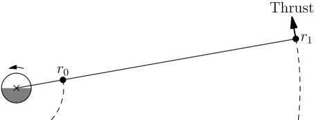
Consider some payload mass lifted from Ceres surface to the elevator tip at radial distance km from Ceres’ centre, Fig. 1. The tether length 1024 km is sufficient to inject objects to elliptic orbit whose apoapsis is at km distance. The angular momentum loss of Ceres is
| (9) |
Assume that there is an extension of the tether up to some larger distance . We apply propulsion at to try and cancel the angular momentum loss. The propellant mass is transferred from Ceres along the tether. After lifting it to , its angular momentum has increased by . This angular momentum was also taken from Ceres, so overall the propulsive burn must create angular momentum . The exhaust speed of the thruster (i.e., specific impulse in velocity units) must be at least . Let us write where . The produced angular momentum is . Equating it with and solving for yields
| (10) |
The energy consumed by the burn is
| (11) |
where is the efficiency of the thruster. Let us select, for example, . Typically , and using this approximation we obtain
| (12) |
which is independent of . For example, if km and thrust efficiency , then km/s, and kJ/kg, which is 5.6 times larger than the energy needed to lift mass to the normal elevator tip . In principle one could get back part of this energy because lifting to liberates rather than consumes energy.
In summary, it is possible to prevent Ceres angular momentum loss by using propulsion at tip of elevator tether extension. The energy expended in making the propellant is nearly independent of the tether length. The propellant mass is reduced if one makes the tether longer. The specific impulse is proportional to the tether length, although there is some freedom. Chemical hydrogen-oxygen thruster is among the possibilities. It implies 10,000 km tether length and % of the lifted mass being water which is electrolysed and consumed as propellant. The energy and propellant mass consumed by this scheme is less than lifting the material from the surface by direct chemical propusion.
References
- O’Neill [1974] G.K. O’Neill, “The colonization of space”, Physics Today, 27, 9, pp. 32–40 1974. https://space.nss.org/the-colonization-of-space-gerard-k-o-neill-physics-today-1974/
- O’Neill [1977] G.K. O’Neill, “The high frontier”, New York, 1977.
- Arora et al. [2012] N. Arora, A. Bajoria and A. Globus, “Kalpana One: Analysis and design of space colony”, 47th AIAA/ASME/ASCE/AHS/ASC Structures, Structural Dynamics, and Materials Conference, 1–4 May, 2006, Newport, Rhode Island. https://arc.aiaa.org/doi/abs/10.2514/6.2006-2183
- Post and Ryutov [2000a] R.F. Post and D.D. Ryutov, “The Inductrack: a simpler approach to magnetic levitation”, IEEE Transactions on Applied Superconductivity, 10, 1, pp. 901–904, 2000.
- Post and Ryutov [2000b] R.F. Post and D.D. Ryutov, “The Inductrack approach to magnetic levitation”, 16th Int. Conf. on Magnetically Levitated Systems and Linear Drives, Rio de Janeiro (BR), 06/06/2000–06/11/2000.
- King et al. [1992] T.V.V. King, R.N. Clark, W.M. Calvin, D.M. Sherman and R.H. Brown, “Evidence for ammonium-bearing minerals on Ceres”, Science, 255, 5051, pp. 1551–1553, 1992.
- DeSanctis et al. [2015] M.C. De Sanctis, E. Ammannito, A. Raponi, S. Marchi, T.B. McCord, H.Y. McSween, F. Capaccioni, M.T. Capria, F.G. Carrozzo, M. Ciarniello, A. Longobardo, F. Tosi, S. Fonte, M. Formisano, A. Frigeri, M. Giardino, G. Magni, E. Palomba, D. Turrini, F. Zambon, J.-P. Combe, W. Feldman, R. Jaumann, L.A. McFadden, C.M. Pieters, T. Prettyman, M. Toplis, C.A. Raymond and C.T. Russell, “Ammoniated phyllosilicates with a likely outer Solar System origin on (1) Ceres”, Nature, 528, pp. 241–244, 2015.
- Singleterry et al. [2011] R.C. Singleterry, Jr., S.R. Blattnig, M.S. Clowdsley, G.D. Qualls, C.A. Sandridge, L.C. Simonsen, T.C. Slaba, S.A. Walker, F.F. Badavi, J.L. Spangler, A.R. Aumann, E. Neal Zapp, R.D. Rutledge, K.T. Lee, R.B. Norman and J.W. Norbury, “OLTARIS: on-line tool for the assessment of radiation in space”, Acta Astronautica, 68, pp. 1086–1097, 2011.
- Globus and Strout [2017] A. Globus and J. Strout, “Orbital space settlement radiation shielding”, NSS Space Settlement J., 2017. https://space.nss.org/media/NSS-JOURNAL-Space-Settlement-Radiation-Shielding.pdf
- Globus and Hall [2017] A. Globus and T. Hall, “Space settlement population rotation tolerance”, NSS Space Settlement J., 2017. https://space.nss.org/media/NSS-JOURNAL-Space-Settlement-Population-Rotation-Tolerance.pdf
- Alsmiller et al. [1968] R.G. Alsmiller, Jr., D.C. Irving and H.S. Moran, “The validity of the straightahead approximation in space-vehicle shielding studies – part II”, Nucl. Sci. Eng., 32, pp. 56–61, 1968.
- DeBeer et al. [1998] J. De Beer, E. Worrell and K. Blok, “Future technologies for energy-efficient iron and steel making”, Ann. Rev. Energy Environment, 23, pp. 123–205, 1998.
- Prettyman et al. [2019] T.H. Prettyman, N. Yamashita, E. Ammannito, B.L. Ehlmann, H.Y. McSween, D.W. Mittlefehldt, S. Marchi, N. Schörghofer, M.J. Toplis, J.-Y. Li, C.M. Pieters, J.C. Castillo-Rogez, C.A. Raymond and C.T. Russell, “Elemental composition and mineralogy of Vesta and Ceres: distribution and origins of hydrogen-bearing species”, Icarus, 318, pp. 42–55, 2019.