Degeneracy of cross sections in scattering of light
Abstract
We theoretically and numerically prove that under an electromagnetic plane wave with linear polarization incident normally to cylindrical passive scatterers, a single energy diagram can integrate absorption, scattering, and extinction cross sections for arbitrary scattering systems, irrespective of internal configuration, material parameters, and its sizes. For a system with definite resonant orders, along the corresponding boundary of the energy diagram, not only the magnitudes of scattering coefficients, but also its phases, are required the same, corresponding to superabsorption or superscattering. For systems composed by larger resonant orders, the domain of the energy diagram can completely cover systems with lower one. Hence, systems with different resonant orders can provide the same energy characteristics, reflecting the energy degenerate property in light scattering. This degeneracy may relax more degrees of freedom in functional designs, such as energy harvesting, imaging, sensing devices. We demonstrate various systems based on real materials to support this finding.
pacs:
Understanding of the limitation of interaction between scatterers and electromagnetic radiation is of importance for a variety of applications, such as solar energy harvesting energy1 ; energy2 ; energy3 , strengthening the interaction of light and subwavelength objects enhance1 , bio-imaging imaging1 ; imaging2 , highly directivity of antennas super1 ; kerker1 ; kerker2 , sensing sensor , and medical heating treatment at nanoscales heating1 ; heating2 ; heating3 .
Scattering and absorption of light by an extremely subwavelength scatterer with an isotropic and homogeneous structure can not go beyond a single resonant order book1 ; single1 ; single2 . To overcome this limit, a composite subwavelength system by proper multi-layered configurations can induce multiple resonances. It has been demonstrated that, in the whispering gallery condition, excitation of a confined polariton can lead to a system with a degenerate resonant super-scattering superscattering1 ; superscattering2 ; superscattering3 . Analogous to degenerate resonant mechanism, superabsorber, that not only can retain minimum scattering power but also can arbitrarily strengthen absorption, was demonstrated, superabsorber .
We note that due to passive materials embedded, physical energy conservation law must be met, that is often overlooked but important. By this physical law, the corresponding partial absorption, scattering, and extinction cross sections are definitely bounded, irrespective of inherent system configurations, material parameters, and operating environment phase1 ; phase2 . Consequently, as a benefit of the obtained phase diagram for scattering coefficients, we can find that for each resonant order, scatterer systems can support a variety of energy absorption with constant scattering power. However, when encountering multiple resonant orders interference, the answer to whether there can have an energy diagram to indicate arbitrary scattering configurations is far from obvious and remains open. The answer can definitely provide global information in light scattering and also understand the inherent limits, with potential applications in the development of nano-photonics devices.
Inspired by the concept from the calculus of variations landau , in this work, we borrow differential calculus as well as the employed Lagrange multiplier to address energy distribution for scattering of light. We theoretically and numerically prove that under an electromagnetic plane wave with linear polarization excitation, for a cylindrical system, there exists one energy diagram where can integrate all possible scattering configurations. The energy diagram can reveal an one-to-one correspondence for absorption, scattering, and extinction cross sections. But, on the contrary, there has no such one-to-one relation for scattering coefficients, reflecting the degenerate property in light scattering. For a system with definite resonant orders, along the corresponding domain boundary, the magnitudes of scattering coefficients and its phase are required, which corresponds to superabsorption or superscattering. In addition, we observe that for the scattering system with lower scattering orders, its domain is just the subspace of higher ones. Therefore, one can design a scatterer system, through exciting high orders, to simulate the identical energy performance occurred at low orders. We demonstrate quasi-superscattering and quasi-superabsorption to support this finding. We believe our results can provide more degrees of freedom for nano-photonics designs in energy harvesting, imaging, sensing.
Consider a cylindrically symmetric scatterer is normally impinged by a plane wave with electric field oscillated along the z-axis direction, i.e., s mode. The scattering, extinction, and absorption powers can be expressed in the following book1 ; superscattering1 ; linear ,
| (1) |
where is amplitude of incident electric field, is complex scattering coefficient, is environmental wave number, and and are free space permittivity and permeability note . Without loss of generality we set . We note that due to cylindrical symmetry, the scattering coefficients have a symmetry for . For , they correspond to electric dipole, magnetic dipole, and magnetic quadrupole, respectively. The extinction power, summation of absorption and scattering power, is also related to the optical theorem, which links the scattering electric field at the forward direction optical ; optical1 ; optical2 ; optical3 . Thus, systems with non-zeros of energy dissipation and radiation, they must possess a non-zero electric field along the forward direction. The promotion of absorption, under constant extinction, would reduce the scattering, that would further lower the scattering intensity over all direction, but it still remains the constant for scattering electric field in the forward direction. Now, due to passive material embedded, the partial absorption cross sections for each orders would be restricted , because of energy conservation. Here is defined as normalized partial absorption power. Following this inequality, we obtain a clear physical bound on the scattering coefficients for orders, i.e., and kerker1 ; phase1 .
For each order, the normalized partial absorption power can not go beyond , while the upper limit for normalized partial scattering power, defined as , is . Therefore, if a system has a orders excited, the maximum absorption power can not be larger than while the corresponding scattering power would be , corresponding coherent perfect absorption absorption . In an extreme situation, the maximum scattering power in orders can reach , while its corresponding absorption is zero. Then, it is naturally extended to seek for the existence of the energy diagram when more complicated resonance orders excited.
To address such a fundamental problem, we use the differential calculus as well as the Lagrange multiplier to figure out the energy diagram under given dissipated power math ; landau . Suppose our system has a fixed dissipation power , we expect to evaluate the extreme scattering power . Now, is a constraint with primary to involved, i.e.,
| (2) |
Here we have no assumption for the scattering coefficients.
Then, we define a energy function L related to scattering and absorption powers as follows
| (3) |
where is a Lagrange multiplier, and we have used the phasor representation for complex scattering coefficients, here is the argument of .
To have the extreme minimum or maximum of the scattering powers, the energy function L is required to meet,
| (4) |
which are valid for to . In the latter expression, to obtain non-trivial solutions for and , we obtain or . However, by energy conservation, the only applicable solution would be . By this outcome, the first expression in Eq.(4) would be
| (5) |
Thus, we have Further, , that the magnitudes of scattering coefficients are identical and the corresponding phases are , for each orders.
Consequently, we can express the scattering coefficients in terms of absorption power,
| (6) |
that there are two extrinsic scattering performances under given absorption.
In the square root, it can guarantee the real value, because for N orders dominant. The ultimate limit would be maxima absorption, i.e., , corresponding to coherent perfect absorption absorption . More appealingly, our results imply that under constant absorption power, there can support two solutions for scattering powers:
| (7) |
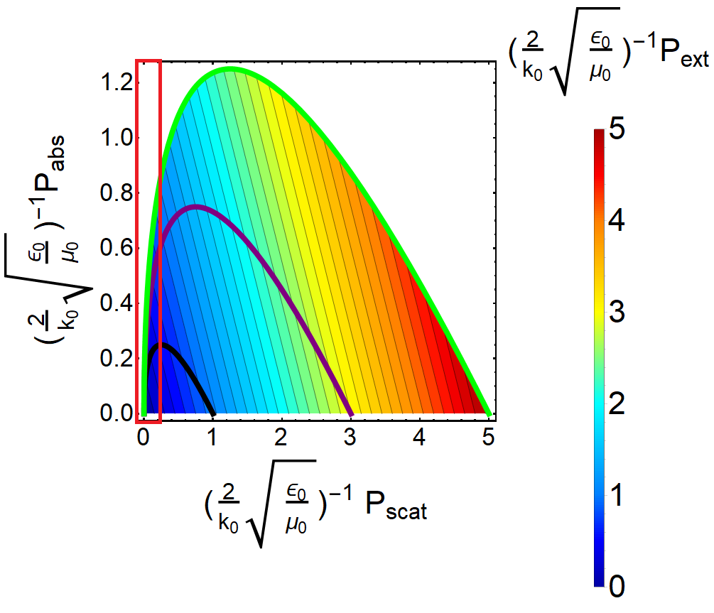
Now, we depict an energy diagram involving normalized scattering, absorption, and extinction cross sections as shown in Fig. 1 note2 . The boundary of the energy diagram is followed by where for resonance orders dominant. We construct the density plot for normalized extinction power, defined as , in Fig. 1. It clearly reveals the limit of normalized absorption, scattering, and extinction powers. Here represents a system with only electric dipole resonance supported, has electric and magnetic dipoles resonances, while a system with consists of electric, magnetic dipoles, and magnetic quadrupole resonances. The maximum normalized extinction power accompanies with the maxima of normalized scattering power, while the corresponding normalized absorption is zero. Additionally, with the constant normalized extinction power, the increasing normalized absorption (dissipation) can reduce the output scattering performance. We note that by considering optical theorem, this constant normalized extinction would require the fixed cost in forward electric field, but it could have a reduction in scattering distribution over all direction when absorption involved. Interestingly, within the regime of lower scattering, as indicated by red line box in Fig. 1, the energy diagram reflects the existence of a higher absorption power when multiple resonant orders are properly involved, corresponding to a superabsorption superabsorber . We will discuss this interesting scattering property in the following. Moreover, although for N resonant orders, it has a definite domain boundary, the corresponding domain is just a subspace of a higher orders system, which implies that the scattering states are degenerate in energy cross sections.
As a result, the scattering system can display the same energy performance, but its inherent constitution is completely different. We emphasize that only the boundary for the corresponding resonant system requires a definite constraint in scattering coefficients, but there have no such one-to-one correspondences for that inside the domain.
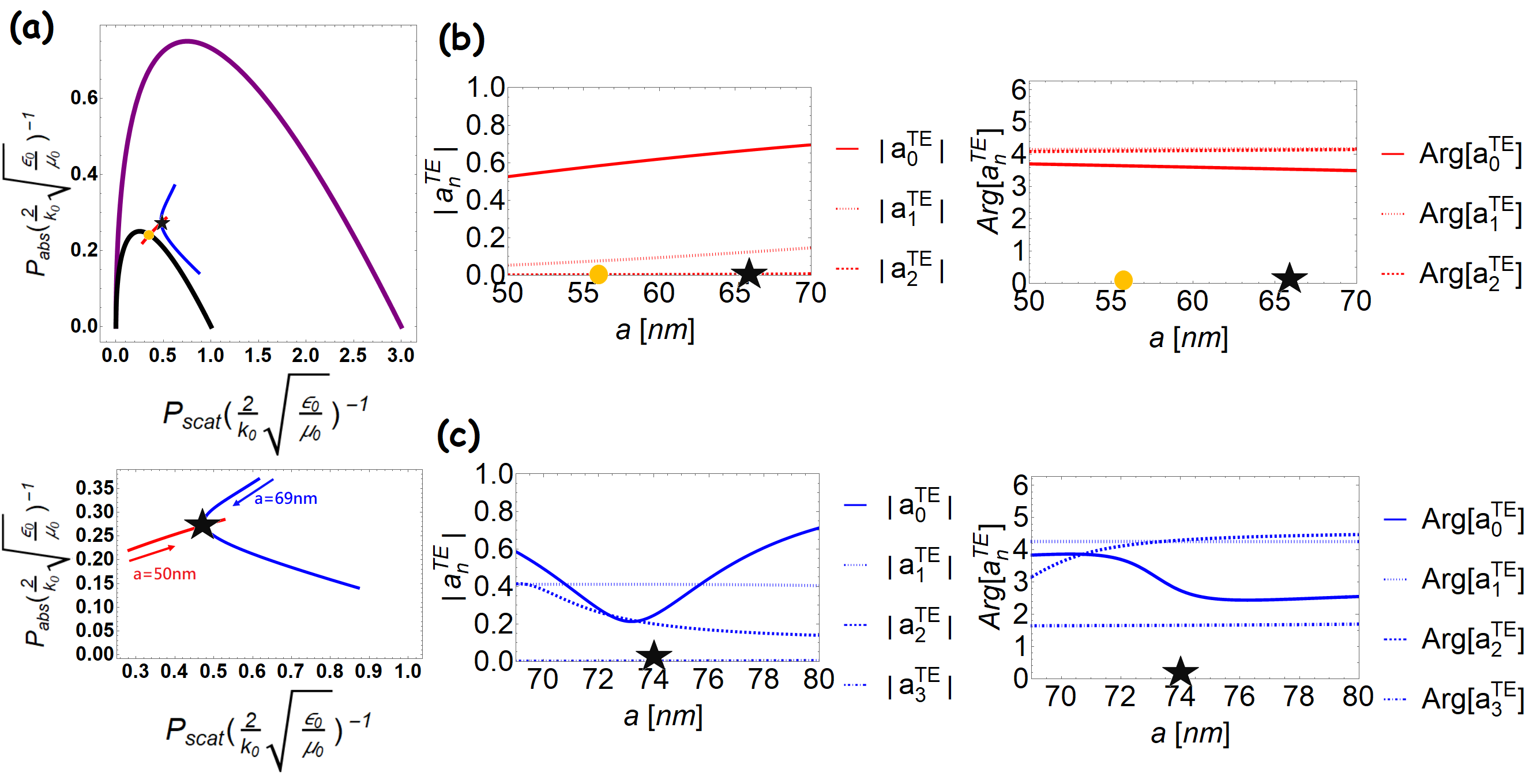
To verify our finding, in Fig. 2, we first discuss the systems with realistic materials embedded handbook . We choose two systems with different geometrical sizes, materials, and inherent configurations, but at the same operating wavelength nm. In Fig. 2 (a), the result by a red line represents that a core-shell nanowire system is constituted by golden in shell and silicon in core, while the blue line is from a homogeneous silicon nanowire. We tune the outer radius from nm to nm for the core-shell system, while the ratio of shell-core radii is fixed constant . For the homogeneous silicon nanowire, we tune the radius from nm to nm. Initially, the rad line residues in region when the outer radius is nm, its energy distribution then goes through region when the outer radius is larger than nm marked by a yellow point in Fig. 2 (a). In order to understand its underlying mechanism, we investigate the magnitudes and phases of the scattering coefficients for each orders in Fig. 2 (b). We can observe that the dominant order is by at nm, however, with the increasing geometrical size, the order would gradually become another primary contribution. We also find that the phase from the primarily contributed order is nearly when close to the boundary with , as expected.
For the system made by only silicon, we depict a blue line for a relation between the normalized absorption and scattering powers by geometry size from nm to nm in Fig. 2 (a). We can see, in Fig. 2 (c), that the contributed orders are , which obviously belong to scattering space . This outcome implies that the domain should be , but its location also crosses over , which reflects the subspace of high orders. Moreover, with radius being nm, we find the whole powers including absorption, scattering, and extinction, are identical to that of the core-shell system at outer radius being nm, which marked by a black star symbol. Although their constitution of scattering components is totally different, they can provide the same energy distributions, reflecting the energy degeneracy in scattering of light.
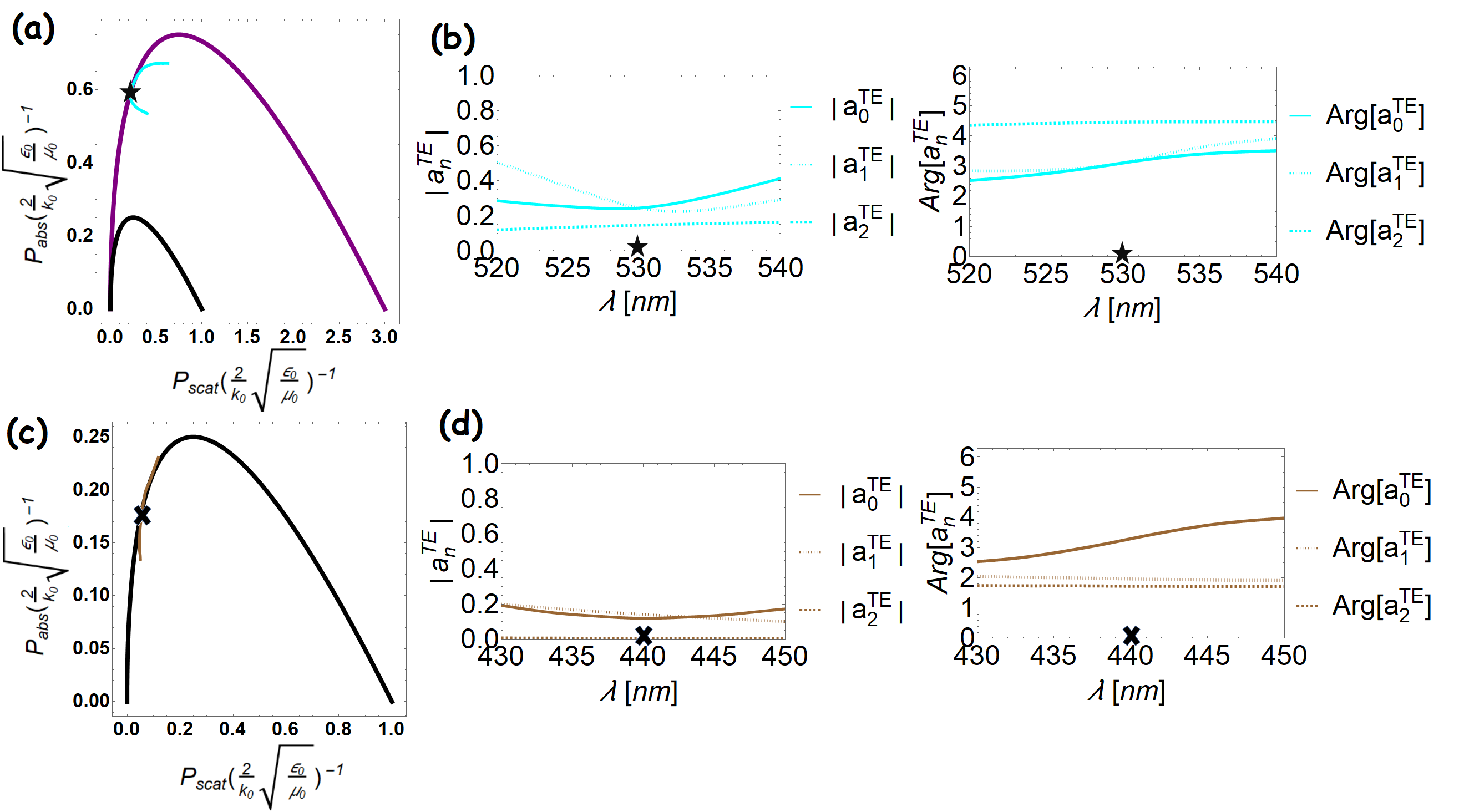
Now, we turn to discuss the existence of the superabsorption, in which the system can absorb more energy by increasing resonant order numbers while maintaining lower scattering power, as highlights in red box of Fig. 1 superabsorber . We consider a core-shell nanowire system made by silicon in shell and gold in core, where the ratio of inner to outer radius is fixed to and the outer radius is chosen as nm. The material dispersions we consider here are all based on experiments, handbook . In Fig. 3 (a), we study energy distribution of the core-shell system with respect to varying operation wavelength from nm to nm, as denoted by cyan color line. To understand its inherent scattering components, we also plot the scattering coefficients for each orders from , as shown in Fig. 3 (b). In this wavelength range, the dominant orders are . We note that only at nm, the cyan line would intersect with the boundary marked by a black star, revealing a system with lower scattering but larger absorption. Here the normalized absorption and normalized scattering power are , respectively. From the right side of Fig. 3 (b), it is interesting to see that the phases from dominant orders at nm would be , satisfying the superabsorption requirement.
Furthermore, we consider another system configuration by silicon in shell and silver in core with an outer radius of nm and the ratio of inner to outer radii being . Fig. 3 (c) shows a brown color trajectory within the wavelength of nm to nm. Here the system obviously resides in domain. We mark an operating nm by a black cross, corresponding to an intersection at boundary, with lower scattering as well as larger absorption. The normalized absorption and normalized scattering power in this case are , respectively. However, when analyzing the components of the scattering coefficients in Fig. 3 (d), we find the primary orders to be and . As for its phase analysis in Fig. 3 (d), the phases of primary orders are not needed to be . We note that this system certainly possesses the desirable energy distribution to superabsoption, but its scattering coefficients have not met in the work superabsorber , because this system belongs to the high scattering space domain. This outcome reveals that when designing a subwavelengthly system associated with energy issue, it can have an opportunity to relax the constraints on inherent scattering states when considering a system with high scattering domain.
In the superscattering case, the systems can have multiple partial wave resonances occurred at same wavelength, beyond single order limit. In appendix A, we consider an alternative system to support the similar result, but without the need of phase matching on scattering. Before conclusion, we want to remark that although our discussion is limited to cylindrical systems, but there has a similar result to a spherical system where supports a degenerate energy characteristic. The finding of the general energy diagram, irrespective of inherent system configurations, material choices and operating wavelength, would provide complete information in designing functional energy systems. Last but not least, our demonstration of quasi-superabsorption and quasi-superscattering systems, without relying on resonant mechanism, would allow the system with larger quality factor.
In conclusion, with the approach of differential calculus as well as the use of Lagrange multiplier, we develop the general energy digram involving scattering, absorption, and extinction, for any passive systems. We observe that at the boundary of energy diagram of the scatterer system, it requires scattering coefficients the same for each orders. However, inside the diagram, there has no such correspondence to scattering coefficients. When a system consists of higher resonant orders, the corresponding diagram can completely cover a system with lower ones. This result reflects a energy degenerate property in light scattering. As a result, system could have the same energy performance, but could possess different scattering states intrinsically. We discuss systems with quasi-superabsorption and quasi-superscattering, but without the phase-matching constraints. This work not only provides the complete information for energy distribution in the process of light scattering, but also highlights degrees of freedom in practical designs.
I Acknowledgement
The author thanks Professor Ray-Kuang Lee for helpful discussions. This work was supported by Ministry of Science and Technology, Taiwan (MOST) (--M- - -MY3).
References
- (1) L. Cao, P. Fan, A. Vasudev, J. White, Z. Yu, W. Cai, J. Schuller, S. Fan, and M. Brongersma, “Semiconductor Nanowire Optical Antenna Solar Absorbers,” Nano Lett. 2, 439–445 (2010).
- (2) E. C. Garnett, M. L. Brongersma, Y. Cui, and M. D. McGehee, “Nanowire solar cells,” Annu. Rev. Mater. Res. 41, 269–295 (2011).
- (3) M. L. Brongersma, Y. Cui1 and S. Fan, “Light management for photovoltaics using high-index nanostructures,” Nat. Mater. 13, 451 (2014).
- (4) K. Kneipp, Y. Wang, H. Kneipp, L. T. Perelman, I. Itzkan, R. R. Dasari, and M. S. Feld,“Single Molecule Detection Using Surface-Enhanced Raman Scattering (SERS),” Phys. Rev. Lett. 78, 1667 (1997).
- (5) A. P. Slobozhanyuk, A. N. Poddubny, A. J. E. Raaijmakers, C. A. T. van den Berg, A. V. Kozachenko, I. A. Dubrovina, I. V. Melchakova, and Y. S. P. A. Belov, “Enhancement of magnetic resonance imaging with metasurfaces,” Adv. Mater. 28, 1832 (2016).
- (6) C. Rizza, E. Palange, M. Alecci, and A. Galante “Mimicking Localized Surface Plasmons via Mie Resonances to Enhance Magnetic-Resonance-Imaging Applications,” Phys. Rev. Applied 14, 034040 (2020).
- (7) S. Arslanagić and R. W. Ziolkowski, “Highly Subwavelength, Superdirective Cylindrical Nanoantenna,” Phys. Rev. Lett. 120, 237401 (2018).
- (8) J. Y. Lee, A. E. Miroshnichenko, and R.-K. Lee, “Reexamination of Kerker’s conditions by means of the phase diagram,” Phys. Rev. A 96, 043846 (2017).
- (9) J. Y. Lee, A. E. Miroshnichenko, and R.-K. Lee, “Simultaneously nearly zero forward and nearly zero backward scattering objects,” Opt. Express 26, 30393 (2018).
- (10) A. Alú and N. Engheta, “Cloaking a Sensor,” Phys. Rev. Lett. 102, 233901 (2009).
- (11) X. Huang, P. K. Jain, I. H. El-Sayed, and M. A. El-Sayed, “Plasmonic photothermal therapy (PPTT) using gold nanoparticles,” Lasers Med. Sci. 23, 217 (2008).
- (12) M. I. Tribelsky, A. E. Miroshnichenko, Y. S. Kivshar, B. S. Lukyanchuk, and A. R. Khokhlov, “Laser pulse heating of spherical metal particles,” Phys. Rev. X 1, 021024 (2011).
- (13) L. R. Hirsch, R. J. Staord, J. A. Bankson, S. R. Sershen, B. Rivera, R. E. Price, J. D. Hazle, N. J. Halas, and J. L. West, “Nanoshell-mediated near-infrared thermal therapy of tumors under magnetic resonance guidance,” Proc. Natl. Acad. Sci. U.S.A. 100, 13549 (2003).
- (14) C. F. Bohren and D. R. Huffman, Absorption and Scattering of Light by Small Particles (Wiley 1983).
- (15) R. E. Hamam, A. Karalis, J. D. Joannopoulos, and M. Soljačić, “Coupled-mode theory for general free-space resonant scattering of waves,” Phys. Rev. A 75, 053801 (2007).
- (16) M. I. Tribelsky and B. S. Luk’yanchuk, “Anomalous Light Scattering by Small Particles,” Phys. Rev. Lett. 97, 263902 (2006).
- (17) Z. Ruan and S.-H. Fan, “Superscattering of Light from Subwavelength Nanostructures,” Phys. Rev. Lett. 105, 013901 (2010).
- (18) C. Qian, X. Lin, Y. Yang, X. Xiong, H. Wang, E. Li, I. Kaminer, B. Zhang, and H. Chen, “Experimental Observation of Superscattering,” Phys. Rev. Lett. 122, 063901 (2019).
- (19) Z. Ruan and S.-H. Fan, “Design of subwavelength superscattering nanospheres,” Appl. Rev. Lett. 98, 043101 (2011).
- (20) N. M. Estakhri and Alú, “Minimum-scattering superabsorbers,” Phys. Rev. Lett. 89, 121416(R) (2014).
- (21) J. Y. Lee and R.-K. Lee, “Phase diagram for passive electromagnetic scatterers,” Opt. Express 24, 6480 (2016).
- (22) A. E. Miroshnichenko and M. I. Tribelsky, “Ultimate Absorption in Light Scattering by a Finite Obstacle,” Phys. Rev. Lett. 120, 033902 (2018).
- (23) L. D. Landau and E. M. Lifshitz Course of Theoretical Physics vol 1 Mechanics 3rd edn (Oxford: Butterworth-Heinemann).
- (24) We note that most theoretical studies concentrate on resonant systems in p mode, i.e., TM, magnetic field is along z axis superscattering1 ; superscattering3 . Here we show that such multiple resonant results in subwavelength dimension could be found in s mode. On the other hand, by duality, the related TM formulas could be obtained by replacing , , , and .
- (25) J. Y. Lee, Y.-H. Chung, A. E. Miroshnichenko, and R.- K. Lee, “Linear control of light scattering with multiple coherent waves excitation,” Opt. Lett. 44, 5310 (2019).
- (26) R. G. Newton, “Optical theorem and beyond,” Am. J. Phys. 44, 639 (1976).
- (27) J. D. Jackson, Classical Electrodynamics (Wiley, New York, 1975).
- (28) A. Alú and N. Engheta, “How does zero forward-scattering in magnetodielectric nanoparticles comply with the optical theorem?” J. Nanophoton. 4, 041590 (2010).
- (29) W. Liu and Y. S. Kivshar, “Generalized Kerker effects in nanophotonics and meta-optics,” Opt. Express 26, 13085 (2018).
- (30) H. Noh, Y.-D. Chong, A. D. Stone, and H. Cao,“Perfect coupling of light to surface plasmons by coherent absorption” Phys. Rev. Lett. 108, 186805 (2012).
- (31) F. B. Hildebrand, Methods of applied mathematics (Dover 1992).
- (32) Cross section is defined by power over intensity of incident wave and its unit is wavelength. Thus, the power we used here is the multiplication of the cross section with incident intensity.
- (33) E. D. Palik, Handbook of Optical Constants of Solids (Academic Press, New York, 1985).