Present address: ]Laboratory for Solid State Physics, ETH Zürich, 8093 Zürich, Switzerland
Magnetic order in the chemically-substituted frustrated antiferromagnet CsCrF4
Abstract
The effect of chemical substitution on the ground state of the geometrically frustrated antiferromagnet CsCrF4 has been investigated through a neutron powder diffraction experiment. Magnetic Fe-substituted CsCr0.94Fe0.06F4 and nonmagnetic Al-substituted CsCr0.98Al0.02F4 samples are measured, and magnetic Bragg peaks are clearly observed in both samples. Magnetic structure analysis revealed a 120∘ structure having a magnetic propagation vector in CsCr0.94Fe0.06F4. For CsCr0.98Al0.02F4, a quasi-120∘ structure having is formed. It is notable that the identified magnetic structure in CsCr0.94Fe0.06F4 belongs to a different phase of ground states from those in CsCr0.98Al0.02F4 and the parent CsCrF4. These results suggest that the Fe substitution strongly influences the ground state of CsCrF4.
I Introduction
Geometrically frustrated magnets have attracted great interest in condensed matter physics because of their exotic magnetic states induced by macroscopic degeneracy of magnetic states at low temperatures Balents2010 ; Savary2017 . Since the macroscopic degeneracy in the low-energy region can be lifted even by small perturbations, geometrical frustration highlights small effects such as single-ion anisotropy Moessner1998 ; Melchy2009 , the Dzyaloshinskii-Moriya interaction Elhajal2002 ; Elhajal2005 , magnetic dipole-dipole interaction Hertog2000 ; Maksymenko2015 , exchange randomness Saunders2007 ; Andreanov2010 ; Watanabe2014 ; Kawamura2014 , and site dilution Garcia2001 ; Maryasin2013 ; Andreanov2015 . These may play key roles in determining ground states in frustrated magnets.
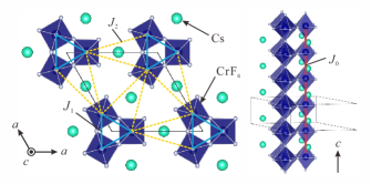
The equilateral triangular spin tube antiferromagnet CsCrF4 is one of the intriguing species in geometrically frustrated magnets Manaka2009 ; Manaka2011_1 . It crystallizes in a hexagonal structure with the space group as illustrated in Fig. 1. The magnetic properties are due to Cr3+ ions. It is unique that equilateral triangles formed by CrF6 octahedra are stacked along the crystallographic axis, forming triangular spin tubes. These tubes magnetically couple with one another and form the kagome-triangular lattice in the plane Ishikawa2014 ; Seki2015 . Magnetic susceptibility measurements revealed the Curie-Weiss temperature K and a broad maximum at K indicative of developing short-range antiferromagnetic spin correlations Manaka2009 ; Manaka2011_1 . Due to the geometrical frustration and low dimensionality of the triangular spin tube, no clear evidence of a magnetic phase transition was found in thermodynamic and magnetic measurements Manaka2009 ; Manaka2011_1 ; Manaka2011_2 ; Manaka2013 ; Manaka2015 .
In a breakthrough, recent neutron powder diffraction study identified long-range magnetic order of CsCrF4 below 2.8 K. The magnetic moments form a quasi-120∘ structure in the plane Hagihala2018 . The 120∘ structure propagates antiferromagnetically along the and axes with a magnetic propagation vector . Discussion of ground states in the kagome-triangular lattice model suggested that the identified 120∘ structure originates from a ferromagnetic intertube coupling, the Dzyaloshinskii-Moriya interaction, and a strong in-plane single-ion anisotropy. In addition, it was found that the ground state of CsCrF4 is close to the boundary on the magnetic phase diagram in the kagome-triangular lattice model Hagihala2018 . This suggests that small perturbations may induce various types of magnetic states in CsCrF4.
Chemical substitution controls the magnetic state in CsCrF4 Miura2011 ; Manaka2019 . Thermodynamic and magnetic measurements for chemically substituted CsCr1-xFexF4 and CsCr1-xAlxF4 showed that the magnetic state is significantly influenced by the chemical composition Manaka2019 . An antiferromagnetic transition was clearly observed at 4.5 K for in the magnetic Fe-substituted compound, and the substituted superexchange bond Cr3+-F--Fe3+ enhanced the in-plane magnetic anisotropy. A glasslike transition appeared at about 5 K for the nonmagnetic Al-substituted compound. In the present paper, we investigate long-range magnetic ordering in chemically substituted frustrated antiferromagnet CsCrF4. Magnetic structures of CsCr0.94Fe0.06F4 and CsCr0.98Al0.02F4 are identified by a combination of neutron powder diffraction experiments and magnetic structure analysis. The most notable result is that the Fe-substitution effectively turns the ferromagnetic intertube coupling antiferromagnetic.
II Experimental details
Polycrystalline samples of CsCr0.94Fe0.06F4 and CsCr0.98Al0.02F4 were prepared by a solid-state reaction method Manaka2009 ; Manaka2019 . The powder samples were loaded in vanadium-made containers, which were in turn installed in a conventional liquid 4He cryostat. Neutron diffraction measurements were performed at the high resolution powder diffractometer ECHIDNA Echidna2006 ; Echidna2018 installed at the OPAL research reactor operated by the Australian Nuclear Science and Technology Organisation (ANSTO). We chose a Ge(331) monochromator to obtain neutrons with a wavelength of 2.4395 Å, and used the open-open- configuration. Temperatures were set at 10 K and 1.5 K. The neutron diffraction data were analyzed by the Rietveld method with the FULLPROF software PhysicaB192 . Candidates for magnetic structures compatible with the lattice symmetry were obtained by the SARA software PhysicaB276 . We used the VESTA software vesta for drawing the crystal structures and magnetic structures.
III Results and analysis
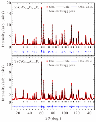
Figures 2(a) and 2(b) show neutron powder diffraction profiles at 10 K for CsCr0.94Fe0.06F4 and CsCr0.98Al0.02F4, respectively. These are reasonably fitted by the hexagonal structure with the space group . Obtained profile factors are % and % for CsCr0.94Fe0.06F4, and % and % for CsCr0.98Al0.02F4. The refined lattice and structural parameters (Table 1) are consistent with the previous results measured by x-ray powder diffraction experiments Miura2011 ; Manaka2019 . We conclude that the crystal structures are retained at low temperatures.
| CsCr0.94Fe0.06F4 | |
|---|---|
| (Å) | 9.56402(7) |
| (Å) | 3.85832(3) |
| Cs () | (0.57202(12), 0, 1/2) |
| Cr and Fe () | (0.22456(23), 0, 0) |
| F () | (0.83226(14), 0, 0) |
| F () | (0.22024(15), 0, 1/2) |
| F () | (0.43914(10), 0.16142(11), 0) |
| CsCr0.98Al0.02F4 | |
| (Å) | 9.56886(6) |
| (Å) | 3.85059(3) |
| Cs () | (0.57203(17) 0, 1/2) |
| Cr and Al () | (0.22327(36), 0, 0) |
| F () | (0.83208(19), 0, 0) |
| F () | (0.22089(21), 0, 1/2) |
| F () | (0.43801(13), 0.16032(15), 0) |
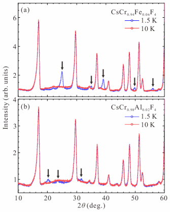
Figure 3 shows neutron diffraction profiles at 1.5 and 10 K, which are below and above the transition temperature observed in the magnetic susceptibility data Manaka2019 . In both samples, diffuse scattering is observed at K in the range of , and it is suppressed below the transition temperature. This behavior is the same as in CsCrF4 Hagihala2018 and indicates that the short-range spin correlations develop at 10 K. For CsCr0.94Fe0.06F4, we clearly see additional peaks at 1.5 K, indicating the long-range magnetic order. Additional peaks are also visible in CsCr0.98Al0.02F4 even though their intensities are weak. This result suggests that the anomaly observed at 5 K in the magnetic susceptibility measurements Manaka2019 corresponds to weak long-range magnetic ordering rather than the glasslike transition. Remarkably, the peaks for CsCr0.94Fe0.06F4 are observed at different scattering angles from those in CsCrF4, while the peak positions in CsCr0.98Al0.02F4 are the same with CsCrF4. Indexing the observed magnetic Bragg peaks results in the magnetic propagation vectors for CsCr0.94Fe0.06F4 and for CsCr0.98Al0.02F4.
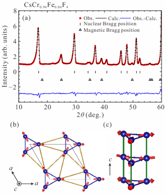
To determine magnetic structures that are compatible with the space group symmetry, we performed representation analysis. We assume that a magnetic structure is described by a single irreducible-representation (IR). For CsCr0.94Fe0.06F4, the representation analysis with the space group and the propagation vector leads to five IRs. The details of the IRs and corresponding basis vectors are listed in Table 2. From the Rietveld refinement, a magnetic structure described by gives excellent agreement with the experimental data, as shown in Fig. 4(a). factors for the whole profile are % and %. The magnetic factor is %. Note that small peaks at and 58∘ are likely due to nonmagnetic impurities because they are also observed at 10 K. In the identified magnetic structure, the magnetic moments form a 120∘ structure in the plane, and they propagate antiferromagnetically along the axis, as displayed in Figs. 4(b) and 4(c). The averaged magnitude of the magnetic moment is evaluated to be 1.66(1) . Since an effective magnetic moment for CrFe is provided by , the refined moment size is much smaller than the effective one. This is the same result as that in the parent CsCrF4 Hagihala2018 . This implies that the magnetic moment strongly fluctuates even at 1.5 K due to the geometrical frustration and low dimensionality.
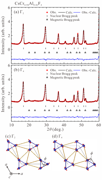
For CsCr0.98Al0.02F4, the representation analysis with the space group and the propagation vector leads to splitting of the three equivalent Cr sites into the two nonequivalent Cr sites; site-1 , , and site-2 . Four and three IRs are associated with the site-1 and site-2, respectively. The details of the IRs and corresponding basis vectors are listed in Table 3. From the Rietveld refinement, magnetic structures in and give satisfactory agreement with the experimental data, as shown in Figs. 5(a) and 5(b). factors for the whole profile are % and % for , and % and % for . Magnetic factors are % for and % for . Note that it is hard to judge the optimal structure from these results because of the weak intensities of the magnetic Bragg peaks. The identified magnetic structures with are similar to that in the parent CsCrF4, [see Figs. 5(c) and 5(d)]. A quasi-120∘ structure is formed in the plane, and it propagates antiferromagnetically along the and axes. Relative angles between the moments at the sites 1 and 2, as indicated in Figs. 5(c) and 5(d), are 92.4∘ for and 90.4∘ for . These angles deviate more from 120∘ than and in CsCrF4 Hagihala2018 . Refined magnitude of the magnetic moments is 1.04(7) for and 1.14(6) for , As well as that of CrFe, the refined moment size of CsCr0.98Al0.02F4 is much smaller than the effective moment for CrAl. Thus, the ordered moments are strongly suppressed by the geometrical frustration and low dimensionality in the chemically substituted CsCrF4.
IV Discussion
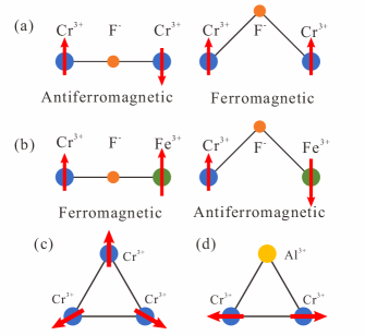
In the magnetic structure analysis, the 120∘ structure having is found for CsCr0.94Fe0.06F4. In the identified structure, the intertube spin configuration is different from that in the parent CsCrF4, but the intratube structure is the same. Let us discuss Fe-substitution effect on exchange interactions. According to the Goodenough-Kanamori rules Goodenough1955 ; Kanamori1959 , superexchange interactions between the Cr3+ ions via the F- ion are antiferromagnetic for a 180∘ bond and ferromagnetic for a 90∘ bond as displayed in Fig. 6(a). Once the Cr3+ ion is substituted by the Fe3+ ion, the superexchange interactions in the 180∘ and 90∘ bonds are turned into ferromagnetic and antiferromagnetic ones, respectively [Fig. 6(b)]. Since the bond angles of the nearest-neighbor exchange paths along the axis, , and in the plane, , (see Fig. 1) are 178∘ and 148∘ in CsCrF4 Hagihala2018 , their exchange interactions likely turn antiferromagnetic into ferromagnetic by the Fe-substitution. However, the identified magnetic structure in the triangular tube retains the same structure as that in CsCrF4. This means that the bond substitution in the intratube coupling has no real effect other than to create a small number of ferromagnetically coupled pairs.
On the contrary, the spin configuration between the spin tubes is totally different from that in CsCrF4. In CsCr0.94Fe0.06F4, the magnetic propagation vector in the kagome-triangular plane is . It contrasts with in CsCrF4. This indicates that the substitution drastically changes the ground state even though intertube exchange paths are complicated. In fact, according to the phase diagram of magnetic structures for the kagome-triangular lattice model Hagihala2018 ; Seki2015 , 120∘ structures having and require antiferromagnetic and ferromagnetic intertube couplings, respectively. We note that in the phase diagram the variation of the in-plane anisotropy described in Ref. Manaka2019 does not change the intertube spin configuration. Therefore, we conclude that in the magnetic Fe substitution the ground state is modified due to the evolution of the intertube coupling from ferromagnetic to antiferromagnetic.
The magnetic structure in CsCr0.98Al0.02F4 is not changed drastically, even though the relative angle between the spins deviates more from 120∘ than that in the parent CsCrF4. On the basis of the classical vector-spin model, spins with the antiferromagnetic interaction form a 120∘ structure on an equilateral triangle, as displayed in Fig. 6(c). Substituting the Cr3+ ion by the Al3+ ion creates a spin vacancy in the triangle. This likely induces the remaining two spins to align antiferromagnetically [Fig. 6(d)]. Consequently, the Al substitution breaks a 120∘ structure locally. However, the spin vacancy only produces a small effect on the ground state of CsCrF4, and therefore the quasi-120∘ structure is still realized globally in CsCr0.98Al0.02F4.
V Conclusion
In conclusion, we have studied magnetic orders in magnetic Fe- and nonmagnetic Al-substituted CsCrF4 through a neutron powder diffraction experiment. Magnetic structure analysis reveals that the Fe-substituted sample exhibits a 120∘ structure having , and the Al-substituted one has a quasi-120∘ structure having . Importantly, the magnetic structure in CsCr0.94Fe0.06F4 differs from that in the parent CsCrF4. This result suggests that the ground state in CsCrF4 is more sensitive to magnetic rather than nonmagnetic substitution on the Cr site. Further studies of magnetic excitation for the Fe-substituted CsCrF4 would be important to elucidate the spin interactions.
Acknowledgments
We acknowledge the support of the Australian Centre for Neutron Scattering, Australian Nuclear Science and Technology Organisation, in providing the neutron research facilities used in this work. The neutron diffraction experiments performed using ECHIDNA at ANSTO, Australia were supported by the General User Program for Neutron Scattering Experiments, Institute for Solid State Physics, The University of Tokyo (Proposals No. 18520), at JRR-3, Japan Atomic Energy Agency, Tokai, Japan. S.H. was supported by the Japan Society for the Promotion of Science through the Leading Graduate Schools (MERIT).
| IRs | Basis Vectors [ ] | |||
|---|---|---|---|---|
| Cr1 | Cr2 | Cr3 | ||
| [1 0 0] | [0 1 0] | [-1 -1 0] | ||
| [0 0 1] | [0 0 1] | [0 0 1] | ||
| [1 2 0] | [-2 -1 0] | [1 -1 0] | ||
| [0 0 2] | [0 0 -1] | [0 0 -1] | ||
| [0 0 0] | [0 0 -] | [0 0 ] | ||
| [2 0 0] | [0 -1 0] | [1 1 0] | ||
| [0 1 0] | [ 0] | [- 0 0] | ||
| +[ 0] | +[ 0 0] | |||
| [0 0 0] | [0 - 0] | [- - 0] | ||
| [ 0] | [- 0 0] | [0 1 0] | ||
| +[- - 0] | +[- 0 0] | |||
| IRs | Basis Vectors [ ] | ||
|---|---|---|---|
| Cr1 | Cr2 | ||
| [0 0 1] | [0 0 1] | ||
| [1 0 0] | [1 1 0] | ||
| [0 1 0] | [0 -1 0] | ||
| [0 0 1] | [0 0 -1] | ||
| [1 0 0] | [-1 -1 0] | ||
| [0 1 0] | [0 1 0] | ||
| Cr3 | |||
| [0 -1 0] | |||
| [0 0 2] | |||
| [2 1 0] | |||
References
- (1) L. Balents, Nature (London) 464, 199 (2010).
- (2) L. Savary and L. Balents, Rep. Prog. Phys. 80, 016502 (2017).
- (3) R. Moessner, Phys. Rev. B 57, R5587(R) (1998).
- (4) P.-É. Melchy and M. E. Zhitomirsky, Phys. Rev. B 80, 064411 (2009).
- (5) M. Elhajal, B. Canals, and C. Lacroix, Phys. Rev. B 66, 014422 (2002).
- (6) M. Elhajal, B. Canals, R. Sunyer, and C. Lacroix, Phys. Rev. B 71, 094420 (2005).
- (7) B. C. den Hertog and M. J. P. Gingras, Phys. Rev. Lett. 84, 3430 (2000).
- (8) M. Maksymenko, V. R. Chandra, and R. Moessner, Phys. Rev. B 91, 184407 (2015).
- (9) T. E. Saunders and J. T. Chalker, Phys. Rev. Lett. 98, 157201 (2007).
- (10) A. Andreanov, J. T. Chalker, T. E. Saunders, and D. Sherrington, Phys. Rev. B 81, 014406 (2010).
- (11) K. Watanabe, H. Kawamura, H. Nakano, and T. Sakai, J. Phys. Soc. Jpn. 83, 034714 (2014).
- (12) H. Kawamura, K. Watanabe, and T. Shimokawa, J. Phys. Soc. Jpn. 83, 103704 (2014).
- (13) A. J. Garcia-Adeva and D. L. Huber, Phys. Rev. B 64, 172403 (2001).
- (14) V. S. Maryasin and M. E. Zhitomirsky, Phys. Rev. Lett. 111, 247201 (2013).
- (15) A. Andreanov and P. A. McClarty, Phys. Rev. B 91, 064401 (2015).
- (16) H. Manaka, Y. Hirai, Y. Hachigo, M. Mitsunaga, M. Ito, and N. Terada, J. Phys. Soc. Jpn. 78, 093701 (2009).
- (17) H. Manaka, T. Etoh, Y. Honda, N. Iwashiwa, K. Ogata, N. Terada, T. Hisamatsu, M. Ito, Y. Narumi, A. Kondo, K. Kindo, and Y. Miura, J. Phys. Soc. Jpn. 80, 084714 (2011).
- (18) H. Ishikawa, T. Okubo, Y. Okamoto, and Z. Hiroi, J. Phys. Soc. Jpn. 83, 043703 (2014).
- (19) K. Seki and K. Okunishi, Phys. Rev. B 91, 224403 (2015).
- (20) H. Manaka and Y. Miura, J. Phys.: Conf. Ser. 320, 012043 (2011).
- (21) H. Manaka and Y. Miura, J. Korean Phys. Soc. 62, 2032 (2013).
- (22) H. Manaka, M. Hagihala, S. Hayashida, M. Soda, T. Masuda, and Y. Miura, Phys. Procedia, 75, 718 (2015).
- (23) M. Hagihala, S. Hayashida, M. Avdeev, H. Manaka, H. Kikuchi, and T. Masuda, npj Quantum Mater. 4, 14 (2019).
- (24) Y. Miura and H. Manaka, J. Phys.: Conf. Ser. 320, 012044 (2011).
- (25) H. Manaka, H. Morita, T. Akasaka, Y. Miura, M. Hagihala, S. Hayashida, M. Soda, and T. Masuda, J. Phys. Soc. Jpn. 88, 114703 (2019).
- (26) K.-D. Liss, B. Hunter, M. Hagen, T. Noakes, and S. Kennedy, Physica B 385-386, 1010 (2006).
- (27) M. Avdeev and J. R. Hester, J. Appl. Cryst. 51, 1597 (2018).
- (28) J. Rodriguez-Carvajal, Physica B 192, 55 (1993).
- (29) A. Wills, Physica B 276-278, 680 (2000).
- (30) K. Momma and F. Izumi, J. Appl. Crystallogr. 44, 1272 (2011).
- (31) J. B. Goodenough, Phys. Rev. 100, 564 (1955).
- (32) J. Kanamori, J. Phys. Chem. Solids 10, 87 (1959).