Electrochemical double layer capacitor using a microemulsion electrolyte
Abstract
The use of aqueous electrolytes in energy storage devices is traditionally limited by the voltage stability window of water at 1.23 V. We present the use of a microemulsion based electrolyte which, although mostly water by mass, has a voltage stability window of up to 5 V. This allows the cost and safety benefits of aqueous electrolytes to finally be realised in high-voltage systems. Supercapacitors constructed using this electrolyte were able to achieve and maintain a capacitance of 40 F/g and an energy density 40 Wh/kg of with a Coulombic efficiency of 99% for over 10,000 cycles on activated carbon.
Keywords Supercapacitor Microemulsion Electrochemical window
1 Introduction
In the diverse energy storage landscape, supercapacitors offer the advantage of fast charge and discharge making them ideal for high power applications such as accelerating vehicles or voltage stabilisation [1]. The current standard electrolyte used in supercapacitors consists of an organic solvent (such as acetonitrile or propylene carbonate) and a quaternary ammonium salt. This combination has good electrochemical stability but is costly as well as potentially hazardous [2]. Using a water-based electrolyte is an attractive option, however, above a potential of 1.23V it is thermodynamically favourable for water to split into oxygen and hydrogen gasses. This means that under most circumstances aqueous supercapacitors are limited to around 1V at maximum. Traditional supercapacitors achieve voltages of between 2.7-3V, above which it is the electrode material (activated carbon) that begins to degrade rather than the electrolyte [3]. Here we present the first use of a microemulsion electrolyte, with water as the major component, in a supercapacitor with which we can achieve 2.7V. By breaking the 1.23V barrier while remaining cheap and sustainable, we anticipate this electrolyte to have significant impact on aqueous electrochemical energy storage technologies and their eventual commercialisation.
Many attempts have been made to extend the electrochemical window of water so that it may be used in high energy density applications such as mobile phone batteries. Recently water-in-salt electrolytes have become popular [4, 5, 6, 7] but other strategies also exist such as choosing materials with high over-potentials for the water splitting reactions [8, 9] or altering the mass balance of the two electrodes [10, 11, 12]. Microemulsions have been used to perform electrochemistry in the past [13, 14, 15, 16], however they have never been pursued in supercapacitors. Microemulsions are thermodynamically stable mixtures of two immiscible solvents, usually water and an ‘oil’, where oil is used to refer to any sufficiently hydrophobic liquid. A surfactant and sometimes a cosurfactant are included to allow for the formation of the microemulsion.
2 Results and Discussion
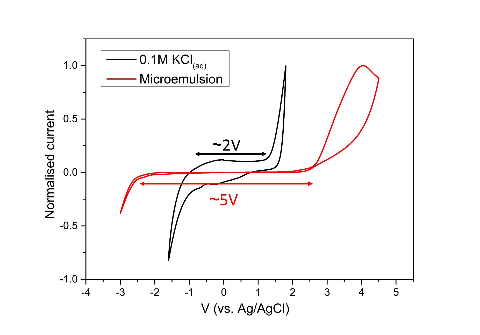
Figure 1 shows a cyclic voltammogram of an aqueous solution of 0.1M KCl and a microemulsion electrolyte with 84 wt% distilled water, 4 wt% Sodium dodecyl sulfate (SDS), 9 wt% n-butanol and 3 wt% cyclohexane. This was recorded at 100 mV/s on a glassy carbon electrode surface.
It was observed that the electrochemical window of the microemulsion is approximately 5 V compared to the 2 V of the KCl solution (Figure 1). The KCl solution showed a window wider than 1.23 V because the water splitting reactions are not favoured on a glassy carbon surface, which causes a high overpotential. This is consistent with other reports of supercapacitors using neutral aqueous solutions being able to achieve 1.6 V [17, 18].
Following this discovery, different solutions were studied on different working electrode surfaces, in order to establish the role of the components of the microemulsion. Solutions of 0.1M aqueous KCl, a surfactant free microemulsion consisting of 26 wt% dichloromethane, 36.5 wt% ethanol and 37.5 wt% water with 0.1M KCl, a solution of 4.9 wt% SDS and the SDS based microemulsion described previously were all tested on a glassy carbon electrode (as a hydrophobic surface) and on a platinum electrode (as a hydrophilic surface).
On the platinum surface (Figure SI 1), the electrochemical windows of all solvents are similar with only slight variation between them. This indicates that in order to observe the extended electrochemical window, a hydrophobic surface must be used.
However, on the glassy carbon surface (Figure SI 2), there is a distinct difference between the solutions. Both the surfactant free microemulsion and the 0.1M KCl solution have similar onset potentials for both oxidation and reduction. The solution with just SDS shows a slightly extended electrochemical window compared to just water which agrees with previous results [19]. However, the microemulsion which has both the surfactant and the oil phase is able shows a significantly larger electrochemical window on both the oxidative and reductive scans.
Therefore, this large extension of the window can be attributed to the formation of an electrode electrolyte interphase (EEI) on the hydrophobic glassy carbon surface (Figure 2).
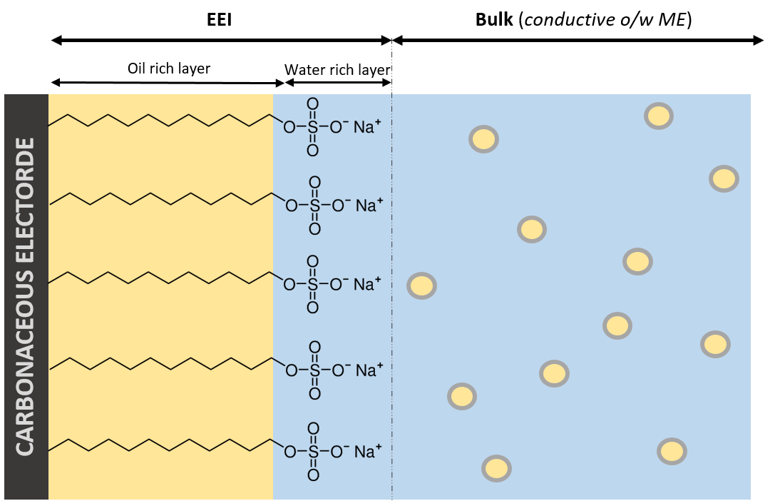
It has been observed previously that the hydrophobic tail of the surfactant arranges itself on the hydrophobic electrode surface [13]. In this surfactant layer the oil phase is concentrated due to interactions between the non-polar tail of the surfactant and the non-polar oil phase. This is followed by a water rich layer around the polar head group of the surfactant molecules. Due to this oil rich layer, little to no water comes into contact with the electrode surface and so water splitting is effectively suppressed and the voltage window over which the voltage is stable is much wider.
In order to utilise this extended electrochemical window and to test the ability of the microemulsion electrolyte to function in an energy storage device, it was used in an electrochemical double layer capacitor (EDLC).
For the supercapacitor electrolyte, sodium chloride (NaCl) was added to the above base microemulsion to achieve a concentration of 0.1 mol/kg. Given that a hydrophobic electrode surface is required activated carbon was chosen as the electrode material over other popular alternatives such as Ruthenium oxides[20] or zeolites [21]. All cells were prepared in ambient conditions on a benchtop without degassing of the electrolytes prior to the construction of the device. Cells containing an aqueous NaCl electrolyte (0.1 M) and cells containing an aqueous solution that was 4.9 wt% SDS were also constructed and tested with galvanostatic charge discharge experiments to test their voltage stability (Figure SI 3).
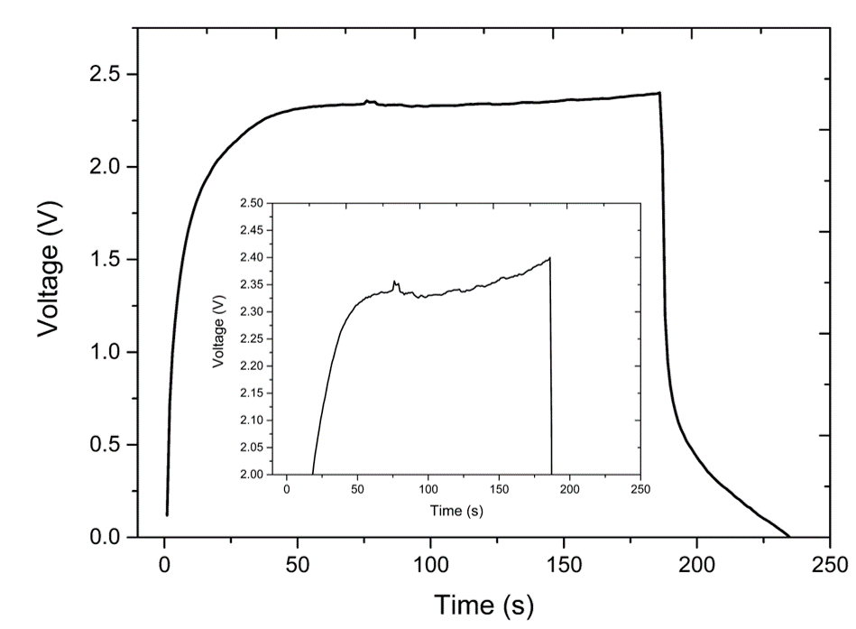
Cyclic voltammetry was used to investigate the electrochemical window of the cell. Figure 3a shows the cut-off voltage being raised sequentially. From this it can be determined that the maximum voltage of these supercapacitors is approximately 2.7V
Using electrochemical impedance spectroscopy (EIS), the internal resistance of the cell was estimated to be 26 Ohms. Figure SI 3 shows the comparison of a supercapacitor prepared with a purely aqueous electrolyte and a cell prepared with the microemulsion electrolyte. The EIS was repeated on the microemulsion cell after it had completed 10,000 cycles. The aqueous cell had an equal Na+ ion concentration as the microemulsion.
It was observed that the internal resistance of the aqueous cell (approximated by where it touches the x axis on the Nyquist plot in Figure SI 3) is lower than the microemulsion electrolyte. This is consistent with the model presented in Figure 2, where the oil/surfactant layer increases the resistance by reducing the mobility of the charges at the EEI.
It was also observed that the internal resistance of the cell decreased slightly after 10,000 cycles. This could be attributed to the conditioning processes the cell goes through during its initial cycling improving the wetting of the electrolyte at the electrode. Most importantly, this internal resistance does not increase greatly upon cycling.
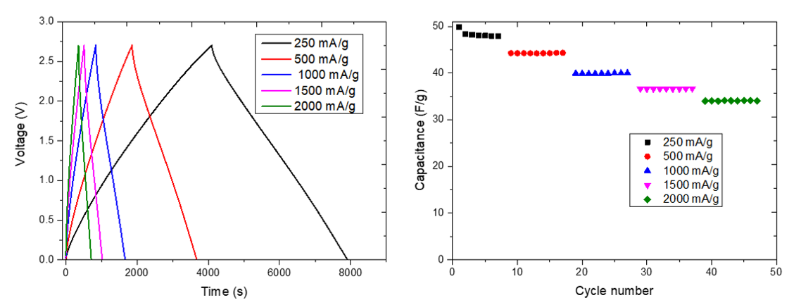
The long term cycling performance of the cells were also investigated. Over 10,000 cycles between 0 and 2.7 V at a rate of 500 mA/g, very little degradation of the capacitance was observed (Figure 5). Initially the capacitance did decrease, but levelled off around after around 500 cycles and showed roughly constant capacitance from that point forward. An energy density of approximately 40 Wh/kg was achieved during these cycles. The Coulombic efficiency was also high at approximately 99%.
To judge the performance of this new electrolyte, cells using a traditional 1M solution of tetrabutyl ammonium tetrafluoroborate (TBAB) in acetonitrile were also constructed using the same activated carbon electrodes. These cells were able to achieve a capacitance of 38-40 F/g when cycled at 500 mA/g. This shows that the the capacitance attained by the acetonitrile cells is similar to that of the microemulsion electrolyte. The rate capability of the acetonitrile electrolyte was better than the microemulsion electrolyte, retaining a high capacitance of 35 F/g whereas the microemulsion electrolyte only achieved 17 F/g. This rate capability could be improved by better matching the surface of the activated carbon to the microemulsion, either by refinement of the pore size or by adjusting the surfactant used and/or component ratios in the composition.
3 Conclusions
Using a microemulsion extends the electrochemical window of water to a point where it can be used as a supercapacitor electrolyte with no loss of voltage compared to standard systems based on organic solvents. In this study, we explored the effect of the widened electrochemical window on glassy carbon and platinum electrodes using a microemulsion electrolyte. Furthermore, an electrochemical double-layer capacitor was constructed from activated carbon electrodes and the new electrolyte. A significant increase in voltage was observed despite the electrolyte containing mostly water. Thus, microemulsion electrolytes will enable the fabrication of supercapacitors with similar performance to current technology, using low hazard and low cost materials.
4 Experimental methods
4.1 Materials
Electrode material slurries were prepared by mixing Activated carbon (85% by wt. Commodities NZ), 9% binder (PVDF, MTI Corporation) and 6% Super-P conductive carbon (99+% metals basis, Alfa Aesar). Slurries were ‘doctor-bladed’ onto graphite foil (thickness 0.127 mm, Ceramaterials) and dried in a vacuum oven at 120 Celcius for 12 hours. The specific loading of the active materials was approximately 11 mgcm-2
4.2 Electrolyte preparation
The composition of the electrolyte base was kept constant between cells. 84 wt% distilled water, 4 wt% Sodium dodecyl sulfate (SDS) (TCI, 99.9%), 9 wt% n-butanol (Sigma, reagent grade) and 3 wt% cyclohexane (Sigma, reagent grade) were mixed in a conical flask until a clear solution was observed indicating the formation of the microemulsion. Occasionally, sonication was utilised to speed up the formation of the microemulsion. After the formation of the microemulsion, NaCl (Fisher scientific) was added to give a concentration of 0.1 mol/kg. The surfactant free microemulsion was prepared in a similar fashion 26 wt% dichloromethane, 36.5 wt% ethanol (Sigma, reagent grade) and 37.5 wt% water with 0.1M KCl (Fisher scientific).
Acetonitrile (Sigma, anhydrous) electrolytes were prepared by mixing acetontirle and tetrabutylammonium tetrafluoroborate (Sigma, 99.9%) to a concentration of 1M in a nitrogen glovebox.
4.3 Cell assembly
Polyether ether ketone (PEEK) cells were used for all electrochemical tests. Custom PEEK rods with glassy carbon rod inserts were used as current collectors. Electrodes were placed inside the cell and glass microfiber (Grade GF/D, Whatman) were used as separators. Approximately 70 microliters of the electrolyte were used to wet the separator. All cell assembly was done on a bench top in ambient conditions.
For acetonitrile cells, assembly was done inside a nitrogen glovebox.
4.4 Electrochemical testing
Cyclic voltammetry (CV) experiments on full cells and Pt working electrodes were run using a potentiostat (eDAQ EA 160, ecorder-401), the glassy carbon experiments were done using a biologic VMP3 potentiostat. CVs done to determine electrochemical windows were done in a 3 electrode set up using a platinum-iridium alloy mesh or platinum mesh as the counter electrode, a silver wire as the reference electrode and either glassy carbon or platinum as the working electrode. All solutions were degassed by bubbling nitrogen through them for at least 20 minutes prior to the experiment. CV experiments on full supercapacitor cells were done using the anode as the reference and counter electrodes and the cathode as the working electrode. No degassing was performed prior to electrolytes being loaded into the cells. For acetonitirle cells, cells were taken out of the glovebox and wrapped in parafilm to prevent any exposure to air.
Galvanostatic charge-discharge experiments were performed using a battery analyser system (NEWARE BTS CT-4008-5V10mA-164, MTI Corp.).
References
- [1] Ander González, Eider Goikolea, Jon Andoni Barrena, and Roman Mysyk. Review on supercapacitors: Technologies and materials. Renewable and Sustainable Energy Reviews, 58:1189–1206, May 2016.
- [2] Cuimei Zhao and Weitao Zheng. A Review for Aqueous Electrochemical Supercapacitors. Frontiers in Energy Research, 3, 2015.
- [3] Zhoufei Yang, Jiarui Tian, Zefang Yin, Chaojie Cui, Weizhong Qian, and Fei Wei. Carbon nanotube- and graphene-based nanomaterials and applications in high-voltage supercapacitor: A review. Carbon, 141:467–480, January 2019.
- [4] Liumin Suo, Oleg Borodin, Tao Gao, Marco Olguin, Janet Ho, Xiulin Fan, Chao Luo, Chunsheng Wang, and Kang Xu. “Water-in-salt” electrolyte enables high-voltage aqueous lithium-ion chemistries. Science, 350(6263):938–943, November 2015.
- [5] Daniel P. Leonard, Zhixuan Wei, Gang Chen, Fei Du, and Xiulei Ji. Water-in-Salt Electrolyte for Potassium-Ion Batteries. ACS Energy Letters, 3(2):373–374, February 2018.
- [6] Liumin Suo, Oleg Borodin, Yuesheng Wang, Xiaohui Rong, Wei Sun, Xiiulin Fan, Shuyin Xu, Marshall A. Schroeder, Arthur V. Cresce, Fei Wang, Chongyin Yang, Yong-Sheng Hu, Kang Xu, and Chunsheng Wang. “Water-in-Salt” Electrolyte Makes Aqueous Sodium-Ion Battery Safe, Green, and Long-Lasting. Advanced Energy Materials, 7(21):1701189, 2017.
- [7] Maria R. Lukatskaya, Jeremy I. Feldblyum, David G. Mackanic, Franziska Lissel, Dominik L. Michels, Yi Cui, and Zhenan Bao. Concentrated mixed cation acetate “water-in-salt” solutions as green and low-cost high voltage electrolytes for aqueous batteries. Energy & Environmental Science, 11(10):2876–2883, 2018.
- [8] Yuanlong Shao, Maher F. El-Kady, Jingyu Sun, Yaogang Li, Qinghong Zhang, Meifang Zhu, Hongzhi Wang, Bruce Dunn, and Richard B. Kaner. Design and Mechanisms of Asymmetric Supercapacitors. Chemical Reviews, 118(18):9233–9280, September 2018.
- [9] J. Suárez-Guevara, V. Ruiz, and P. Gomez-Romero. Hybrid energy storage: High voltage aqueous supercapacitors based on activated carbon–phosphotungstate hybrid materials. Journal of Materials Chemistry A, 2(4):1014–1021, 2014.
- [10] Minghao Yu, Yongzhuang Lu, Haibing Zheng, and Xihong Lu. New Insights into the Operating Voltage of Aqueous Supercapacitors. Chemistry – A European Journal, 24(15):3639–3649, March 2018.
- [11] Jun Feng, Natasha A. Chernova, Fredrick Omenya, Lingyue Tong, Alok C. Rastogi, and M. Stanley Whittingham. Effect of electrode charge balance on the energy storage performance of hybrid supercapacitor cells based on LiFePO4 as Li-ion battery electrode and activated carbon. Journal of Solid State Electrochemistry, 22(4):1063–1078, April 2018.
- [12] D. Cericola, R. Kötz, and A. Wokaun. Effect of electrode mass ratio on aging of activated carbon based supercapacitors utilizing organic electrolytes. Journal of Power Sources, 196(6):3114–3118, March 2011.
- [13] Jing Peng, Nelly Margareth Cantillo, Kaitlyn McKensie Nelms, Lacey Roberts, Gabriel A. Goenaga, Adam E. Imel, Brian Barth, Mark D. Dadmun, Luke Heroux, Douglas Gordon Hayes, and Thomas A. Zawodzinski. Electron Transfer in Microemulsion-based Electrolytes. ACS Applied Materials & Interfaces, August 2020.
- [14] James F. Rusling and De-Ling Zhou. Electrochemical catalysis in microemulsions. Dynamics and organic synthesis1Dedicated to Prof. K.B. Oldham on the occasion of his retirement from Trent University.1. Journal of Electroanalytical Chemistry, 439(1):89–96, December 1997.
- [15] James F. Rusling. Green synthesis via electrolysis in microemulsions. Pure and Applied Chemistry, 73(12):1895–1905, January 2001.
- [16] Jianxin Gao and James F. Rusling. Electrochemical Catalysis of a 5-Endo-Trig Cyclization in Bicontinuous Microemulsions. The Journal of Organic Chemistry, 63(2):218–219, January 1998.
- [17] L. Demarconnay, E. Raymundo-Piñero, and F. Béguin. A symmetric carbon/carbon supercapacitor operating at 1.6V by using a neutral aqueous solution. Electrochemistry Communications, 12(10):1275–1278, October 2010.
- [18] Hui Xia, Ying Shirley Meng, Guoliang Yuan, Chong Cui, and Li Lu. A Symmetric RuO2/RuO2 Supercapacitor Operating at 1.6 V by Using a Neutral Aqueous Electrolyte. Electrochemical and Solid-State Letters, 15(4):A60–A63, January 2012.
- [19] Zhiguo Hou, Xueqian Zhang, Xiaona Li, Yongchun Zhu, Jianwen Liang, and Yitai Qian. Surfactant widens the electrochemical window of an aqueous electrolyte for better rechargeable aqueous sodium/zinc battery. Journal of Materials Chemistry A, 5(2):730–738, January 2017.
- [20] Chi-Chang Hu, Wei-Chun Chen, and Kuo-Hsin Chang. How to Achieve Maximum Utilization of Hydrous Ruthenium Oxide for Supercapacitors. Journal of The Electrochemical Society, 151(2):A281, January 2004.
- [21] Samuel Devese and Thomas Nann. Suppressed self-discharge of an aqueous supercapacitor using Earth-abundant materials. Journal of Electroanalytical Chemistry, 871:114307, August 2020.
Supporting Information
Electrochemical double layer capacitors using a microemulsion electrolyte
Fraser R Hughson, Rohan Borah, Thomas Nann*