![[Uncaptioned image]](/html/2011.03752/assets/x2.png)
![]()
|
|
Impact cratering in sand: Comparing solid and liquid intruders† |
| Rianne de Jong,a Song-Chuan Zhao,∗a,b, Diana García-González,a , Gijs Verduijn,a and Devaraj van der Meer a | |
|
|
How does the impact of a deformable droplet on a granular bed differ from that caused by a solid impactor of similar size and density? Here, we experimentally study this question and focus on the effect of intruder deformability on the crater shape. For comparable impact energies, we show that the crater diameter is larger for droplets than for solid intruders but that the impact of the latter results in deeper craters. Interestingly, for initially dense beds of packing fractions larger than 0.58, we find that the resultant excavated crater volume is independent of the intruder deformability, suggesting an impactor-independent dissipation mechanism within the sand for these dense beds. |
1 Introduction
Impacts of objects on sand and soils are regularly observed in nature. This is not only true on the small scale of e.g., raindrops, but equally on the very large scale with asteroid impacts, the craters of which are present on the Moon, Mars and even our own planet 1, 2. For planetary craters, it has often been assumed that the intruders are (at least initially) rigid in shape, and accordingly various lab-scale experiments were performed, for which similarities were found between the small craters caused by solid impactors on the laboratory scale and the planetary ones 3, 4, 5, 6. Recently, it was suggested that small scale solid intruders do not quite resemble asteroids, as the latter are expected to fluidize upon hitting the target. Pacheco-Vázquez & Ruiz-Suárez 7 studied impact of consolidated granular intruders on sand that disintegrate upon impact and found similarities with impact craters on the planetary scale 7, 8. Even the craters caused by liquid droplet impact were compared to large-scale craters 9 and it was found that crater dimensions in both cases follow similar scaling laws. Although many works indicate the importance of deformability, it remains unknown in what way the consistency of the impactor determines the crater shape. It is precisely this question that we will address in this work, by directly comparing the impact of a solid and a deformable liquid intruder of similar size and density on the laboratory scale.
A first clear difference between solid and liquid impacts is that the droplet continuously deforms upon impact until a maximum droplet spreading diameter is reached 10, 11, 12, 13, 14, 15, 9, 16, 17, 18. Consequently, as the droplet deforms upon impact, not all of the impact energy is transferred to the sand bed, but part of it is used for droplet deformation 16. Furthermore, during droplet impact liquid and grains may mix 10, 13, 15, 16. We will deal with the latter of these complicating factors by using hydrophobic sand to prevent mixing of liquid and grains, such that we focus solely on the effect of the deformability of the intruder. The first complicating factor is slightly harder to deal with and we will use the approach taken in our earlier work16, 17, 18 to estimate the portion of the impact energy that is used to excavate the crater from the measured crater depth. The craters will be studied using (high-speed) laser profilometry to measure typical crater dimensions such as the maximum crater diameter, the maximum depth and the excavated crater volume.
2 Experimental methods and results
In our experiments we compare two kinds of intruders: the first are deformable millimeter-sized water drops, mixed with food dye to increase contrast (mass fraction ) and the second are solid intruders of similar dimension and density as the water droplets, such that we explore the same range in parameter space for both intruder types. The diameter of the water drops is mostly and occasionally . Three sizes of opaque, spherical solid intruders are used, with diameters of , which consist of polypropylene or polyethylene and a white paint coating. The average mass of each intruder size are for increasing diameter, , mg and mg respectively. This results in intruder densities, , between and 19.
The impact velocity, , is varied in a range of by changing the release height and for every droplet is measured just before impact. For the solid intruders the impact velocity is conveniently computed from a calibrated height-velocity profile. The target consists of a bed of silane-coated (i.e., hydrophobic), soda-lime beads (specific density ) of two batches, of which the mean of the size distributions are and . The packing fraction of the bed, , is varied between and . Note that the results presented here focus mainly on the grains with 20. Prior to the experiments, the beads are dried in an oven around a temperature of for at least half an hour. We capture the deformation of the bed surface upon impact with an in-house-built high-speed laser profilometer, from which we acquire a dynamic crater profile, , by assuming axisymmetry. With the same laser and camera, and the help of a translation stage, both the substrate surface prior to impact and the final crater shape are obtained in 3D. By subtracting the initial height profile from the final one, and assuming axisymmetry, we obtain a radial profile, from which we acquire the crater dimensions. We refer to our earlier papers 16, 18 for more details on the experimental method.
2.1 Maximum crater diameter.
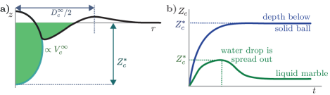
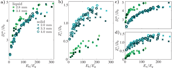
The diameter of the final crater shape, , obtained here as the radial position of the top of the crater rim (see Fig. 1(a)), is a typical measure for the target deformation after impact. As the size of solid and liquid intruders varies, we can compare them by non-dimensionalizing the final diameter with the initial intruder diameter and the kinetic energy just upon impact with the typical gravitational potential energy , corresponding to a cavity with dimensions dug into the sand 21.
As the portion of the impact energy that goes into sand deformation is smaller for deformable intruders, intuition suggests that for the same impact speed the resulting crater diameter should be smaller for the droplet than for the solid intruder impacts. In striking contrast to this expectation, one can observe in Fig. 2a that the crater diameter is larger when caused by a deformable intruder than by a solid one. This effect becomes even more pronounced when we take into account that, for drop impact, the spreading of the droplet consumes part of the initial impact energy. Using the estimate we derived earlier16, 17, 18, the sand deformation energy is given by for the droplets, where is the maximum crater depth discussed in greater detail in the next section. With this corrected impact energy (and taking for the solid intruder data), we find that the difference between crater diameters of solid and liquid impactors becomes even more pronounced (Fig. 2c). So, the simple hypothesis that a crater caused by solid intruders is larger in all directions than the one formed by a droplet does not hold. The opposite is true: the final crater is narrower for solid intruders than for droplets 22.
How does droplet spreading influence the crater diameter to such an extent that it becomes larger than that of a solid impactor? A first indication could be given by the maximum spreading diameter that the droplet reaches upon impact. In fact, an intuitive approach used in the literature10, 13, 2 (and implicitly also in Zhao et al.9) relates the crater diameter directly to the maximum droplet spreading diameter. In our experiments we however found that the crater diameter is already developing independently of drop deformation at a quite early stage of the impact 18. More specifically, when we compare the final crater diameter and maximum droplet spreading diameter for the same set of experiments, we find that they collapse with different parameters, indicating that the maximum droplet spreading and crater diameters are not directly related to one another, as evidenced in the Supplementary Material†
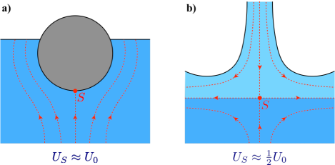
Although droplet spreading cannot directly account for the larger crater diameter for droplet impact, the observed difference between solid and liquid object impact must of course be related to the fact that the droplet will deform under forcing. It thereby can redirect the downward motion partly into horizontal motion: while the droplet penetrates into the bed, it deforms sideways and pushes grains radially outwards 7. It is instructive to compare the situation with the impact of solid and liquid intruders onto a liquid bath. There, a solid intruder will initially continue with a velocity close to the impact velocity 23, whereas a droplet will move into the bath with a much smaller initial velocity of maximally 24, indicating a rapid transformation of vertical into horizontal motion for the latter. Dynamically, the smaller velocity of the stagnation point in the case of droplet impact corresponds to a smaller stagnation pressure and therefore a smaller vertical forcing. From a potential flow perspective, as illustrated in Fig. 3, for the solid impactor the flow in the liquid bath resembles the dipolar flow around a solid object, whereas for the liquid impactor it resembles a stagnation point flow on the entire scale of the spreading droplet, similar to when a liquid jet impacts a quiescent liquid bath 25. These fundamentally different flow patterns generated in the substrate are (at least transiently) also expected to be present in the case of a sand bed and therefore may well explain the observed differences in crater diameter.
2.2 Maximum crater depth
As the droplet deforms and not all the inertial forcing will be directed downward, we can presume that the penetration depth of a drop will be smaller than that of a solid intruder. For the droplet experiments, the maximum crater depth, , needs to be observed during impact (Fig. 1): After the droplet has spread out maximally, the moment at which the crater depth can be measured, it will contract under surface tensional force and become a liquid marble26, the presence of which decreases the observed depth of the crater in the center. We therefore obtain from the dynamic profiles. Because for solid intruders the crater depth will remain unaltered as soon as the impactor comes to rest and they rarely get buried completely in our set of experiments, can simply be found by subtracting the intruder diameter from the central part of the profiles.
Plotting as a function of in Fig. 2b, we indeed observe that for the same impact energy the solid intruder craters become much deeper than the ones created by the impact of a droplet. This difference persists when we take into account that the spreading of the droplet consumes part of the initial impact energy by plotting the same data versus rather than (Fig. 2d).
2.3 Excavated volume
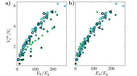
Knowing that exchanging a solid impactor for a deformable one simultaneously increases the crater diameter and decreases its depth makes one wonder what may happen with the total excavated volume. We quantify the crater volume as the void that is created into the granular bed after impact, i.e., by computing all the granular material that has been displaced from below the original surface of the bed before impact. To do so, we only consider the volume below , until the radial distance at which is reached (nearby the crater rim), i.e., the colored region sketched in Fig. 1a 27. In Fig. 4a, the excavated crater volume, normalized with the volume of the intruder , is plotted against the dimensionless impact energy. The crater volume for the solid intruders impacts is slightly but noticeably larger for all impact energies than for the droplet intruder cases. If we plot, however, the volume against the corrected impact energy, namely the non-dimensional sand deformation energy , we see that the data nicely collapses onto a single curve. This result shows that despite the fact that the horizontal and vertical crater dimensions differ significantly, the total energy going into crater formation gives rise to the same excavated volume for a solid and a deformable intruder. It suggests that for this set of experiments, the dissipation processes within the sand yield the same result for the dissipated energy during the impact of the two types of intruders, even if the details of the crater formation process are very different. This is even more evident when it is realized that the potential energy stored in the displaced sand volume is found to be less than of the impact energy, i.e., the crater formation process is heavily dominated by dissipation 28.
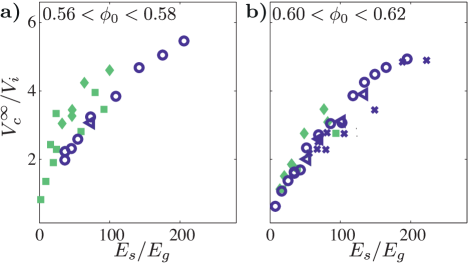
2.4 Packing fraction dependence.
Until here, we kept the packing fraction range limited to . However, in previous work 18 on drop impact on sand, we found that the crater shapes and the energy transferred to the sand greatly vary with packing density. Also for solid intruders, the crater shapes are altered with packing fraction as, e.g., discussed by Umbanhowar & Goldman 29, where it was found that the total displaced volume of sand (including the rim) goes from a compressed state for loose beds (i.e., the total displaced sand volume is smaller than the crater volume), crosses zero at a critical packing fraction (), to a dilated state for dense beds.
So the question is, what happens when we vary the packing fraction? The first observation is that for all attainable packing fraction ranges the crater diameter and depth behave similarly as was found for . The results for the excavated volume , however, reveal some subtle differences. In Fig. 5, all excavated volume data for packing fraction ranges from and is displayed and we observe that the data for solid and deformable intruders collapses with for the densest packed beds () as well. For the loose beds with , however, the droplet data lie slightly but consistently above the crater volumes formed by solid intruders 30.
What could be the reason for this clear packing fraction dependence? The answer may lie in the way that the sand bed responds, which changes significantly around a critical packing fraction 31, 32, 33, 29, 34, 35. Above the packing will dilate under forcing 36, but for loose beds () the substrate will respond compressibly until it is (locally) compressed to , and then start to flow. This is why is also known as the dilatancy onset.
For the loose beds, with , this suggests that the substrate will first relatively easily be compressed to upon impact, after which the majority of the dissipation between the grains will occur. This may set the difference between the crater volume of the solid and liquid impactor: the droplet can transfer its energy to the bed more effectively as it can move or deform the bed there where it experiences the lowest resistance, and thus the droplet will be a more effective “compressor", resulting in larger crater volume for the same sand deformation energy . Further work is necessary to see if this hypothesis holds, e.g., by impact of slightly deformable solid intruders, (such as hydrogels) of varying stiffness onto beds of varying packing density.
Finally, we also performed impact experiments on a substrate consisting of slightly smaller hydrophobic, soda-lime beads ( ), which gave very similar results as reported above. The only difference is that small packing fractions present a somewhat larger difference between the dimensionless excavated crater volume for droplets and solid impactors (when plotted as a function of ) than we reported for . In addition, for the smaller grain size the region in which is larger for droplets than for solid impactors extends to a somewhat higher packing fraction.
3 Conclusions
We directly compared craters formed by the impact of solid intruders and deformable droplets on a substrate consisting of spherical hydrophobic soda-lime beads. We found that the crater length scales differ for the two types of impactors: solid intruder impact results in deeper but narrower craters compared to the impact of deformable impactors. As explanation we proposed that, whereas for solid intruders the inertial forcing will be directed downward, for droplets the forcing is directed both downwards and sideways. This is consistent with the observations of Pacheco-Vázquez & Ruiz-Suárez 7 for their experiments of consolidated granular sphere impact onto a granular substrate. They observe that, as soon as their granular intruder breaks into pieces, i.e., its yield strength is overcome, the final crater becomes broader and shallower than for solid intruders of the same mass. Where they, however, find that the difference between the crater diameter of the granular intruder and the solid one is constant and independent of impact energy, in our case, the diameters of the solid and the deformable intruder impacts follow different power-law scalings. The exponent for a fit to the functional form is for the water drops and for the solid intruders . In addition, Pacheco-Vázquez & Ruiz-Suárez 7 found that the depth of the crater formed by a granular object goes towards a relatively constant value as soon as the intruder falls apart, whereas for our drops the crater depth increases with impact energy, see Fig. 2b.
Subsequently, we studied the resultant excavated crater volume and found surprisingly, that, for dense beds of , it is independent of the chosen intruder type. Since these types of impact are heavily dominated by dissipation, this indicates that the amount of dissipation with these dense sand beds can be characterized by the final excavated volume, irrespective of the detailed impact dynamics. Such a one-to-one relation between the excavated volume and the effective impact energy might provide a measure of the energy transfer for a deformable intruder impact by comparing its solid counterpart.
For loosely packed sand beds, we do observe an intruder-type dependence in the crater volume data, which we tentatively attribute to sand compressibility for these low packing fractions. Further research is needed to validate this idea.
Conflicts of interest
There are no conflicts to declare.
Acknowledgements
We thank Maarten Hannink and Stefan van der Vegte for their help in the solid intruder experiments. This work is financed by the Netherlands Organisation for Scientific Research (NWO) through a VIDI Grant No. 68047512.
Notes and references
- Melosh 1989 H. J. Melosh, Impact cratering: A geologic process, Oxford University Press, New York, 1989, vol. 11.
- Katsuragi 2016 H. Katsuragi, Physics of Soft Impact and Cratering, Springer Japan, 2016.
- Holsapple 1993 K. A. Holsapple, Annu. Rev. Earth Planet. Sci., 1993, 21, 333–373.
- Schmidt and Housen 1987 R. M. Schmidt and K. R. Housen, Int. J. Impact Eng., 1987, 5, 543–560.
- Amato and Williams 1998 J. C. Amato and R. E. Williams, Am. J. Phys., 1998, 66, 141–143.
- Walsh et al. 2003 A. M. Walsh, K. E. Holloway, P. Habdas and J. R. de Bruyn, Phys. Rev. Lett., 2003, 91, 104301.
- Pacheco-Vázquez and Ruiz-Suárez 2011 F. Pacheco-Vázquez and J. C. Ruiz-Suárez, Phys. Rev. Lett., 2011, 107, 218001.
- Bartali et al. 2013 R. Bartali, G. M. Rodríguez-Lin̂án, Y. Nahmad-Molinari, D. Sarocchi and J. C. Ruiz-Suárez, arXiv:1302.0259, 2013.
- Zhao et al. 2015 R. Zhao, Q. Zhang, H. Tjugito and X. Cheng, Proc. Natl. Acad. Sci., 2015, 112, 342–347.
- Katsuragi 2010 H. Katsuragi, Phys. Rev. Lett., 2010, 104, 218001.
- Marston et al. 2010 J. Marston, S. Thoroddsen, W. Ng and R. Tan, Powder Technol., 2010, 203, 223–236.
- Katsuragi 2011 H. Katsuragi, J. Fluid Mech., 2011, 675, 552–73.
- Delon et al. 2011 G. Delon, D. Terwagne, S. Dorbolo, N. Vandewalle and H. Caps, Phys. Rev. E, 2011, 84, 046320.
- Nefzaoui and Skurtys 2012 E. Nefzaoui and O. Skurtys, Exp. Therm. Fluid Sci., 2012, 41, 43 – 50.
- Emady et al. 2013 H. N. Emady, D. Kayrak-Talay and J. D. Litster, J. Colloid Interface Sci., 2013, 393, 369–76.
- Zhao et al. 2015 S. C. Zhao, R. de Jong and D. van der Meer, Soft Matter, 2015, 11, 6562–6568.
- Zhao et al. 2017 S. C. Zhao, R. de Jong and D. van der Meer, Phys. Rev. Lett., 2017, 118, 054502.
- de Jong et al. 2017 R. de Jong, S. C. Zhao and D. van der Meer, Phys. Rev. E, 2017, 95, 042901.
- 19 The solid intruders are painted white to make them opaque, such that they cause sufficient reflection of the laser light. The spheres of and mm consist of polypropylene and those of mm are made from polyethylene. For every size, we painted a batch of spheres, as the intruders are small and therefore easily lost during the experiments. The variation in density between individual spheres is mostly due to variation in the amount of paint on each of them, which is accounted for when calculating the impact energy of the intruder.
- 20 Note that the dimensions of the impact crater are expected to depend on and as the plastic properties of the granular bed (e.g., stiffness and friction) depend on those.
- 21 The dimensionless energy can also be written as a density ratio times the Froude number, i.e., .
- 22 Note that here, in contrast to what we reported in earlier work 16, 17, 18, the crater diameter data collapses irrespective of whether it is plotted against or , which is due to the fact that the data has been deliberately restricted to a narrow range of packing fractions.
- 23 More specifically, upon impact, the liquid will be set into motion by the intruder, giving rise to an added mass force that will decelerate the intruder. Assuming a similar density for intruder and target, the velocity of the intruder together with the virtual added mass can be approximated at .
- 24 A stagnation velocity of is the limiting case for a liquid jet impacting with a velocity on a pool. For a single drop it will be smaller and for a much shorter time duration of order . 25.
- Bouwhuis et al. 2016 W. Bouwhuis, X. Huang, C. U. Chan, P. E. Frommhold, C.-D. Ohl, D. Lohse, J. H. Snoeijer and D. van der Meer, J. Fluid Mech., 2016, 792, 850–868.
- Aussillous and Quere 2001 P. Aussillous and D. Quere, Nature, 2001, 411, 924–927.
- 27 Note that the intruder volume is of course subtracted. For droplet impacts, we assume that the liquid volume that may have splashed away is not significantly affecting this calculation.
- 28 In fact, also the percentage of momentum going into splashing of grains after drop impact on sand has been investigated and it was found that the splash momentum was only about of the initial droplet momentum before impact 37.
- Umbanhowar and Goldman 2010 P. Umbanhowar and D. I. Goldman, Phys. Rev. E, 2010, 82, 010301.
- 30 Remarkably, for these low packing densities, the data seems to collapse with the uncorrected dimensionless impact energy . We postulate that this is a coincidence since the energy consumed by drop deformation varies between and of the impact kinetic energy in this set of experiments.
- Thompson and Grest 1991 P. Thompson and G. Grest, Phys. Rev. Lett., 1991, 67, 1751–1754.
- Schröter et al. 2007 M. Schröter, S. Nägle, C. Radin and H. L. Swinney, Europhys. Lett., 2007, 78, 44004.
- Gravish et al. 2010 N. Gravish, P. B. Umbanhowar and D. I. Goldman, Phys. Rev. Lett., 2010, 105, 128301.
- Métayer et al. 2011 J.-F. Métayer, D. J. Suntrup III, C. Radin, H. L. Swinney and M. Schröter, Europhys. Lett., 2011, 93, 64003.
- Aguilar and Goldman 2016 J. Aguilar and D. I. Goldman, Nat Phys, 2016, 12, 278–283.
- Reynolds 1885 O. Reynolds, Lond. Edinb. Dubl. Phil. Mag., 1885, 20, 469–481.
- Long et al. 2014 E. J. Long, G. K. Hargrave, J. R. Cooper, B. G. B. Kitchener, A. J. Parsons, C. J. M. Hewett and J. Wainwright, Phys. Rev. E, 2014, 89, 032201.