Gamma Radiation Source Localization for Micro Aerial Vehicles with a Miniature Single-Detector Compton Event Camera
Abstract
A novel method for localization and estimation of compact sources of gamma radiation for Micro Aerial Vehicles is presented in this paper. The method is developed for a novel single-detector Compton camera, developed by the authors. The detector is extremely small and weighs only 40 g, which opens the possibility for use on sub-1 kg class of drones. The Compton camera uses the MiniPIX TPX3 CdTe event camera to measure Compton scattering products of incoming high-energy gamma photons. The 3D position and the sub-nanosecond time delay of the measured scattering products are used to reconstruct sets of possible directions to the source. The proposed method utilizes a filter for fusing the measurements and estimating the radiation source position during the flight. The computations are executed in real-time onboard and allow integration of the detector info into a fully-autonomous system. Moreover, the real-time nature of the estimator potentially allows estimating states of a moving radiation source. The proposed method was validated in simulations and demonstrated in a real-world experiment with a Cs137 radiation source. The approach can localize a gamma source without estimating the gradient or contours of radiation intensity, which opens possibilities for localizing sources in a cluttered and urban environment.
I INTRODUCTION
Localization of ionizing radiation sources has recently become the domain of autonomous mobile robots. Following the 2011 disaster at the Fukushima Daiichi Nuclear Power Plant (FDNPP), considerable efforts went into minimizing the exposure of human workers by sending Unmanned Ground Vehicles into potentially hazardous areas. Mapping a radiation distribution within an area is traditionally done with a dosimeter (measures intensity of radiation) while scanning the whole area. On the other hand, the search for compact sources is better done with sensors capable of estimating the direction to the source. The direction estimation is traditionally achieved by pixel radiation detectors (cameras) with sensor attachments, such as pinhole optics, coded apertures, and collimators [1]. In recent years, Compton cameras made an addition to the list of ways to estimate a set of directions to the source, however, without an external attachment to the sensor. A traditional Compton camera provides the direction to a source by measuring products of a Compton scattering reaction within two detectors (scatter and absorber). Information on the products is used to calculate a set of possible directions to the source in the form of a cone surface in 3D.
We aim to bring the Compton camera to the world of MAVs — sub- UAVs. With current state-of-the-art technologies, MAVs can fly autonomously in cluttered environments, such as urban and indoor environments and forests. An MAV can pursue an informed exploration of the environment towards the estimated position of the source if such a real-time estimate is available.
I-A Related work
Several UGVs have been deployed directly inside the damaged reactor buildings of FDNPP under remote control. Various radiation detection methods have been tested inside the power plant, including a coded aperture scintillator [2], a semiconductor digital dosimeter [3], a Compton event camera composed of two scintillators [4], and a time-of-flight gamma camera [5]. Ground-based robots offer higher payload capacity and the ability to carry heavier sensory equipment than most aerial vehicles. On the other hand, these robots tend to be relatively bulky, struggle to navigate the cluttered corridors and staircases inside the damaged buildings, and generally move slower than a multirotor aircraft.
UAVs have been utilized to map the spread of the radioactive material outside of the power plant. These range from large aircraft weighing more than equipped with heavy scintillation detectors [6, 7, 8] to compact multi-rotors suitable for flying along a pre-defined trajectory close to the ground [9, 10, 11]. Outside of Japan, several projects have employed UAVs for radiation intensity mapping around uranium ore mines [12, 13, 14].
In [15], multiple fixed-wing UAVs equipped with miniature scintillators are used for contour analysis of an irradiated area. Trajectory planning and data processing are performed offline, contrary to our approach, which estimates the position of the source in real-time during the flight. In [16], the contour analysis is tackled using a single multirotor UAV. The contour analysis uses a Gaussian mixture model to estimate multiple radiation sources’ positions with overlapping intensity fields. The projects mentioned above utilize unmanned vehicles to deliver a radiation detector into a hazardous environment. However, the approaches do not respond to measured data in real-time and thus do not exploit the mobility of UAVs to improve the measurement.
Active path-planning driven by the onboard measurements has been shown in [7] for an outdoor environment and in [17] for a GPS-denied indoor environment. Both of these works rely on a scintillator detector to estimate the radiation intensity in the UAV’s current position. As a result, the employed aerial platforms have to be large with a payload capacity exceeding . As in [7], the aerial platform is a unmanned aerial helicopter, which significantly limits its deployment conditions due to personal safety and considerable minimum distance to obstacles in the environment. Similarly, scintillating detectors were used in [17] on a mobile ground robot to map a cluttered environment and to search for radiation sources.
The lack of lightweight radiation detectors with immediate readout capability severely limits the application potential of aerial dosimetry. However, a new robotic methodology for motion planning and exploration needs to be developed to accommodate the proposed measurement system’s specifics. The proposed system is intended for outdoor and indoor environments, prompting a very compact and self-sufficient vehicle. We build upon our previous experience with indoor UAV deployment [18], where such radiation localization system could be used during exploration of mine shafts and caves [19, 20], in interiors of large buildings [21, 22], in forests [23] and in nuclear power plants [24].
, vector, pseudo-vector, or tuple , unit vector or unit pseudo-vector elements of the standard basis matrix inner product of , cross product of , element-wise product of , at the sample LKF system matrix, state vector, covariance time difference interval, [] in body-fixed, world, and camera frame signed angle between vectors (right-hand rule)
I-B Contributions
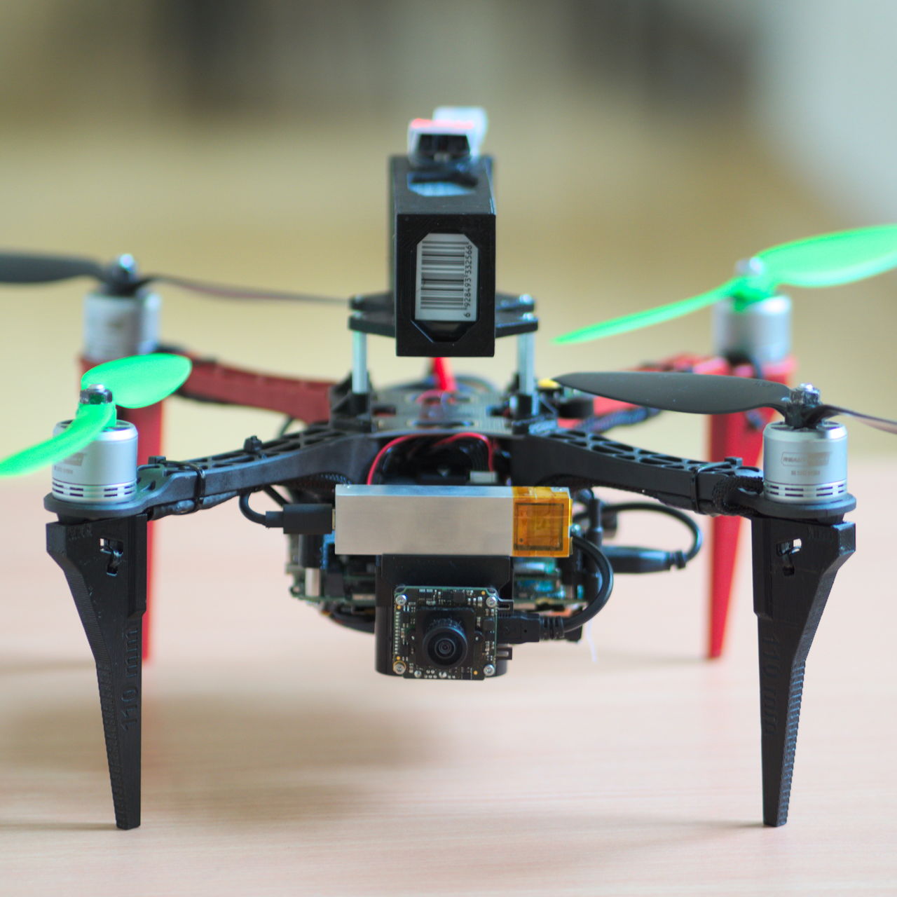
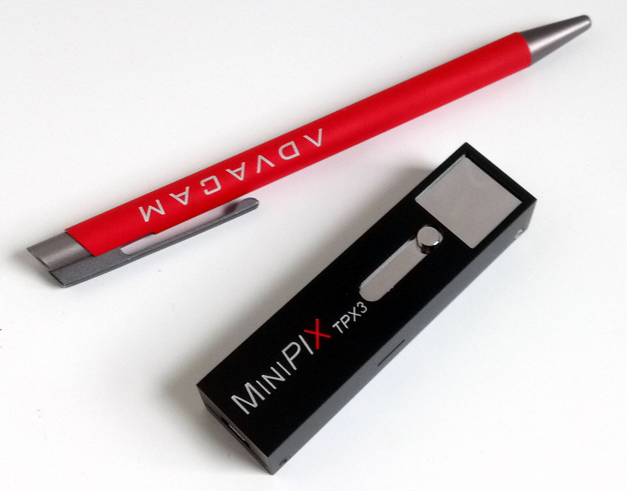
We present a novel method for gamma source radiation localization using a single-detector Compton camera [25]. The method utilizes an onboard position estimator of a UAV to estimate a real-time hypothesis of the radiation source position. The proposed method is executed in real-time such that the results can be used to drive an autonomous search algorithm. Unlike any existing solution, the system is deployable onboard Micro Aerial Vehicles thanks to the small form factor of the utilized Compton camera detector. The proposed approach is intended as an addition to an intensity-based estimation approach and the proposed method can, on its own, maintain a feasible hypothesis of a moving radiation source. The used MiniPIX TPX3 detector with Cadmium Telluride (CdTe) sensor can also detect and heavy-ion radiation and, therefore, can be used without changes to estimate gradients and contours of radiation intensity. Even more, particle tracks can be classified [1] to deduce the nature of the radiation source.
II TIMEPIX3 COMPTON CAMERA
The process of recording and imaging ionizing gamma radiation is very different from the near-visible light spectrum photography [1]. Refractive optical lenses cannot be made for such energies, and reflective optics (Kirkpatrick-Baez, Walter, Lobster-eye) are limited to energies not exceeding by the reflectivity of the used mirror materials such as gold and silicon. Pinhole gamma cameras are a viable option. However, their Field of View (FOV) is narrow, and the aperture shield absorbs a valuable portion of the incoming particles.
Compton cameras use the Compton scattering effect (see Fig. 2) to reconstruct a projection of a radioactive source [26]. Typically, a Compton camera consists of two sensors. The first detector, a scatterer, witnesses the Compton scattering effect in its sensor by capturing the bi-product of the reaction — the electron . The electron is captured immediately upon its creation. The second sensor is placed behind the first and is dedicated to capturing the scattered photon through the photo-electric effect. When both detectors detect the scattering products, they simultaneously measure the energy and the 3D position of the particles. According to Compton, 1923 [27], the relation of energies of the particles to the scattering angle is modelled as
| (1) |
where are the energies of the incoming and scattered photon (), is the energy of the electron (), is the electron rest mass, and is the speed of light in vacuum. Since Compton scattering is a radially symmetrical effect, the reconstruction of yields a set of possible incoming directions that forms a cone surface.
Contrary to recent works [4, 8, 28], we employ only a single sensor to measure the scattering products [25]. Using cutting-edge innovations in the field of particle imaging, we employ the Timepix3 detector [29] as part of the MiniPIX TPX3 event camera with a thick CdTe sensor 111https://advacam.com/camera/minipix-tpx3. The thick semiconductor sensor is capable of causing the scattering effects, as well as capturing the products. Thanks to the detector’s event camera operation mode, both bi-products are timed with sub-nanosecond accuracy, and the depth of the event within the sensor is calculated. In contrast with traditional frame-based cameras, event-driven cameras output a continuous stream of data generated by the active (hit) pixels. A similar trend emerged in the visible-light camera field [30]. Timepix3 promises a similar impact in the field of aerial radiation detection, as its essential properties are perfectly suited for dynamically flying MAVs.
The coincidence detection window is set to , which is the maximum time difference of two coinciding particles being measured at the opposite side of the CdTe at . The detection window is specific to this particular sensor and should be adjusted for different thicknesses, materials, and bias voltages.
II-A Reconstructing the set of directions to the source
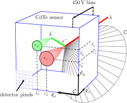
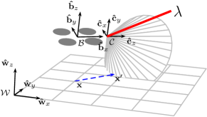
Table I summarizes the mathematical notation used throughout this work and Fig. 4 provides an illustration of the used coordinate systems. Ionizing radiation separates electrons (ionization) from the CdTe sensor material in the location of absorption. The newly created electron cloud is accelerated by a electric potential towards one facet of the CdTe sensor where the charge is measured by individual pixels of the Timepix3 detector. Figure 3 shows the charge-gathering process within the sensor. The and coordinates of the events are obtained by calculating the centroids of the respective pixel tracks (see Fig. 5). The z-coordinates and are unknown. However, it is possible to estimate the relative difference along the using the measured time-difference of the events. Although the absorption of and happens virtually at the same time222The speed of a gamma photon through CdTe material is near the speed of light in vacuum and therefore can be neglected., the charge-gathering causes a delay between the measured electron clouds. The relative z-distance is obtained as
| (2) |
where and are the times of arrival of the electron clouds from the electron and photon, respectively, and = = is the charge-gathering speed through the CdTe sensor with bias333The charge gathering speed is obtained empirically by analyzing tracks of muons from a cosmic radiation.. The absence of a precise absolute z-axis coordinate of the cone origin within the camera frame is inconsequential. It results only in a shift of the resulting cone surface, which can be neglected compared to the real-world distances involved. Only the difference between the scattering products along is significant for estimating the cone parameters. Therefore, coordinates of the electron and the secondary photon events in the camera frame are considered as
| (3) | ||||
| (4) |
In order to reconstruct the scattering angle , we convert the measured particle energies from () to () as
| (5) | ||||
| (6) |
and calculate the scattering angle using (1) as:
| (7) |
Finally, the cone parameters are the cone origin , the direction , and the inner angle .
III RADIATION SOURCE STATE ESTIMATION
Estimating the direction to the source is typically done under assumptions that do not apply in scenarios involving mobile robots. The camera position is often fixed during the whole measurement, and all the data are processed at once after the measurement [26, 28]. In other cases, the camera needs to be stationary to complete a single measurement set (tens of seconds) before it can be moved further [4, 8]. However, the estimation should be conducted continuously without stopping to utilize the advantages of multirotor helicopters fully. Moreover, in all the previous works involving a mobile robot, the used camera was a heavy device, which required the use of a large UGV or UAV. We aim to bring the Compton camera detector to the domain of MAVs. With appropriate onboard localization and mapping systems, such an MAV can automatically perform the search for an ionizing radiation source. However, this requires the MAV to automatically estimate the source’s position onboard in real-time to incorporate newly acquired data on the fly. Here we present our initial method developed for a single radiation source localization.
The proposed method relies on the Linear Kalman Filter (LKF) to estimate a hypothesis and a covariance of the source’s position. However, the LKF is not natively able to accept the measured cone surfaces as a vector of measurement. To tackle this issue, we assume that the optimal correction would move the hypothesis orthogonally in the cone surface direction. Such corrections behave idempotently under ideal conditions. Applying such a correction requires a novel approach of using LKF by defining an orthogonal projection to the cone surface.
III-A Orthogonal projection to a cone surface
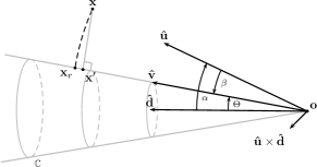
Projecting the LKF hypothesis orthogonally to the cone surface to obtain is illustrated in Fig. 6. Vector from the origin of the cone to the given point is denoted as . Firstly, we find the angle between the cone direction and as . Then, the angle between the cone surface and the desired orthogonal projection of to the cone surface is . To find the projection, we first find by rotating around the vector by the angle . The vector towards the projection is then constructed as . Finally, the orthogonal projection of on the cone surface is:
| (8) |
III-B Linear Kalman Filter
LKFs filter uses a model with the hypothesis and hypothesis covariance :
| (9) |
where is designed for a stationary 3D target. Measurement noise covariance with the correction being applied in the direction of the axis is defined as
| (10) |
where is used to weigh the correction in the direction to the cone surface. The rest of the matrix is designed to mitigate corrections for other directions. This canonical covariance is then rotated every time to align with the vector as where is a rotation matrix corresponding to rotation around the axis by the angle . An obtained measurement is then the projection and the covariance .
Two variants of the filter were tested: the fully-3D approach presented above, and a simplified 2D approach in which we assume that the radiation source is located on the ground. In the latter case, we project the hypothesis onto the ground plane after each correction.
Initialization of the LKF hypothesis cannot be done using the first arriving measurement as typical. To tackle this issue, we first gather cone surfaces with different points of origin. The gathering can be done using one of many exploration schemes, e.g., a traditional gradient-based exploration using particle intensity measurements as heuristics or flying a pre-determined sweeping path. With the first cones measured, we initialize the filter by optimizing for a point , which has the minimum square distance to the cones’ surfaces. Firstly, we must define the distance to a cone surface.
III-C Distance to a cone surface
Given a point such that ( is situated behind the cone origin), the distance to the cone surface is trivial:
| (11) |
Otherwise, the distance is expressed as
| (12) |
III-D Finding the closest point to multiple cone surfaces
The state estimator’s initialization is done by finding the closest point to the first N cone surfaces. The point is found by minimizing the squared distance to each cone surface while satisfying geometric constraints:
| (13) |
| (14) | ||||||
| (15) |
The constraint (15) is used optionally in the case of the 2D estimator to enforce the search for a source near the ground plane.
This optimization problem is a nonlinear least-squares problem, which makes finding a near-optimum solution impractical and time-consuming. However, we do not need to solve this problem quickly or in fast succession, and the solution is used only for initialization. Therefore, we utilize the Sequential Least-Squares Programming optimization method. The Jacobian of the criterion is calculated analytically. The problem takes approx. to solve for on an average onboard computer.
IV EXPERIMENTS
The approach was verified in realistic simulations using the Gazebo/ROS simulator. The Compton camera is modeled by combining real-time Monte-Carlo ray tracing [1]. Randomized simulations suggest that the proposed method is capable of initializing and further estimating the 3D position of the radiation source with no prior knowledge. However, the UAV should conduct motion orthogonally to the direction of the source. Otherwise, both the LKF initialization and the LKF correction methods result in singular solutions that fail to provide a full 3D position of the source. Similarly, the estimator fails when the UAV is stationary. This can be explained using the principles of the proposed method. When the UAV is stationary, all the cones originate from the same point. Therefore, the information extracted from multiple cones only provide data regarding the direction to the source. When the UAV conducts a motion directly towards the radiation source, again, the information extracted from the cones do not provide us with other than direction data. However, if the UAV moves orthogonally to the direction to the source, a non-trivial intersection of multiple cones can exist (if they originate from different 3D positions) and therefore, the 3D position of the source can be estimated. We can estimate the position of the source even in situations where traditional gradient-based method might fail, e.g., in urban environment. The proposed method could be used as an addition to the intensity-based methods, that can utilize the same Timepix3 detector. The orthogonal motion can be realized, e.g., by encircling the estimated hypothesis.
The presented two practical tests were conducted in cooperation of Advacam (developer of the MiniPIX TPX3 detector), the CTU (developer of the proposed method and the aerial system) and the Czech Metrology Institute (provider of the sample radiation sources). Only a few experiments were conducted due to the autumn/winter conditions in our country and the current social distancing rules, that have made such real-world tests increasingly difficult to organize.
IV-A Simulations
A real-time ray tracing simulation model proposed previously in [1] was used to evaluate the proposed localization method in conjunction with the realistic Gazebo/ROS robotics simulator. The DJI F330 quadrotor was modeled (see Fig. 7) and provided as a part of the MRS UAV system [18]. Development of a research strategy is not in the scope of this paper, hence we evaluate the localization method using the following naive search strategy:
-
1.
the UAV encircles a designated area until a hypothesis is initialized by Eq. (13),
-
2.
the UAV then proceeds to encircle the hypothesis, updating the LKF with the incoming measurements,
-
3.
if more than 3 cones in a row exhibit an outlier condition, the hypothesis is reset using Eq. (13).
Simulations show that the proposed method is able to localize a radiation source even with the naive search strategy. Moreover, the proposed localization method is even suitable for real time tracking of a moving \isotope[137]Cs radiation source. As shown in Fig. 8, the UAV is able to track a radiation source moving at the speed of . In the case of the source, the average rate of detected Compton cones was . In can be observed that a steady tracking is achieved even with the source, despite a lack of a specialized model in the LKF for a moving target. The simulation software together with an example scenarios is provided as open source at https://github.com/rospix.
IV-B Unmanned aerial vehicles
The first verification of the MiniPIX detector onboard a UAV was conducted using a general-purpose quadrotor helicopter built upon the Tarot 650 frame and equipped with Intel NUC-i7 onboard computer. Figure 9a depicts the UAV in mid-air. The Ouster OS1-16 3D LiDAR was used for ground truth localization and mapping together with the A-LOAM SLAM [31]. Furthermore, the UAV was also equipped with a wide-angle RGB camera to aid with data visualization. These sensors are not required for the proposed approach. The only requirement is the access to real-time 3D position and orientation state estimate of the UAV. Such a state estimate is a requirement for any autonomous mission. It can be accommodated by, e.g., a Global Navigation Satellite System (GNSS) receiver coupled with an Inertial Measurement Unit (IMU) and a magnetometer, or by a visual-inertial navigation system such as [32]. Therefore, the Compton camera system can be employed on much smaller UAV thanks to its small weight and size. The design and size of the UAV body is more limited by the localization sensor suite rather the by the radiation detector. The UAV utilized the open-source MRS UAV system444http://github.com/ctu-mrs/mrs_uav_system[18] in ROS for automatic control and state estimation.
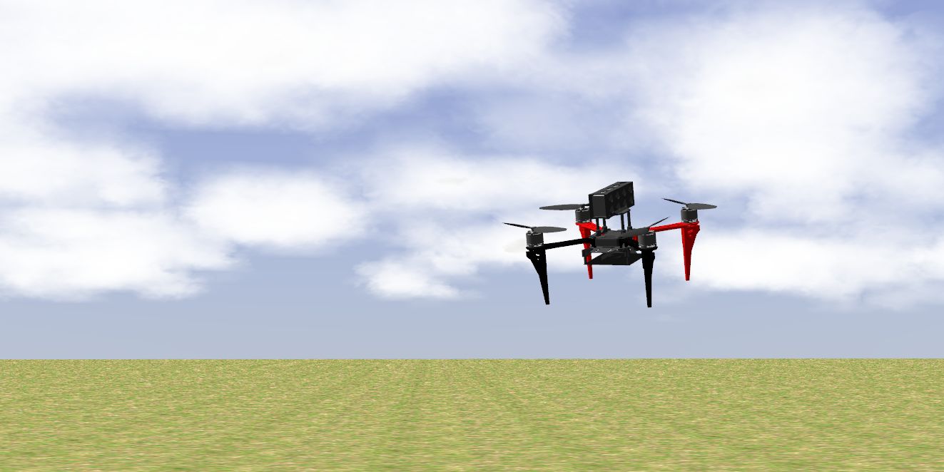
In the pursuit of miniaturization, a second experiment was conducted using the DJI F330 UAV (see Fig. 11a), weighting approx. . The UAV also conducted an autonomous flight, however, this time using a monocular visual SLAM, the VINS mono [32]. A wide-angle greyscale camera was used for localization in real-time.
IV-C Compton camera
The Compton camera is built upon the Timepix3 detector [29] with a CdTe sensor. CdTe sensors are exceptionally sensitive to high-energy gamma rays. The sensitivity to high-energy outweighs the small size (therefore small effective volume) of the sensor since only high-energy can travel hundreds of meters through the air without being absorbed. This allows sensing the sources from a further distance than using traditional detectors. The Timepix3 detector with thick CdTe sensor can detect photons ranging from 5 to with relatively high quantum efficiency especially for Compton scattering events. The miniaturized Timepix3-based detector MiniPIX TPX3 CdTe with incorporated data acquisition, calibration and event reconstruction software layers was developed by Advacam (see Fig. 1). The device does not require any cooling and can operate at room temperature. The Compton camera payload weighs and has dimensions of . The processing software is implemented in ROS and is available as open-source.
IV-D Experimental environment
These preliminary tests were conducted in area with a single \isotope[137]Cs source with activity of ( decay events per second). This was a relatively weak source, sending only photons at distance.
The first real-world test555The first test video: https://youtu.be/oH4jMMHfGVA was conducted under autonomous localization, mapping, and control, using the Tarot 650 UAV. A human operator provided the UAV with control waypoints, and the UAV followed them with speed. The UAV first conducted a sweeping flight while gathering the first 5 cone surfaces for initialization. After the LKF was initialized, it started encircling the current hypothesis. Such a strategy shows success in simulations. After successfully localizing the source, the estimator can adapt to the potentially changing position of the source. Figure 9 depicts the 3D map of the environment with the hypothesis showed as a red cube surrounded by a covariance ellipsoid. A yellow cube marks the ground truth position of the source.
The real-world test666The second test video: https://youtu.be/t6ayhHJ9z5k was conducted using the miniaturized UAV, the DJI F330. Again, the flight was conducted autonomously. This time, the point of the experiment was to test an updated version of the MiniPIX TPX3 detector API, developed specifically for detecting the Compton coincidences within the embedded hardware of the detector. Therefore, the UAV was tasked to autonomously encircle the already known position of the radiation source. Figure 11 depicts the UAV in mid-air, together with a snapshot of a 3D visualization of the recorded data.
Full-flight data from the experiments, including the RAW sensor data, localization data, LiDAR point clouds and camera images are available on the website http://mrs.felk.cvut.cz/radron-icuas in the form of rosbag files.
IV-E Results
Statistics of event occurrences observed during the experiments is shown in Table II. Figure 10 shows plots of the estimated 3D and 2D position of the gamma source in comparison to the ground truth. The hypothesis was correctly estimated near the ground truth after gathering just 15 Compton events. The experimental data show the estimator system working as expected. Future work should emphasize on rejecting outliers. Outliers can occur due to the omnipresent radiation background, even though occurrence of coincidences in the radiation background is extraordinarily rare. The detector registers only approx. 10 particles per second due to the radiation background, the chance of two background particles coinciding within the time frame of approx. is extremely low. The largest source of outliers lies in the uncertainty of origin of the already detected two coinciding particles. In some cases their type (electron, scattered photon) can be deduced from the measured energies using, e.g., the knowledge of the Compton edge for a known isotope. However, if both measured energies lie in the Compton continuum, the particle type is ambiguous. Moreover, even if the incoming photon comes from a known direction, back-scattering can make the measured by-products appear as incoming from an opposite direction. However, despite the occasional outliers, the estimator performed well despite the tested radiation source’s low activity. It must be noted, that majority of the measured signal, that can be seen in the provided videos and in the provided datasets, is a valid measurement of the incoming gamma photons, not of a background radiation. A majority of the signal originates from photons measured by pure photo-absorption, therefore, the signal does not produce coinciding particles used for Compton reconstruction. Nevertheless, the signal could be used for traditional intensity-based estimation [17], since the CdTe Timepix3 detector is fully capable to serve as a dosimeter. The method proposed in this manuscript aims to provide an additional information that could aid the traditional state-of-the-art methods, without the need for extra hardware.
| Event count | Rate [s-1] | Relative share | |
|---|---|---|---|
| Photoelectric | 6073 | 24.29 | 0.996 |
| Compton | 18 | 0.072 | 0.003 |
| Background | 8 | 0.032 | 0.001 |
| Photoelectric | 5315 | 21.26 | 0.996 |
| Compton | 18 | 0.072 | 0.003 |
| Background | 4 | 0.016 | 0.001 |
V LESSONS LEARNED AND FUTURE WORK
The presented results are a pilot work for a project for autonomous localization and tracking of compact ionizing radiation sources by Micro Aerial Vehicles. Several significant challenges have been identified that are yet to be tackled before the solution becomes fully autonomous and reliable. The single-detector Compton camera should be compared to a multi-sensor stack. Although the proposed single-detector variant offers a significantly simpler hardware solution, the angular resolution is worse than with a sensor stack. Moreover, reconstruction of cone surfaces using (7) should benefit from outlier rejection using the values of . Priors of can be estimated in real-time by analyzing the spectrum, a type of incoming particles. Also, the state estimation hypothesis should be generalized to a mixture of distributions. In combination with the observed complex 3D map of the environment, Monte-Carlo methods such as the particle filter should be explored. If available, prior knowledge of the environment structure, e.g., wall material and thickness, should also be utilized by the estimator.
We pursue the use of MAVs equipped with monocular visual SLAM (see Fig. 1). Autonomous planning methods should simultaneously explore an unknown environment while maximizing the yield of information gathered by the Compton camera. This task shares goals with the Defense Advanced Research Projects Agency (DARPA) SubT challenge777https://www.subtchallenge.com in which the authors participate. Simulations show that the multi-MAV system benefits significantly from sharing the measured data between the MAV [33]. We aim to utilize swarms of MAVs to increase the baseline of the distributed sensor, which increases the convergence speed of the estimator.
VI CONCLUSIONS
We have showcased a novel approach for localization and position estimation of a gamma radiation source using a miniature single-detector Compton camera on an Micro Aerial Vehicle. The proposed method of estimating the source’s position utilizes the particle physics interactions within the CdTe sensor in conjunction with a Linear Kalman Filter. A novel method of the filter initialization is proposed, given the Compton camera detector’s unique form of measurements. Moreover, a novel iterative-based correction method is proposed to fuse the measurements in the form of a cone surface. The methods were validated by real-world experiments showing promising results that were, until now, the domain of heavy-lifting aircraft. Gazebo/ROS simulation plugin for the Compton camera and the processing software is provided as open-source888http://github.com/rospix to allow and motivate research on autonomous systems using the Compton camera detector.
ACKNOWLEDGMENT
This work was done on behalf of Medipix3 collaboration, was supported by TACR project no. FW01010317, and by CTU grant no SGS20/174/OHK3/3T/13.
References
- [1] T. Baca, M. Jilek, P. Manek, et al., “Timepix Radiation Detector for Autonomous Radiation Localization and Mapping by Micro Unmanned Vehicles,” in 2019 IEEE/RSJ International Conference on Intelligent Robots and Systems. IEEE, 2019, pp. 1–8.
- [2] K. Ohno, S. Kawatsuma, T. Okada, et al., “Robotic control vehicle for measuring radiation in Fukushima Daiichi Nuclear Power Plant,” in 2011 IEEE International Symposium on Safety, Security, and Rescue Robotics. IEEE, 2011, pp. 38–43.
- [3] K. Nagatani et al., “Emergency response to the nuclear accident at the Fukushima Daiichi Nuclear Power Plants using mobile rescue robots,” Journal of Field Robotics, vol. 30, no. 1, pp. 44–63, 2013.
- [4] Y. Sato, Y. Terasaka, W. Utsugi, et al., “Radiation imaging using a compact Compton camera mounted on a crawler robot inside reactor buildings of Fukushima Daiichi Nuclear Power Station,” Journal of Nuclear Science and Technology, vol. 56, no. 9-10, pp. 801–808, 2019.
- [5] H. Kinoshita, R. Tayama, E. Y. Kometani, et al., “Development of new technology for Fukushima Daiichi nuclear power station reconstruction,” Hitachi Review, vol. 63, no. 4, pp. 183–190, 2014.
- [6] Y. Sanada et al., “Aerial Radiation Monitoring Around the Fukushima Dai-ichi Nuclear Power Plant Using an Unmanned Helicopter,” Journal of environmental radioactivity, vol. 139, pp. 294–299, 2015.
- [7] J. Towler, B. Krawiec, and K. Kochersberger, “Radiation mapping in post-disaster environments using an autonomous helicopter,” Remote Sensing, vol. 4, no. 7, pp. 1995–2015, 2012.
- [8] J. Jiang, K. Shimazoe, Y. Nakamura, et al., “A prototype of aerial radiation monitoring system using an unmanned helicopter mounting a GAGG scintillator Compton camera,” Journal of Nuclear Science and Technology, vol. 53, no. 7, pp. 1067–1075, 2016.
- [9] J. MacFarlane, O. Payton, A. Keatley, et al., “Lightweight aerial vehicles for monitoring, assessment and mapping of radiation anomalies,” Journal of environmental radioactivity, vol. 136, pp. 127–130, 2014.
- [10] G. Christie, A. Shoemaker, et al., “Radiation search operations using scene understanding with autonomous UAV and UGV,” Journal of Field Robotics, vol. 34, no. 8, pp. 1450–1468, 2017.
- [11] P. G. Martin, S. Kwong, N. Smith, Y. Yamashiki, O. D. Payton, et al., “3D unmanned aerial vehicle radiation mapping for assessing contaminant distribution and mobility,” International Journal of Applied Earth Observation and Geoinformation, vol. 52, pp. 12–19, 2016.
- [12] O. Salek, M. Matolin, and L. Gryc, “Mapping of radiation anomalies using UAV mini-airborne gamma-ray spectrometry,” Journal of environmental radioactivity, vol. 182, pp. 101–107, 2018.
- [13] A. Keatley, P. Martin, K. Hallam, O. Payton, R. Awbery, F. Carvalho, J. Oliveira, L. Silva, M. Malta, and T. Scott, “Source identification of uranium-containing materials at mine legacy sites in Portugal,” Journal of Environmental Radioactivity, vol. 183, pp. 102–111, 2018.
- [14] P. Martin, O. Payton, J. Fardoulis, et al., “The use of unmanned aerial systems for the mapping of legacy uranium mines,” Journal of environmental radioactivity, vol. 143, pp. 135–140, 2015.
- [15] J. Han, Y. Xu, L. Di, and Y. Chen, “Low-cost multi-UAV technologies for contour mapping of nuclear radiation field,” Journal of Intelligent & Robotic Systems, vol. 70, no. 1-4, pp. 401–410, 2013.
- [16] A. A. R. Newaz, S. Jeong, H. Lee, H. Ryu, and N. Y. Chong, “UAV-based multiple source localization and contour mapping of radiation fields,” Robotics and Autonomous Systems, vol. 85, pp. 12–25, 2016.
- [17] F. Mascarich, T. Wilson, C. Papachristos, and K. Alexis, “Radiation source localization in GPS-denied environments using aerial robots,” in 2018 IEEE ICRA. IEEE, 2018, pp. 6537–6544.
- [18] T. Baca, M. Petrlik, M. Vrba, V. Spurny, R. Penicka, et al., “The MRS UAV System: Pushing the Frontiers of Reproducible Research, Real-world Deployment, and Education with Autonomous Unmanned Aerial Vehicles,” Journal of Intelligent & Robotic Systems, vol. 102, no. 26, pp. 1–28, May 2021.
- [19] T. Roucek, M. Pecka, P. Cizek, T. Petricek, et al., “DARPA Subterranean Challenge: Multi-robotic exploration of underground environments,” in IEEE MESAS, vol. 11995, 2019, pp. 274–290.
- [20] M. Petrlik, T. Baca, D. Hert, M. Vrba, T. Krajnik, and M. Saska, “A Robust UAV System for Operations in a Constrained Environment,” IEEE Robotics and Automation Letters, vol. 5, 4 2020.
- [21] V. Kratky, P. Petracek, et al., “Autonomous reflectance transformation imaging by a team of unmanned aerial vehicles,” IEEE Robotics and Automation Letters, vol. 5, no. 2, pp. 2302–2309, 4 2020.
- [22] M. Saska, D. Hert, T. Baca, V. Kratky, and T. Nascimento, “Formation Control of Unmanned Micro Aerial Vehicles for Straitened Environments,” Autonomous Robots, pp. 1573–7527, 2020.
- [23] P. Petracek, V. Walter, T. Baca, and M. Saska, “Bio-Inspired Compact Swarms of Micro Aerial Vehicles without Communication and External Localization,” Bioinspiration & Biomimetics, 2020.
- [24] V. Kratky, P. Petracek, T. Baca, and M. Saska, “An Autonomous Unmanned Aerial Vehicle System for Fast Exploration of Large Complex Indoor Environments,” Submitted to Journal of Field Robotics, 2020, available online: http://mrs.felk.cvut.cz/data/papers/darpa_urban.pdf.
- [25] D. Turecek, J. Jakubek, E. Trojanova, and L. Sefc, “Single layer Compton camera based on Timepix3 technology,” Journal of Instrumentation, vol. 15, no. 01, p. C01014, 2020.
- [26] ——, “Compton camera based on Timepix3 technology,” Journal of Instrumentation, vol. 13, no. 11, p. C11022, 2018.
- [27] A. H. Compton, “A quantum theory of the scattering of X-rays by light elements,” Physical review, vol. 21, no. 5, p. 483, 1923.
- [28] F. Terzioglu, P. Kuchment, and L. Kunyansky, “Compton camera imaging and the cone transform: a brief overview,” Inverse Problems, vol. 34, no. 5, p. 054002, 2018.
- [29] T. Poikela, J. Plosila, et al., “Timepix3: a 65K channel hybrid pixel readout chip with simultaneous ToA/ToT and sparse readout,” Journal of instrumentation, vol. 9, no. 05, p. C05013, 2014.
- [30] B. Kueng et al., “Low-latency visual odometry using event-based feature tracks,” in 2016 IEEE/RSJ International Conference on Intelligent Robots and Systems. IEEE, 2016.
- [31] J. Zhang and S. Singh, “LOAM: Lidar Odometry and Mapping in Real-time,” in Robotics: Science and Systems, vol. 2, no. 9, 2014.
- [32] T. Qin, P. Li, and S. Shen, “Vins-mono: A robust and versatile monocular visual-inertial state estimator,” IEEE Transactions on Robotics, vol. 34, no. 4, pp. 1004–1020, 2018.
- [33] P. Stibinger, T. Baca, and M. Saska, “Localization of Ionizing Radiation Sources by Cooperating Micro Aerial Vehicles With Pixel Detectors in Real-Time,” IEEE Robotics and Automation Letters, vol. 5, pp. 3634–3641, 4 2020.