Magnetic Field Simulations Using Explicit Time Integration With Higher Order Schemes
Abstract
A transient magneto-quasistatic vector potential formulation involving nonlinear material is spatially discretized using the finite element method of first and second polynomial order. By applying a generalized Schur complement the resulting system of differential algebraic equations is reformulated into a system of ordinary differential equations (ODE). The ODE system is integrated in time using the explicit Euler scheme, which is conditionally stable by a maximum time step size. To overcome this limit, an explicit multistage Runge-Kutta-Chebyshev time integration method of higher order is employed to enlarge the maximum stable time step size. Both time integration methods are compared regarding the overall computational effort.
keywords:
Eddy currents, explicit Euler scheme, Runge-Kutta-Chebyshev quadrature, transient magneto-quasistatics1 Introduction
The simulation of magneto-quasistatic (MQS) field problems is crucial in the design process of electric machines, transformers and any other devices in the low frequency regime. Usually, these applications have material coefficients, which differ by many magnitudes through the computational domain like e.g. the change of the conductivity through the rotor, air-gap and stator of an electric engine. Furthermore, often some conductive parts of the problem are ferromagnetic with a nonlinear B-H-characteristic.
Spatial discretization of MQS field problems based on a magnetic vector potential formulation using the finite element method (FEM) yields nonlinear infinitely stiff differential-algebraic equation (DAE) systems of index 1. This DAE is commonly integrated in time employing implicit integration techniques [1]. A nonlinear system of equations has to be solved by e.g. the Newton-Raphson method, which requires multiple iterations and repeated calculations of the Jacobian matrix in order to carry out one implicit time step. This is computationally expensive, but, due to implicit integration, unconditionally stable with no restriction of the time step size.
In this paper, the DAE system is translated into a system of ordinary differential equations (ODE) using the generalized Schur complement, as was originally presented in [2]. This ODE system is integrated in time by employing the explicit Euler scheme, which is conditionally stable by a maximum time increment according to a Courant-Friedrichs-Levi (CFL) -like criterion. Unlike in the implicit integration scheme, here the use of a linearization scheme is avoided. Hence, one explicit time step is computationally less expensive. Based on previous numerical investigations presented in [3] and [4], this paper presents numerical results for higher order spatial discretizations. Furthermore, a explicit multistage Runge-Kutta-Chebyshev (RKC) method of higher order is employed in order to incease the maximum stable time step size as presented in [1] and [5]. The RKC method provides to control the maximum stable time step size which is quadratic in the number of stages.
2 Mathematical Formulation
The magnetic flux density is described by the magnetic vector potential such that
| (1) |
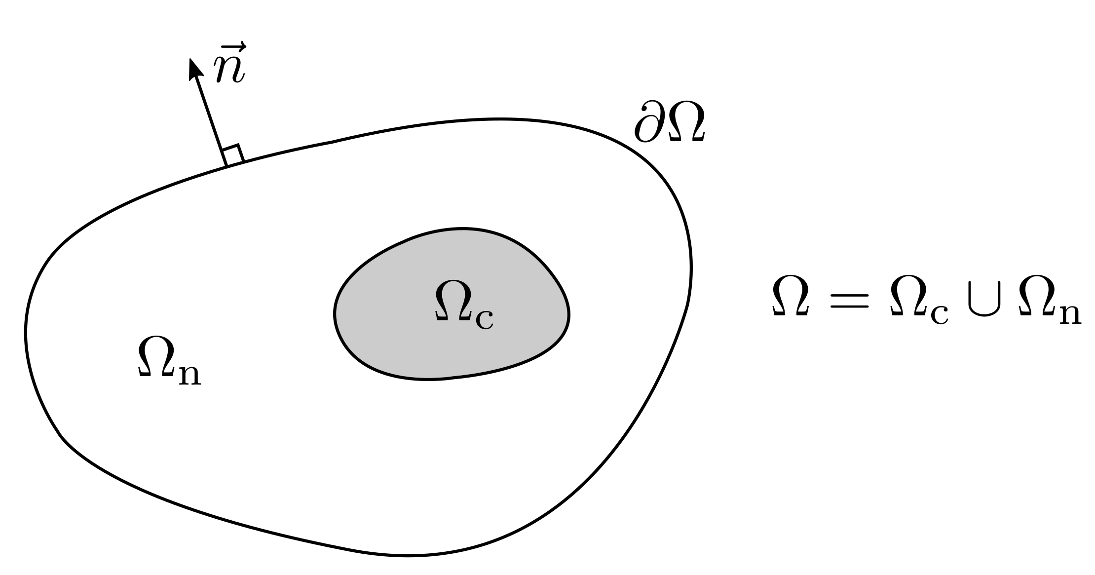
Using the non-gauged magnetic vector potential in -formulation, the governing MQS boundary value problem for the computational domain , see Fig. 1, reads
| (2) |
where is the nonlinear reluctivity, typically dependent on , is the electrical conductivity and is current density. The corresponding variational formulation of (2) reads: find such that
| (3) |
holds true for all curl-conforming edge element test functions .
2.1 Spatial discretization
The vector potential is approximated by a finite set of edge elements:
| (4) |
where and denotes the number degrees of freedom (DOF). According to the Galerkin scheme the test functions are taken from the same basis as . Coefficients assigned to the conductive area are stored in vector , likewise vector holds the coefficients in the nonconducting area , see Fig. 1. It follows the DAE system
| (5) |
where is the positive-definite and symmetric conductivity matrix, is the time dependent curl-curl matrix in the conductive region and is the constant curl-curl matrix in the non-conductive area. is the coupling matrix, which couples the DOF in the conductive area with neighboring DOF in the non-conductive area. The vector defined by the right-hand side (RHS) of the variational formulation (3) is only present to the non-conductive region . Due to the null-space of the discrete curl-curl operator , a vanishing weak divergence of in is crucial for the convergence of iterative solvers having a weak gauging property, e.g. the preconditioned conjugate gradient (PCG) method [6].
2.2 The explicit Euler time integration scheme
Replacing the time derivative in ODE system (9) by the forward discrete difference yields to the explicit Euler scheme. The solution for the -th time step reads
| (10) |
where is the time step size. The maximum stable time step size is determined by
| (11) |
where is the maximum eigenvalue.
2.3 The Runge-Kutta-Chebyshev time integration method
Alternatively, the system of ODEs (9) can be integrated explicitly in time by using the RKC method with a number of stages . In order to compute the -th time step the stages have the form
| (12) |
with . All coefficients appearing in the RKC scheme (12) are given analytically in [5] for an arbitrary number of stages . Let be the Chebyshev polynomial of the first kind and degree . For the coefficients are
| (13) |
with
| (14) |
and
| (15) |
The condition for absolute stability is given by
| (16) |
Unlike the stability criterion (11) of the explicit Euler scheme, the maximum stable time increment increases quadratically in the number of stages .
3 Numerical Case Study
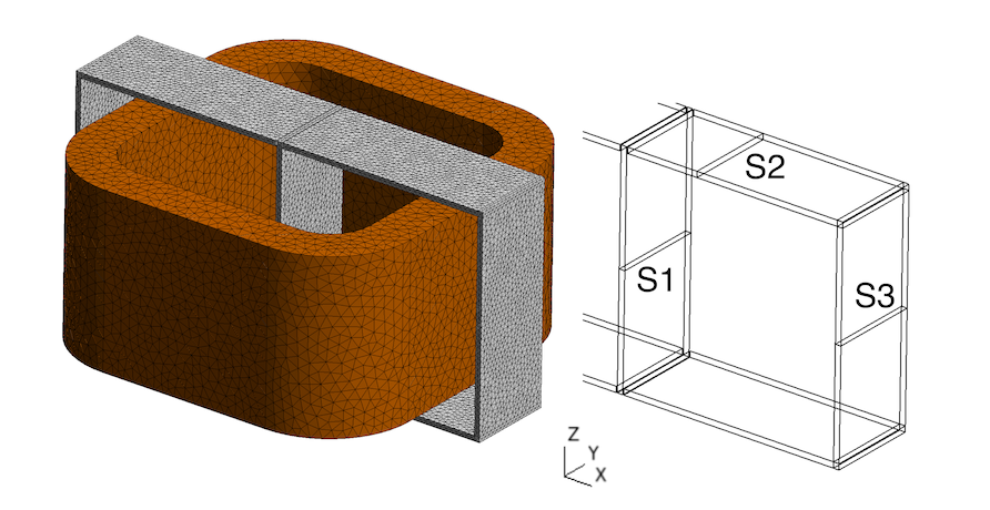
The case study in order to validate the formulations above is the TEAM 10 benchmark problem presented in [7]. It contains symmetrically placed steel plates around a coil, see Fig. 2. At the junction from the center plate to the left and right canal exists air gaps of . Furthermore, the conductive steel plates have a nonlinear B-H-characteristic. The coil has 162 turns and is excited by a transient current
| (17) |
Since the coil is modeled as a stranded conductor, the source current density appearing on the RHS of (2) is described as , where is the spatial current distribution. Is is computed using an electric vector potential formulation presented in [8].
In order to evaluate the matrix-vector product with the pseudo-inverse of the matrix in the RHS of ODE (9), a parallel PCG method with Jacobi preconditioner is applied. Since the matrix has full rank, the corresponding system of equations can be solved using a parallel direct solver. The evaluation of the vector potential in the conductive region is independent of the vector potential in the non-conductive region. Thus, the computation of according to equation (8) can be considered as a post-processing step. Furthermore, the matrix vector product is essentially a linear magneto-static problem in the non-conductive area. Thus, it is computed only once with and scaled with by evaluating the canonical RHS at time .
Since is evaluated in each time step at least once, the repetitive evaluation of the pseudo-inverse forms a multiple right-hand side problem, [3]. Therefore, the proper orthogonal decomposition (POD) is used in order to generate improved initial vectors for the PCG method.
3.1 Update strategy of the time dependent curl-curl matrix
The nonlinear reluctivity involves an update of the curl-curl matrix . Due to explicit time integration the curl-curl matrix is evaluated for past instances of the vector potential . Hence, a linearization scheme is avoided. However, the Runge-Kutta stages (12) still require multiple evaluations of per time step which are costly. This approach may therefore become inefficient since the maximal time step size , i.e. (11) and (16), does not reflect the dynamics of the solution. We suggest to bypass evaluations of the nonlinearity material curve.
As proposed in [4] the matrix is kept constant for several time steps as long as
| (18) |
holds true for a given tolerance , where is the latest solution and denotes the solution at the latest matrix update. In this case study the matrix is updated if exceeds %.
3.2 Numerical results
The FEM simulations according to the formulation above are executed on a tetrahedral mesh with about elements. To show convergence for a higher finite element (FE) order, the steel plates of the dimension , see Fig. 2, are coarsely discretized by an edge length of , the short side of the steel plates. The first order finite element dicretization contains about DOF, whereas the second order discretization results in about mio. DOF on the same mesh.
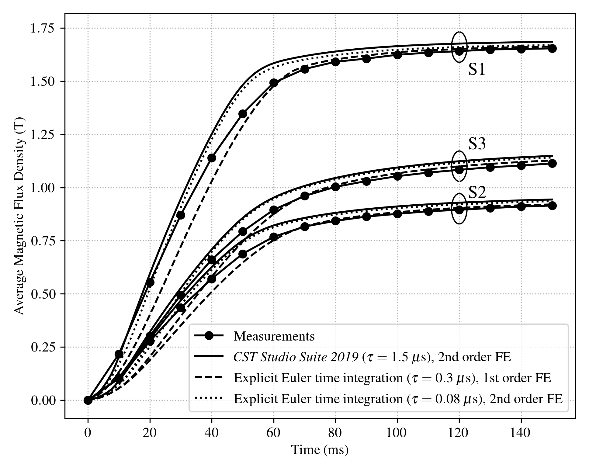
The numerical results using the explicit Euler scheme in comparison to measurements from [7] are depicted in Fig. 3. The quantity under test is the average magnetic flux density evaluated on the cross sections of the steel plates S1-S3, see Fig. 2. Both, for first and second order finite element solutions a good agreement with the measurements is noticeable when the magnetic flux saturates. In the time range a more significant deviation between the lowest order finite element simulation and the measurements is visible. In order to analyse this behavior a second order FEM simulation using the commercial CST Studio Suite 2019 software [9] is executed. This involves a different tetrahedral mesh of about elements where the short side of the steel plates have a finer discretization with four layers of elements. In Fig. 3 the second order finite element solution with the explicit scheme coincides well with the solution obtained from the CST Studio Suite 2019 software, thus it is taken as reference solution for further investigations.
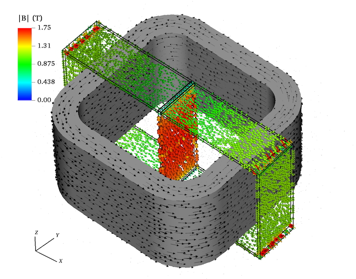
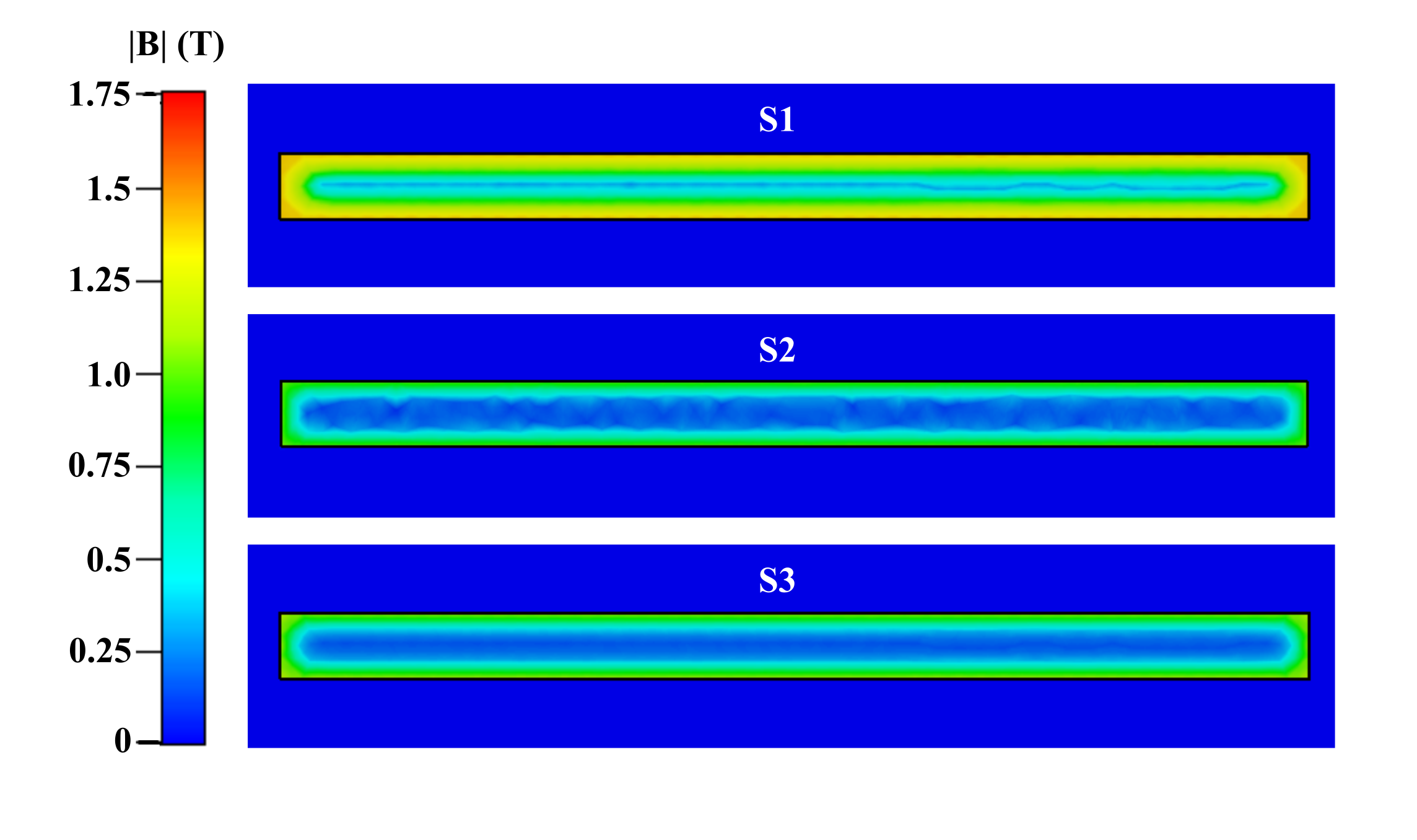
The deviations of the first order finite element solution to the reference solution is explained by a not sufficient spatial resolution of the skin effect. In this case study the strongest skin effect occurs at time , see Fig. 4. The relative error of the explicit Euler solution using second order finite elements is less than , see TABLE 1. Hence, the given mesh resolves the skin effect sufficiently with respect to the error by using second order finite element discretization. However, when the magnetic flux saturates less eddy currents are induced. Hence, the magnetic flux is approximately homogeneous and the coarse spatial discretization by using first order finite elements less affects the numerical error, which is at time . Fig. 5 shows the homogenous magnetic flux density in saturation as second order finite element solution, where the relative error is less than .
3.3 Performance study of the Runge-Kutta-Chebyshev method versus the explicit Euler scheme
A sufficient spatial discretization is crucial to resolve effects caused by induction as are the eddy currents and the skin effect. Due to the stability criterion (11) of the explicit Euler scheme, the time step size decreases quadratically by refining the spatial discretization. The RKC method provides a possibility to compensate the decrease of the maximum stable time increment by choosing a corresponding number of stages , see equation (16).
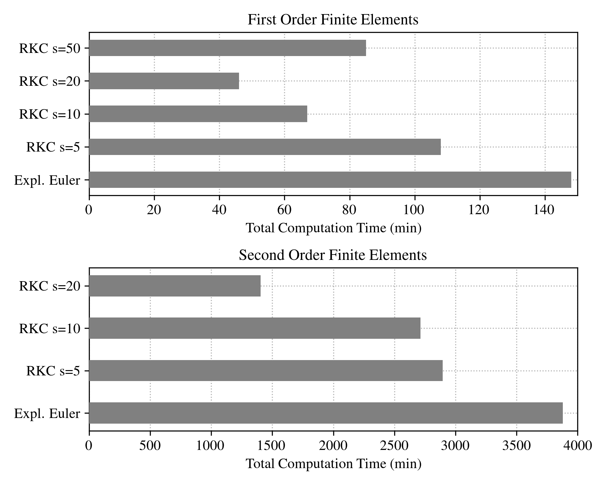
Within the Runge-Kutta stages (12), where the canonical RHS is evaluated at different time points , and , the time dependent curl-curl matrix is kept constant without regarding the update strategy described in section 3.1. The criterion (18) is only evaluated after a full time step.
Fig. 6 shows the total computation time of the RKC method in comparison with the explicit Euler scheme for first and second order finite elements. As expected, in both cases the explicit Euler scheme features the longest computation times. Employing the RKC method, the total simulation time consumption is diminished significantly for a higher number of stages . However, has to be chosen with care as larger time step sizes can trigger the update criterion (18) after each time step, which compromises the overall performance. For this reason, the RKC method with requires longer computation times than the RKC method with in the first order finite element setting.
| Time Integration Scheme | First Order FE | Second Order FE |
|---|---|---|
| Expl. Euler | ||
| RKC | ||
| RKC | ||
| RKC | ||
The error of all explicit methods with respect to the reference solution is approximately the same and is mainly given by the error in space. The deviation in the magnetic flux density is about and for first and second order finite elements, respectively, see TABLE 1.
All computations are executed with 20 parallel MPI processes on a workstation with an Intel Xeon E5 processor. The C++ library MFEM [10] is involved for obtaining the finite element operators, the library PETSc [11] provides the parallel PCG solver and the POD method as well as parallel direct solver.
4 Conclusion
For transient nonlinear magneto-quasistatic field simulations, in this paper a magnetic vector potential formulation was discretized using the finite element method of first and second polynomial order and the resulting system of DAEs was transformed into an ODE system employing a generalized Schur complement. This system of ODEs was integrated in time by the explicit Euler scheme and an explicit multistage Runge-Kutta-Chebyshev formulation of higher order, respectively.
Resolving eddy currents and the skin effect requires a suitably chosen fine spatial discretization. Since the maximum stable time step size of the explicit Euler scheme decreased quadratically for linear mesh refinements, the computation time was increased significantly. To compensate this effect of a diminished time step size, the RKC method was employed, where the maximum stable time step increase quadratically with the number of stages. The RKC method revealed a significant gain of performance over the explicit Euler scheme. The numerical tests showed that the performance of the RKC method is yet limited by the update strategy of the magnetic field dependent curl-curl matrix.
5 Acknowledgement
This work was supported by the Deutsche Forschungsgemeinschaft (DFG) under grant CL143/11-2 and SCHO1562/1-2. The work of S. Schöps was supported by the Excellence Initiative of the German Federal and State Governments and the Graduate School of Computational Engineering, Technical University of Darmstadt.
References
- [1] E. Hairer, G. Wanner, ”Solving Ordinary Differential Equations II”, 2nd ed. Berlin, Germany, Springer, 1996.
- [2] M. Clemens, S. Schöps, H. De Gersem, A. Bartel, ”Decomposition and regularization of nonlinear anisotropic curl-curl DAEs”, COMPEL-Int. J. Comput. Math. Elect. Electron. Eng., vol. 30, No. 6, pp. 1701-1714, 2011.
- [3] J. Dutiné, M. Clemens, S. Schöps, ”Multiple Right-Hand Side Techniques in Semi-Explicit Time Integration Methods for Transient Eddy Current Problems”, IEEE Trans. Magn., vol. 53, No. 6, Jun. 2017.
- [4] J. Dutiné, M. Clemens, S. Schöps, ”Explicit time integration of eddy current problems using a selective matrix update strategy”, COMPEL-Int. J. Comput. Math. Elect. Electron. Eng., vol. 36, No. 5, 2017.
- [5] B. P. Sommeijer, L. F. Shampine, J. G. Verwer, ”RKC: An explicit solver for parabolic PDEs”, Elsevier Journal of Computational and Applied Mathematics, vol. 88, pp. 315-326, 1997.
- [6] M. Clemens and T. Weiland, ”Transient eddy-current calculation with the FI-method”, IEEE Trans. Magn., vol. 35, no. 3, pp. 1163-1166, May 1999.
- [7] T. Nakata, K. Fujiwara, ”Results for benchmark problem 10 (steel plates arround a coil)”, COMPEL-Int. J. Comput. Math. Elect. Electron. Eng., vol. 9, No. 3, pp. 181.190, Mar. 1990.
- [8] Z. Ren, ”Influence of the R.H.S. on the Convergence Behaviour of the Curl-Curl Equation”, IEEE Trans. Magn., vol. 32, No. 3, May 1996.
- [9] Dassault Systems, CST Studio Suite 2019
- [10] T. Kolev, V. Dobrev, ”Modular Finite Element Methods (MFEM)” Computer software, June 21, 2010, https://github.com/mfem/mfem, doi:10.11578/dc.20171025.1248.
- [11] S. Balay, S. Abhyankar et al., ”Portable, Extensible Toolkit for Scientific Computation (PETSc)” Computer software, 2019, https://www.mcs.anl.gov/petsc