Large angle precession of magnetization maintained by a microwave voltage
Abstract
Effects of a microwave voltage on magnetization precession are analyzed based on a macrospin model. The microwave voltage induces the oscillating anisotropy field through the voltage controlled magnetic anisotropy (VCMA) effect, and then stimulates the magnetization. The large angle precession is maintained if the magnetization synchronizes with the microwave voltage. The effective equations of motion of the magnetization with an oscillating anisotropy field are derived, and the mechanism of the synchronization is clarified by analyzing the derived equations of motion. The conditions of the angular frequency detuning and the amplitude of the oscillating anisotropy field for synchronization are obtained. The results are useful for development of the VCMA-based energy-efficient spintronics devices using magnetization precession such as a VCMA-based magnetoresistive random access memory and a nano-scale microwave magnetic field generator.
I introduction
Magnetic anisotropy (MA) is a key property of a ferromagnet, which stabilizes the direction of magnetization even at room temperature [1, 2]. In a magnetoresistive random access memory (MRAM) the information is stored as the direction of magnetization, e.g. up or down. The height of the energy barrier between the up and down states is proportional to the MA constant, and the retention time of the information is an exponential increasing function of the MA constant [3]. The current standard writing scheme of MRAM utilizes the spin transfer torque (STT) [4, 5, 6] because of low power consumption and high integration density compared with the magnetic field switching. The STT acts as the negative damping torque and excites the magnetization over the energy barrier.
The discovery of voltage controlled magnetic anisotropy (VCMA) effect [7, 8, 9, 10, 11, 12, 13] provides a more energy-efficient writing scheme of MRAM. In the VCMA-based switching [14, 15, 16, 17, 18, 19, 20, 21, 22, 23, 24], application of the voltage to the MRAM cell eliminates the MA of the free layer (FL) and induces the precession of magnetization around the external magnetic field. The switching completes if the voltage is turned off at a half period of precession. The power consumption of the VCMA-based switching is much smaller than that of the STT-based switching because of little Joule heating [16, 17].
Parametric excitation (PE) is a nonlinear phenomenon induced by periodic modulation of a parameter in equations of motion and, which has been studied in many areas of physics and engineering [25]. In magnetic materials PE of magnetization is induced by applying a microwave field [26, 27, 28, 29, 30, 31, 32, 33, 34, 35, 36], microwave current [37, 38, 39], or microwave voltage [40, 41, 42, 43, 44]. The PE of the spin waves by microwave voltage in ferromagnetic films [40, 41, 42] attracts much attention as a key element of low power consumption magnonic devices [45].
Very recently Yamamoto et al. studied the effect of PE on the VCMA-based switching in an MRAM cell and found that the oscillation amplitude of the switching probability does not decay if the magnetization precesses in synchronization with the applied oscillating voltage [44]. They also performed the numerical simulations based on the macrospin model and reproduced the experimental results very well. Although the results are qualitatively and intuitively explained by the concept of PE, more detailed theoretical analysis on the mechanism as well as the conditions for the PE in this system is necessary for practical applications. Since the experimental situation is quite different from the PE of spin waves in ferromagnetic films, the theory developed by Verba et al. [40, 41, 42] is not directly applicable for the analysis of the results in Ref. [44].
In this paper, we analyze the effects of a microwave voltage on magnetization precession using the macrospin model following the standard analysis of PE [25]. It is shown that the large angle precession is maintained if the magnetization synchronizes with the microwave voltage. The mechanism of the synchronization is clarified, and the conditions of parameters for synchronization are obtained by analyzing the effective equations of motion of the magnetization under the microwave voltage.
The results are useful for reducing the write error rate of the VCMA-based MRAM by using a microwave voltage pulse. The large angle precession of magnetization maintained by a microwave voltage can be applied as a low-power nano-scale microwave magnetic field generator.
II model and method
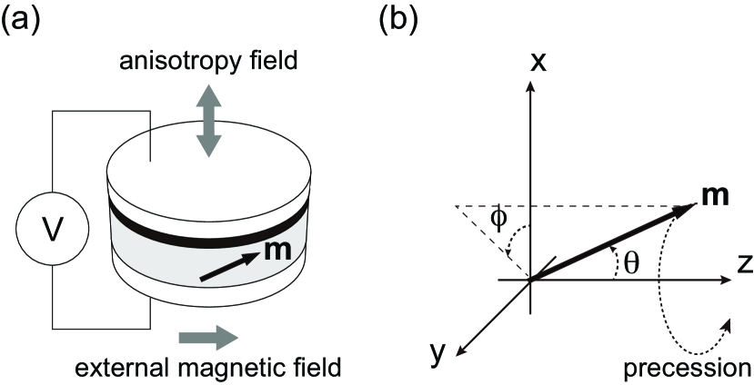
The system we consider is schematically shown in Fig. 1(a). The FL of a VCMA-based MRAM with perpendicular MA is shown in gray. Application of a voltage, , modifies the electron state at the interface between the FL and the insulating layer shown in black and changes the MA of the FL through the VCMA effect. The white cylinders represent the other layers such as the reference layer and electrodes. The definition of the coordinate system is shown in Fig. 1(b). In terms of the polar angle, , and the azimuthal angle, , the magnetization unit vector, , is expressed as = (,,) = (,,). The external magnetic field, , is applied to the positive direction and the perpendicular anisotropy field is parallel to the axis. The voltage is assumed to be the sum of the static and oscillating components expressed as . The static component, , is assumed to be large enough to eliminate the static MA of the FL. The oscillating component, , generates the oscillating anisotropy field and stimulates the magnetization.
In order to simplify the notation, the dimensionless forms of the magnetic field and time are introduced. The external field, , is taken as the unit of the magnetic field. The unit of time is set , where is the Gilbert damping constant and is the gyromagnetic ratio.
The oscillating anisotropy field induced by is given by
| (1) |
where is the amplitude of the oscillating anisotropy field, and and are the angular frequency of and time in the dimensionless unit, respectively. The dynamics of is obtained by solving the following Landau-Lifshitz-Gilbert (LLG) equation,
| (2) | ||||
| (3) |
where the dot represents the derivative in terms of . The values of and are assumed to be much smaller than unity. For numerical simulations and exemplification of the analytical results we assume and unless otherwise mentioned. In numerical simulations the 4th order Runge-Kutta method is employed to solve the LLG equation. Before application of the voltage the magnetization is aligned perpendicular to the plane because the FL has a static perpendicular MA. The initial state is assumed to be , i.e. and .
III Results and Discussions
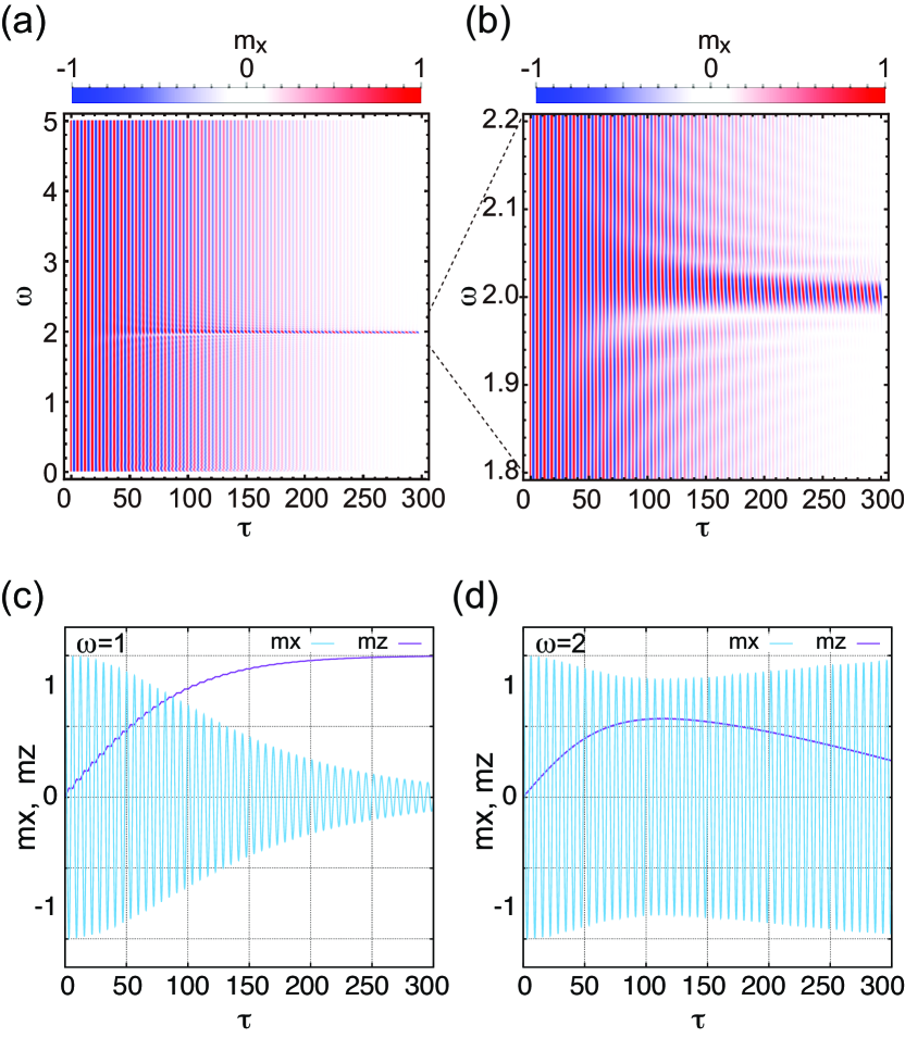
Figure 2(a) is the color density plot of on - plane, which can be observed owing to the magnetoresistance effect. The large amplitude of oscillation is maintained around twice the natural angular frequency of precession, i.e. . In Ref. 44, the similar plots were obtained for the switching probabilities. The enlarged view for is shown in Fig. 2(b). The region of angular frequency where the large amplitude of oscillation is maintained is . Outside of this synchronization region the oscillation amplitude shows a monotonic decay.
The dynamics of and at is plotted in Fig. 2(c). increases with increase of and approaches to unity. shows the damped oscillation with a period of . These results agree well with the exact solutions for [2], which implies that the with has little effect on the magnetization dynamics.
The same plot at are shown in Fig. 2(d). Contrary to the results at , the oscillation amplitude does not show a monotonic decay. Although the oscillation amplitude decays for , it takes the minimum value at and then increases with increase of . The period of oscillation is , i.e. oscillates with the natural angular frequency of unity instead of the angular frequency of , . The fact that the precession amplitude of is strongly enhanced by the external periodic force with twice the natural angular frequency implies that this phenomena is closely related to the parametric excitation [26, 27, 28, 30, 31, 32, 33, 38, Chen2017b].
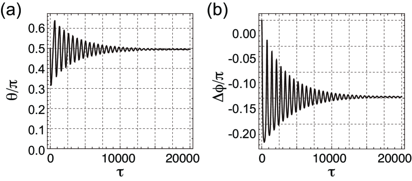
Figure 3(a) shows the dynamics of the polar angle, , at for a long time duration of . Figure 3(b) is the same plot for the phase shift from the free precession at the angular frequency of , which is defined as
| (4) |
The polar angle is a measure of the oscillation amplitude because . The azimuthal angle, , represents the oscillation phase, and the phase shift, , is closely related to the energy absorption. The polar angle shows a slow oscillation with a period much longer than and converges to about for large . The phase shift also shows the slow oscillation with the same period as the polar angle and converges to about for large .
The equation of motion for the slow dynamics of the polar angle is derived as follows. Since both and are assumed to be much smaller than unity, the terms with can be neglected in the LLG equation. Then Eq. (II) becomes
| (5) |
The second term on the right hand side depends on as , where comes from , and is the projection coefficient of the anisotropy field torque to the direction of . Since , should be twice the angular frequency of magnetization precession to realize synchronization.
Substituting into Eq. (5) and applying the trigonometric identities we obtain
| (6) |
Since we are interested in the slow dynamics of and we average out the fast oscillating term with . Finally the equation of motion for the slow dynamics of is obtained as
| (7) |
Introducing the effective damping coefficient defined as
| (8) |
Eq. (7) is expressed as , which is the same form as Eq. (II) with . Assuming that and in the limit of , the convergence value of the phase shift, , should be adjusted to satisfy . There are two kinds of solutions for this equation. One is
| (9) |
and the other is
| (10) |
For the parameters we assumed, i.e. and , which is identical to the numerical results shown in Fig. 3(b).
The equation of motion for the slow dynamics of is obtained in a similar manner. Substituting into Eq. (3), neglecting the term with , and averaging out the fast oscillating term, we obtain
| (11) |
Equation (11) is reduced to at . Assuming that , i.e. , the sign of is determined by the sign of . increases (decreases) with increase of if (.
To understand the mechanism of the synchronization we analyze the dynamics of , , and in the first two and a half period of oscillation. Figure 4 shows the dynamics of (top), (middle), and (bottom) at for . The horizontal dashed lines in the top, middle, and bottom panels represent the values of , , and zero, respectively. The vertical dotted lines represent the values of at which takes the convergence value of .
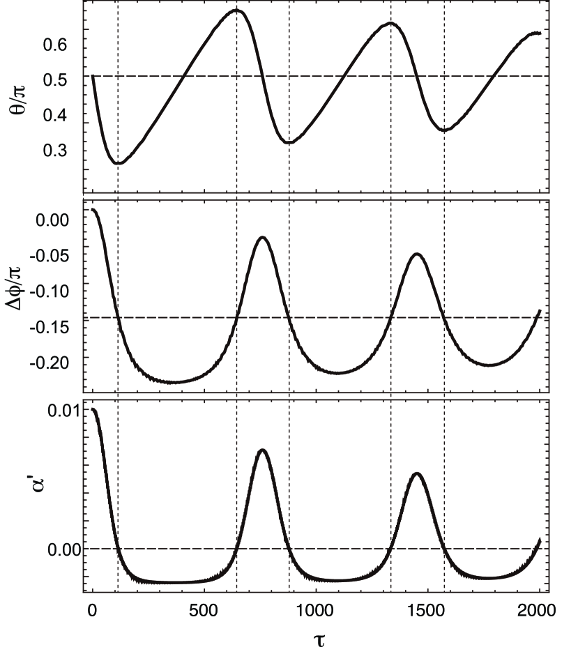
At the beginning of the dynamics, decreases with increase of because (0). also decreases with increase of because . The decrease of induces the reduction of following Eq. (8). When crosses the horizontal dashed line, i.e. , takes the minimum value and then starts to increase with increase of because becomes negative. However and decrease with increase of until exceeds . At , crosses the horizontal dashed line at . Then both and take the minimum values and start to increase with increase of . Repeating the above procedure , , and oscillate with the same period as each other and converge to the value of , , and zero, respectively.
Let us move on to the analysis of the effect of angular frequency detuning on synchronization. The angular frequency detuning is defined as the difference between the angular frequency of and twice the natural angular frequency of magnetization precession, i.e. . As shown in the Fig. 2(b) synchronizes with the within the range of at . The synchronization region of in the limit of is obtained as follows. Substituting into Eq. (11) we obtain
| (12) |
Assuming that and the convergence value of is obtained by solving
| (13) |
as
| (14) |
which is valid for because the convergence value of should satisfy .
The convergence value of for the case with is obtained in a similar manner as
| (15) |
which is valid for , At , and both and are the valid solutions. Since it might be difficult to achieve a stable oscillation.
The general expressions of the convergence values of and are summarized as follows
| (16) | ||||
| (17) |
The synchronization region of is obtained by requiring as
| (18) |
The synchronization condition of is obtained in a similar manner as
| (19) |
Taking the limit of the critical value of is obtained as 4.
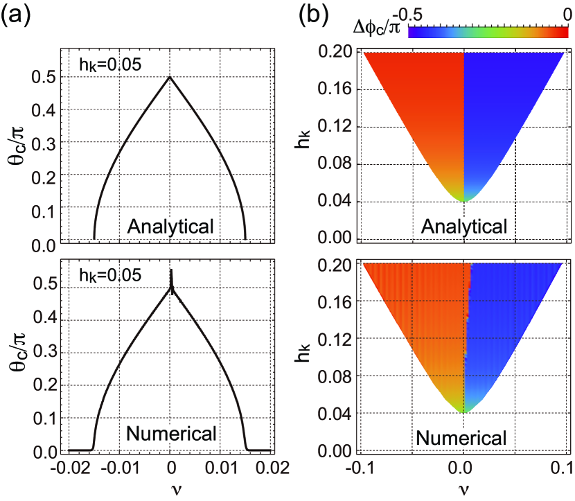
Figure 5(a) shows dependence of . The analytical results of Eq. (17) is shown in the top panel. The numerical results obtained by solving Eqs. (II) and (3) for 20000 are shown in the bottom panel. Although the analytical results are almost identical to the numerical ones, the small sharp peak appears in the vicinity of in the numerical results. At this value of the numerical simulations do not converge even at .
Figure 5(b) is the color density plot of the phase shift in the synchronization region on the - plane. The analytical results of Eqs. (16) and (19) are shown in the top panel. The numerical results obtained by solving Eqs. (II) and (3) for 20000 are shown in the bottom panel, where the synchronization region is defined to satisfy 0.01 at . In both panels the red and blue tones represent and , respectively. The analytical results are almost identical to the numerical ones. However the boundary between and in the numerical results shifts slightly toward larger from the analytical boundary at . This small deviation is caused by the terms with which we neglect in the analytical calculations.
IV Summary
In summary, the effects of microwave voltage on the magnetization dynamics in the FL of a VCMA-based MRAM is theoretically analyzed. It is shown that the large angle precession of magnetization is maintained if the angular frequency of the microwave voltage is about twice the natural angular frequency of the precession. The effective equations of motion for the slow dynamics of the polar angle and the phase shift are derived. The mechanism of the synchronization is explained by analyzing the slow dynamics of the polar angle, phase shift, and effective damping coefficient. The phase shift is automatically adjusted to eliminate the effective damping. The convergence value of the phase shift strongly depends on the sign of the angular frequency detuning. The synchronization conditions of the angular frequency detuning and the amplitude of the oscillating anisotropy field are obtained. The critical value of the amplitude of the oscillating anisotropy field is proportional to the Gilbert damping constant. The results are useful for development of the VCMA-based energy-efficient spintronics devices using magnetization precession such as a VCMA-based MRAM and a nano-scale microwave magnetic field generator.
Acknowledgements.
We acknowledge T. Nozaki and T. Yamamoto for useful discussions. This work was partly supported by JSPS KAKENHI Grant Numbers JP19K05259 and JP19H01108.References
- Chikazumi [1997] S. Chikazumi, Physics of Ferromagnetism (Oxford : Clarendon press, 1997).
- Landau and Lifshits [1960] L. D. Landau and E. M. Lifshits, Electrodynamics of continuous media (Pergamon Press, Oxford; New York, 1960).
- Brown [1963] W. F. Brown, Thermal Fluctuations of a Single-Domain Particle, Physical Review 130, 1677 (1963) .
- Slonczewski [1996] J. C. Slonczewski, Current-driven excitation of magnetic multilayers, Journal of Magnetism and Magnetic Materials 159, L1 (1996).
- Berger [1996] L. Berger, Emission of spin waves by a magnetic multilayer traversed by a current, Physical Review B 54, 9353 (1996).
- Stiles and Miltat [2006] M. D. Stiles and J. Miltat, Spin-transfer torque and dynamics, in Topics in Applied Physics, Vol. 101 (Springer Berlin Heidelberg, 2006) pp. 225–308.
- Weisheit et al. [2007] M. Weisheit, S. Fahler, A. Marty, Y. Souche, C. Poinsignon, and D. Givord, Electric Field-Induced Modification of Magnetism in Thin-Film Ferromagnets, Science 315, 349 (2007).
- Duan et al. [2008] C.-G. Duan, J. P. Velev, R. F. Sabirianov, Z. Zhu, J. Chu, S. S. Jaswal, and E. Y. Tsymbal, Surface Magnetoelectric Effect in Ferromagnetic Metal Films, Physical Review Letters 101, 137201 (2008) .
- Tsujikawa and Oda [2009] M. Tsujikawa and T. Oda, Finite Electric Field Effects in the Large Perpendicular Magnetic Anisotropy Surface Pt/Fe/Pt(001): A First-Principles Study, Physical Review Letters 102, 247203 (2009).
- Nakamura et al. [2009] K. Nakamura, R. Shimabukuro, Y. Fujiwara, T. Akiyama, T. Ito, and A. J. Freeman, Giant modification of the magnetocrystalline anisotropy in transition-metal monolayers by an external electric field, Physical Review Letters 102, 187201 (2009).
- Maruyama et al. [2009] T. Maruyama, Y. Shiota, T. Nozaki, K. Ohta, N. Toda, M. Mizuguchi, A. A. Tulapurkar, T. Shinjo, M. Shiraishi, S. Mizukami, Y. Ando, and Y. Suzuki, Large voltage-induced magnetic anisotropy change in a few atomic layers of iron, Nature Nanotechnology 4, 158 (2009).
- Nozaki et al. [2010] T. Nozaki, Y. Shiota, M. Shiraishi, T. Shinjo, and Y. Suzuki, Voltage-induced perpendicular magnetic anisotropy change in magnetic tunnel junctions, Applied Physics Letters 96, 3 (2010).
- Endo et al. [2010] M. Endo, S. Kanai, S. Ikeda, F. Matsukura, and H. Ohno, Electric-field effects on thickness dependent magnetic anisotropy of sputtered MgO/Co40Fe40B20/Ta structures, Applied Physics Letters 96, 3 (2010).
- Shiota et al. [2012] Y. Shiota, T. Nozaki, F. Bonell, S. Murakami, T. Shinjo, and Y. Suzuki, Induction of coherent magnetization switching in a few atomic layers of FeCo using voltage pulses, Nature Materials 11, 39 (2012).
- Kanai et al. [2012] S. Kanai, M. Yamanouchi, S. Ikeda, Y. Nakatani, F. Matsukura, and H. Ohno, Electric field-induced magnetization reversal in a perpendicular-anisotropy CoFeB-MgO magnetic tunnel junction, Applied Physics Letters 101, 122403 (2012).
- Grezes et al. [2016] C. Grezes, F. Ebrahimi, J. G. Alzate, X. Cai, J. A. Katine, J. Langer, B. Ocker, P. Khalili Amiri, and K. L. Wang, Ultra-low switching energy and scaling in electric-field-controlled nanoscale magnetic tunnel junctions with high resistance-area product, Applied Physics Letters 108, 3 (2016).
- Kanai et al. [2016] S. Kanai, F. Matsukura, and H. Ohno, Electric-field-induced magnetization switching in CoFeB/MgO magnetic tunnel junctions with high junction resistance, Applied Physics Letters 108, 192406 (2016).
- Matsumoto et al. [2018] R. Matsumoto, T. Nozaki, S. Yuasa, and H. Imamura, Voltage-Induced Precessional Switching at Zero-Bias Magnetic Field in a Conically Magnetized Free Layer, Physical Review Applied 9, 014026 (2018).
- Yamamoto et al. [2018] T. Yamamoto, T. Nozaki, Y. Shiota, H. Imamura, S. Tamaru, K. Yakushiji, H. Kubota, A. Fukushima, Y. Suzuki, and S. Yuasa, Thermally Induced Precession-Orbit Transition of Magnetization in Voltage-Driven Magnetization Switching, Physical Review Applied 10, 024004 (2018).
- Imamura and Matsumoto [2019] H. Imamura and R. Matsumoto, Impact of Spin-Transfer Torque on the Write-Error Rate of a Voltage-Torque-Based Magnetoresistive Random-Access Memory, Physical Review Applied 11, 064019 (2019).
- Matsumoto et al. [2019] R. Matsumoto, T. Sato, and H. Imamura, Voltage-induced switching with long tolerance of voltage-pulse duration in a perpendicularly magnetized free layer, Applied Physics Express 12, 053003 (2019).
- Yamamoto et al. [2019] T. Yamamoto, T. Nozaki, H. Imamura, Y. Shiota, T. Ikeura, S. Tamaru, K. Yakushiji, H. Kubota, A. Fukushima, Y. Suzuki, and S. Yuasa, Write-Error Reduction of Voltage-Torque-Driven Magnetization Switching by a Controlled Voltage Pulse, Physical Review Applied 11, 014013 (2019).
- Yamamoto et al. [2020a] T. Yamamoto, T. Nozaki, H. Imamura, S. Tamaru, K. Yakushiji, H. Kubota, A. Fukushima, Y. Suzuki, and S. Yuasa, Voltage-Driven Magnetization Switching Using Inverse-Bias Schemes, Physical Review Applied 13, 014045 (2020a).
- Matsumoto and Imamura [2020] R. Matsumoto and H. Imamura, Low-Power Switching of Magnetization Using Enhanced Magnetic Anisotropy with Application of a Short Voltage Pulse, Physical Review Applied 14, 021003 (2020).
- doi [2007] Parametrically Excited Systems, in Nonlinear Oscillations (John Wiley & Sons, Ltd, 2007) Chap. 5, pp. 258–364.
- Bloembergen and Damon [1952] N. Bloembergen and R. W. Damon, Relaxation Effects in Ferromagnetic Resonance, Physical Review 85, 699 (1952).
- Bloembergen and Wang [1954] N. Bloembergen and S. Wang, Relaxation Effects in Para - and Ferromagnetic Resonance, Physical Review 93, 72 (1954).
- Anderson and Suhl [1955] P. W. Anderson and H. Suhl, Instability in the Motion of Ferromagnets at High Microwave Power Levels, Physical Review 100, 1788 (1955).
- Urazhdin et al. [2010a] S. Urazhdin, P. Tabor, V. Tiberkevich, and A. Slavin, Fractional Synchronization of Spin-Torque Nano-Oscillators, Physical Review Letters 105, 104101 (2010a).
- Urazhdin et al. [2010b] S. Urazhdin, V. Tiberkevich, and A. Slavin, Parametric Excitation of a Magnetic Nanocontact by a Microwave Field, Physical Review Letters 105, 237204 (2010b).
- Ulrichs et al. [2011] H. Ulrichs, V. E. Demidov, S. O. Demokritov, and S. Urazhdin, Parametric excitation of eigenmodes in microscopic magnetic dots, Physical Review B 84, 094401 (2011).
- Martin et al. [2011] S. Y. Martin, N. de Mestier, C. Thirion, C. Hoarau, Y. Conraux, C. Baraduc, and B. Diény, Parametric oscillator based on nonlinear vortex dynamics in low-resistance magnetic tunnel junctions, Physical Review B 84, 144434 (2011) .
- Edwards et al. [2012] E. R. J. Edwards, H. Ulrichs, V. E. Demidov, S. O. Demokritov, and S. Urazhdin, Parametric excitation of magnetization oscillations controlled by pure spin current, Physical Review B 86, 134420 (2012).
- Zhu et al. [2008] J.-G. Zhu, X. Zhu, and Y. Tang, Microwave Assisted Magnetic Recording, IEEE Transactions on Magnetics 44, 125 (2008).
- Lu et al. [2013] L. Lu, M. Wu, M. Mallary, G. Bertero, K. Srinivasan, R. Acharya, H. Schultheiß, and A. Hoffmann, Observation of microwave-assisted magnetization reversal in perpendicular recording media, Applied Physics Letters 103, 2 (2013).
- Zhou et al. [2017] W. Zhou, T. Yamaji, T. Seki, H. Imamura, and K. Takanashi, Resonant magnetization switching conditions of an exchange-coupled bilayer under spin wave excitation, Applied Physics Letters 110, 082401 (2017).
- Cui et al. [2008] Y.-T. Cui, J. C. Sankey, C. Wang, K. V. Thadani, Z.-P. Li, R. A. Buhrman, and D. C. Ralph, Resonant spin-transfer-driven switching of magnetic devices assisted by microwave current pulses, Physical Review B 77, 214440 (2008).
- Dürrenfeld et al. [2014] P. Dürrenfeld, E. Iacocca, J. Åkerman, and P. K. Muduli, Parametric excitation in a magnetic tunnel junction-based spin torque oscillator, Applied Physics Letters 104, 052410 (2014).
- Montoya et al. [2019] E. A. Montoya, S. Perna, Y.-J. Chen, J. A. Katine, M. D’Aquino, C. Serpico, and I. N. Krivorotov, Magnetization reversal driven by low dimensional chaos in a nanoscale ferromagnet, Nature Communications 10, 543 (2019) .
- Verba et al. [2014] R. Verba, V. Tiberkevich, I. Krivorotov, and A. Slavin, Parametric Excitation of Spin Waves by Voltage-Controlled Magnetic Anisotropy, Physical Review Applied 1, 044006 (2014).
- Verba et al. [2016] R. Verba, M. Carpentieri, G. Finocchio, V. Tiberkevich, and A. Slavin, Excitation of propagating spin waves in ferromagnetic nanowires by microwave voltage-controlled magnetic anisotropy, Scientific Reports 6, 25018 (2016).
- Verba et al. [2017] R. Verba, M. Carpentieri, G. Finocchio, V. Tiberkevich, and A. Slavin, Excitation of Spin Waves in an In-Plane-Magnetized Ferromagnetic Nanowire Using Voltage-Controlled Magnetic Anisotropy, Physical Review Applied 7, 064023 (2017).
- Chen et al. [2017] Y.-J. Chen, H. K. Lee, R. Verba, J. A. Katine, I. Barsukov, V. Tiberkevich, J. Q. Xiao, A. N. Slavin, and I. N. Krivorotov, Parametric Resonance of Magnetization Excited by Electric Field, Nano Letters 17, 572 (2017).
- Yamamoto et al. [2020b] T. Yamamoto, T. Nozaki, H. Imamura, S. Tamaru, K. Yakushiji, H. Kubota, A. Fukushima, and S. Yuasa, Voltage-Driven Magnetization Switching Controlled by Microwave Electric Field Pumping, Nano Letters 20, 6012 (2020b).
- Rana and Otani [2019] B. Rana and Y. C. Otani, Towards magnonic devices based on voltage-controlled magnetic anisotropy, Communications Physics 2, 90 (2019).