Toward Impact-resilient Quadrotor Design, Collision Characterization and Recovery Control to Sustain Flight after Collisions
Abstract
Collision detection and recovery for aerial robots remain a challenge because of the limited space for sensors and local stability of the flight controller. We introduce a novel collision-resilient quadrotor that features a compliant arm design to enable free flight while allowing for one passive degree of freedom to absorb shocks. We further propose a novel collision detection and characterization method based on Hall sensors, as well as a new recovery control method to generate and track a smooth trajectory after a collision occurs. Experimental results demonstrate that the robot can detect and recover from high-speed collisions with various obstacles such as walls and poles. Moreover, it can survive collisions that are hard to detect with existing methods based on IMU data and contact models, for example, when colliding with unstructured surfaces, or being hit by a moving obstacle while hovering.
I Introduction
Unmanned aerial vehicles (UAVs) proliferate across applications [1]. Among UAVs, the quadrotor has become the standard of practice [2]. Advances in control of quadrotors [3, 4], allow them to perform tasks such as acrobatics [5], grasping [6], perching [7], carrying suspended payloads [8], and flying through narrow gaps [9, 10]. An integral part of UAV operation is collision avoidance. However, despite advances in integration of perception and planning for collision avoidance (e.g., [11, 12, 13]), quadrotors still remain vulnerable to collisions that may occur because of unreliable sensors or unpredictable disturbances [14]. The challenge becomes pronounced as quadrotors are tasked to operate in increasingly complex, cluttered and partially-known environments.
The thesis adopted is this work is that instead of completely avoiding collisions it may be beneficial to cope with them [15, 16, 17, 18]. In fact, sustaining flight after collision—a property that most existing works cannot guarantee [19]—may be crucial to deploy quadrotors in complex and cluttered environments. The capability to withstand and recover from collisions has been shown to benefit aerial robot navigation in partially-known environments [20, 21].
We introduce a novel actively resilient quadrotor (ARQ), which incorporates passive springs within its frame to absorb shocks and survive collisions. The quadrotor is equipped with Hall sensors to accurately and rapidly detect the location (in the robot’s frame) and intensity of a collision. To take advantage of the injected compliance and resulting resilience to collisions, we further develop a recovery controller that enables the quadrotor to sustain flight after active collision with walls, poles and unstructured obstacles, or after being passively collided by moving objects while hovering (Fig. 1).

The ARQ design successfully combines the advantages of two main strategies of existing collision-resilient robots (see Section II) by incorporating passive springs in the frame together with regular rigid protective cages to reduce harmful impacts; these protect the robot from impact speeds in excess of 5.9 m/s. Moreover, ARQ can sustain flight after collision with walls with the fastest speeds to date, and it can recover from active and passive collisions with different obstacles without any prior knowledge on collision models.
The contributions of this work are as follows:
-
•
We design, fabricate, and test a novel actively resilient quadrotor that incorporates compliance and sensors to withstand and detect collisions.
-
•
We propose a collision detection and characterization method based on Hall sensors.
-
•
We propose a recovery control method that generates and tracks a smooth trajectory after colliding.
-
•
We investigate our robot’s collision-resilient capabilities on collisions with walls, poles, unstructured surfaces, and passive collisions (i.e. being hit and free fall).
II Related Work
Collision-resilient UAVs are designed to survive crashes with obstacles with no irreversible structural damage [22]. So far, research in collision-resilient UAVs has taken two different, largely non-overlapping routes: (1) incorporating protective frames to reduce chances of catastrophic impact, and (2) utilizing sensors to detect and recover from collisions.
Approaches under the first case rely on mechanical design to offer passive protection to the UAV. Cages or protective structures are added to prevent damaging sensitive elements of the robot [20, 23, 24]. Other attempts involve the use of rotation to isolate effects of a collision on the robot [25], or exploit the added angular momentum to improve disturbance rejection [14]. Another way is to use bio-inspired strategies and soft materials to survive crashes [26, 22, 27]. However, careful mechanical design alone cannot help detect and characterize collisions, which is essential to sustain flight.
Works on sensor-based collision detection and characterization have mainly focused on using data from the inertial measurement unit (IMU). External wrench estimation [19], multiplicative extended Kalman filter (MEKF) [28] and fuzzy logic process (FLP) [29] have been found feasible to detect and characterize collisions with the onboard IMU, to assist recovery control. However, those methods rely on prior knowledge of collision dynamics or require data for training collision models, thereby limiting applicability for collision-resilient control. Further, IMUs are usually unable to distinguish collisions during aggressive flight and to detect static contacts, resulting in low accuracy in collision detection [30]. Position error between IMU data and ground truth from motion capture [20], and accelerometer data alone [21] can identify collisions; however, the methods cannot localize collisions, which is key to sustain flight.
The use of Hall sensors (as in here) has been used in the past to provide more accurate collision detection [30], albeit for a very different airframe with two rotors aligned vertically. However, and critically different from our work, [30] does not focus on collision recovery control. In addition, when compared to other works on design of resilient UAVs with collision detection, our work uniquely integrates physical compliance to reduce the detrimental impacts of collision.
III Hardware and Software Design of ARQ
The quadrotor is built based on off-the-shelf components and custom 3D-printed parts. To embrace collision and enable recovery, each arm of ARQ integrates a shock absorber and Hall sensor. The platform features custom nylon protective cages, a Pixhawk 4 Mini flight controller with the open-source PX4 autopilot firmware, an Odroid XU4 with the ROS environment as the companion computer, and an Arduino Nano for analog to digital conversion (Fig. 2).

III-A Electro-mechanical Hardware Prototyping
Key components of ARQ include its compliant arm design and the integration of Hall sensors to estimate deformations.
III-A1 Compliant Arm Design
Unlike existing resilient flying robots whose physical configurations are drastically changed after collision [27, 22], the configuration of ARQ remains the same before and after a collision. This property makes ARQ an appropriate platform to conduct complex tasks that require model-based control. To this end, our design uniquely retains rigidity when in free flight while allowing for one passive degree of freedom in the direction along each arm to absorb harmful impacts from collision.

The computer-aided design (CAD) assembly and main components of ARQ’s novel arm are shown in Fig. 3. The prismatic joint is built based on a solid brass 2-inch surface bolt. The bolt is covered by heat-shrinkable tubes to reduce the free space within the joint. The aluminum shock absorber is taken from 1/18 radio-control cars. An A1302 ratiometric linear Hall sensor is fixed on the prismatic joint to measure the magnetic intensity. The adapters connecting the prismatic joint and shock absorber are 3D-printed (Markforged Mark II, onyx material with carbon fiber add-in). The stiffness of the spring within the shock absorber is adjusted so that the length of the arm remains unchanged during free flight.
III-A2 Hall Sensor
The ability to detect and characterize collisions is critical to stabilize quadrotors and sustain flight. Existing collision-detection methods with IMUs require detailed modeling of the environment and obstacles [29], limiting application in unknown environments. In this work, we use Hall sensors for collision detection as in [30].
Hall sensors are commonly used to measure the magnitude of a magnetic field. The sensor’s output voltage is directly proportional to the magnetic field strength through it. In our prototype, A1302 ratiometric linear Hall sensors are fixed on the prismatic joints, coming in contact with the magnet when the length of a shock absorber reduces to its minimum. Despite the relatively short distance, the rotating motors were observed to have almost no effect on the Hall sensors’ readings. Experimental testing showed that the output of the sensor was changed by less than 0.5% for all motor speeds. Hall sensors and embedded magnets do not affect the IMU in the flight control unit as well, which makes the detection method promising to be adopted outdoors. Experimental testing showed that the yaw estimation of the IMU was not affected by Hall sensors or the embedded magnets.
Admittedly, using only one sensor for each arm does not allow to measure a collision precisely, unless the direction of collision is exactly aligned with the arm. However, it allows to detect whether the quadrotor is in contact with an obstacle or not, and give an approximation of the collision intensity. By utilizing four Hall sensors, the quadrotor can approximate where the collision occurs in the body frame. We elaborate on the collision detection and characterization in Section IV.
III-B Modeling and Control
III-B1 Notation
We use world, , and body, , frames with orthonormal bases and , respectively. The body frame is fixed to the quadrotor with the origin located at the center of mass. The position, velocity and acceleration of the quadrotor’s center of mass are denoted by , and , respectively. Vector subscripts denote the frame the vector is expressed at, for example, represents the position in the body frame. Vectors without subscript are expressed in the world frame. denotes a rotation matrix from the body frame to the world frame. For clarity, in the following we use R to represent ; subscript (e.g. ) denotes desired values.
III-B2 Model
The quadrotor equations of motion are [20]
| v | ||||
| M |
where is the mass and is the gravitational acceleration constant. Unit vector represents the direction of gravity in the world frame. denotes the angular velocity in the body frame, and is the skew-symmetric matrix representation of . and are the force and torque control inputs. These are determined by
| (1) |
where is the arm length and is the thrust coefficient.
When a collision happens, the arm length shortens, thus altering the required thrust as per (1). However, by taking advantage of Hall sensors, ARQ waits until an elastic collision has been terminated and the nominal arm length is recovered. This way, model (1) can be used before and after collision.111During waiting to recover the original arm length ( sec), the flight controller computes rotor thrusts according to the original arm length .
III-B3 Controller
We deploy a geometric tracking controller for quadrotors [3]. Control inputs , M are chosen as
| (2) | |||||
| (3) | |||||
Tracking errors are given by ; ; ; and , where the vee map ∨ is the inverse of a skew-symmetric mapping. Readers are referred to [3] for detailed derivations and stability analysis of the controller.
III-C Software Architecture
The software is developed in C++ using the ROS framework (Fig. 4). The flight controller Pixhawk 4 Mini, companion computer Odroid XU4 and the Arduino Nano are all mounted on the quadrotor (Fig. 2). The Odroid runs Ubuntu 16.04 LTS and communicates with a 12-camera VICON motion capture system server over Wi-Fi for odometry feedback.

Three nodes are running within the Odroid. The first one is the MAVROS node to communicate with the PX4 firmware in Pixhawk via MavLink. The second node is the trajectory generation node, which will be elaborated in Section V. The trajectory generation node outputs the desired position, velocity, acceleration, yaw, and yaw rate to the geometric controller node. Finally, the controller node calculates and sends the desired thrust and attitude to the flight controller.
The Pixhawk 4 Mini runs in offboard mode. The inbuilt MAVROS function setpoint_raw/attitude is called at 50Hz to set motors commands according to the given thrust and attitude data. The Pixhawk runs an internal extended Kalman filter (EKF) to fuse IMU data and estimate the quadrotor’s pose and orientation.
One Arduino Nano connects four Hall sensors and converts the analog signals to digital ones. The Arduino sends digital readings to the Odroid via UART at 200Hz for collision detection and characterization.
IV Collision Detection and Characterization
The Hall sensor used herein outputs a voltage proportional to the magnetic field strength through it. We fix a magnet at one side of the shock absorber and place the Hall sensor at the other end (see Fig. 3). When a collision happens, the contact force will shorten the spring in the absorber, thereby reducing the distance between a Hall sensor with a magnet, thus increasing the output voltage recorded in the Arduino.

Figure 5 illustrates how ARQ estimates the location and intensity of a collision in the body frame. There are four vectors that represent the collision detected by the Hall sensors along the arms. Let denote values from the analog to digital conversions, where means no contact force is detected and indicates that the minimum length of the shock absorber has been reached.
To estimate the intensity and location of the collision , we need to calculate its magnitude and orientation (positive orientation corresponds to counter-clock direction). First, all vectors are projected onto the basis and with . For example, the projections of can be written as , where represents the angle between the vectors and . After adding up all projections, we are able to characterize the collision via
An effective collision detection requires both accuracy and an appropriate time of detection to initiate recovery control. Unlike existing methods that often rely on certain thresholds to decide on collision occurrence and detection time, detection herein is based on an algorithm to measure the maximum collision intensity and time .
The algorithm initiates with zero for the maximum collision intensity and false for the collision detection flag. While there is no collision detected, the loop reads data from the Hall sensors at current time and computes and as discussed previously. We empirically choose a threshold of 0.1 to reduce effects from sensor noise. When a collision intensity greater than the threshold is detected, the loop compares the current collision magnitude with the maximum one and saves the value if the current collision magnitude is greater. After a maximum collision magnitude is found, the algorithm starts counting for the loop and sets the collision flag true after loops afterward, where is selected so that is close to the time when the lengths of the arms recover to satisfy the nominal length dynamic model.
V Recovery Control Design
Existing works in recovery control use different stages to track, resulting in discontinuities in the overall trajectory [29, 31]. On the contrary, the proposed recovery controller does not have multiple stages, leading to a smooth desired trajectory to track. This single-stage control design can improve the recovery robustness and applies to collisions with a variety of objects such as walls and poles.
We follow a minimum-snap trajectory generation [32, 33]. Minimum-snap polynomial splines can be effective for quadrotor trajectory planning since the motor commands and attitude accelerations of the vehicle are proportional to the snap of the path. Minimizing the snap of a trajectory can maintain the quality of onboard sensor measurements while avoiding abrupt or excessive control inputs [33].
After a collision occurs, we seek to make the quadrotor return to a position that is in the opposite direction of the collision at a distance proportional to the collision intensity. We constrain the recovery position to be at the same height as the collision position. Thus, we can find the desired position in the body frame as
where is the rotation matrix along the -axis by angle . Then, in the world frame is .
For the flat output variables and yaw angle, we fix the yaw angle and only consider . A single trajectory segment between two points is composed of independent polynomials for x. A cost function penalizes the squares of fourth-order derivatives of as
| (4) |
Vector p contains the coefficients of a single polynomial. Only the fourth-order derivative of is involved in (4) to minimize snap. We refer readers to [33] for details on the construction of the Hessian matrix .
The optimization is formulated as
| subject to | b |
Equality imposes endpoint constraints , where are the position and velocity of the quadrotor when collision happens and is estimated based on the maximum acceleration and velocity [33]. The velocity and acceleration at are set to zero. Note we do not command the acceleration at since feedback from motion capture has no acceleration data.
VI Experiments and Results
The ARQ measures 380 mm from propeller tip to tip and 590 mm from protection cage tip to tip. We use a 3500 mAh 3-cell LiPo battery to power the quadrotor. The robot weighs 1.419 kg with the battery and has a maximum thrust-to-weight ratio of 4.58. The average energy efficiency is 2.2 g/W. During experiments, the actual thrust-to-weight ratio is limited to 2 by reducing the maximum pulse width modulation (PWM) values. A safety tether connects the robot to prevent damages in case of losing control. The safety tether is lightweight, and we did not observe any impact on the flight. We manually command the robot to take off in stabilized mode then switch to the offboard mode to let it hover before tests. When tests are done, we switch back to stabilized mode again to manually land. The collision-resilient performance of ARQ is evaluated through five experiments: passive collision, wall collision, pole collision, colliding with unstructured surfaces, and free fall.
VI-A Passive Collision
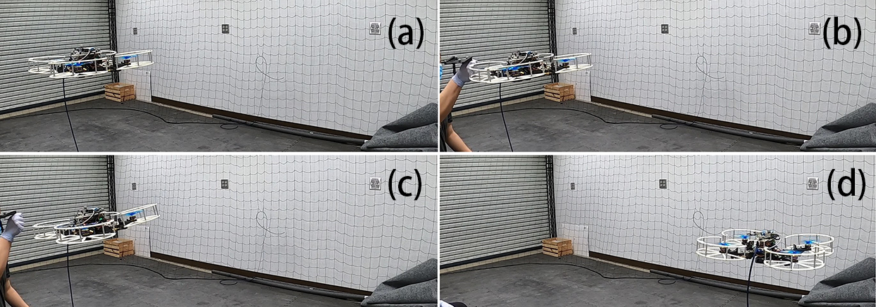
As UAVs are tasked to explore more dynamic environments, the robot can be hit by an obstacle while hovering. We call this type of collision as a passive collision. ARQ can handle passive collisions thanks to its equipped Hall sensors that allow for rapid collision detection while hovering. In our tests, the ARQ is being hit along the direction of an arm when it is hovering. We track actual and desired states during the passive collision recovery in Fig. 6. Desired values are plotted in black dashed curves. A vertical dotted line represents the time when the recovery controller is triggered.

Results demonstrate that ARQ can sustain flight after being passively hit at a collision speed of 1.3 m/s (i.e. the norm of the vehicle’s linear velocity after the collision). After the collision is detected and characterized, ARQ computes a smooth stabilizing trajectory, the initial velocities of which match the ones when recovery control begins. The geometric controller commands ARQ to track the desired trajectory. However, irregular changes in velocities are observed due to the body morphing (Fig. 7.c). Body morphing delays trajectory tracking in the direction; however, ARQ can still converge to desired states quickly and sustain stable flight. Low tracking errors in Fig. 6 support the claim that ARQ’s arms remain rigid to the extent possible during free flight.
VI-B Wall Collision
In the wall collision test, we command ARQ to follow a trajectory that intersects with the wall. The position of the wall is entirely unknown to the robot before the collision. We consider single-arm and two-arm collision types, and repeat multiple trials to evaluate consistency of collision recovery.
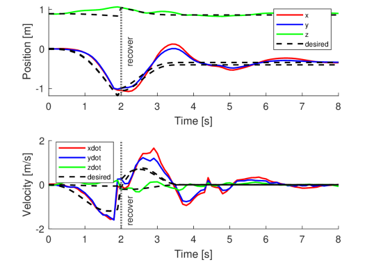


Figure 8 shows sample trajectories of single- and two-arm wall collision. Figure 9 highlights snapshots of a sample single-arm wall collision trial. Testing reveals that ARQ can detect the wall accurately and quickly, then recover from collision and sustain flight afterwards with a speed of up to 2.58 m/s, which is greater than previously-reported maximum feasible velocities of 1.0 m/s in [19] and 2.0 m/s in [29]. Results validate that ARQ can also estimate the intensity and orientation of two-arm collision accurately, to sustain stable flight with a collision speed of 1.92 m/s.
We evaluate consistency of collision recovery by executing 20 consecutive wall collision tests in both single-arm and two-arm types (10 in each case; see supplementary video). ARQ had 9/10 successful recoveries (survive collisions and sustain flight) for the two-arm type and 8/10 successful recoveries for the single-arm type at the highest collision speeds, respectively. The robot failed to detect the collision for the only failure in two-arm collision tests, while the ARQ did detect the collision but was unable to stabilize itself due to large inclination angles in the unsuccessful single-arm recovery.
To demonstrate the individual contribution of compliance and the recovery control components, two additional wall tests are conducted with a collision speed of 2.3 m/s. In the first test, the arms remain compliant but the recovery controller is disabled. In the second test, we fix the arms in place using custom jigs (these add 25 g of weight to the robot) while the recovery controller is disabled. Experimental trials (see supplementary video) show that compliance alone can reduce collision impact (as expected), but cannot help sustain fight; the robot falls to the ground after getting stuck to the wall for several seconds because of lack of recovery control. In the second test, we observe a worse impact which makes the robot fall to the ground immediately. The two tests support our hypothesis that compliance can reduce detrimental impacts from collisions while recovery control is essential to sustain fight afterwards.
VI-C Pole Collision
The robot can also recover from collisions with cylindrical/pole-like objects. In our tests, we use a cylinder of 300 mm diameter (Fig. 10.a) and command ARQ to hit the object with a collision speed of 2.04 m/s.
Testing demonstrates that ARQ can accurately detect pole collisions without any additional changes in hardware and software. The recovery process is very similar to the one with vertical walls, except the collision intensity (0.20) is much smaller, due to the shape of the obstacle. However, the recovery controller still manages to stabilize the robot with a hovering position close to the obstacle. The recovery does not have multiple discontinuous phases as in [31], and the robot tracks a smooth trajectory throughout the recovery.

VI-D Unstructured Surface Collision
Unlike IMU-based methods, ARQ does not require prior knowledge of collision models to handle collisions. We design a collision test on an unstructured surface (Fig. 10.b) to demonstrate this property. It is very challenging to derive a contact model for such irregular surfaces, while the collision position is uncertain that makes it even harder to detect the collision based on contact modeling.
We command ARQ to hit the unstructured surface with a collision speed of m/s. Testing demonstrates that ARQ can quickly and accurately detect collisions with unstructured surfaces thanks to the Hall sensors along the arms. Following a smooth desired trajectory after the collision, ARQ can stabilize itself and return to the hovering state. ARQ’s ability to survive a collision with the unstructured surface is key for UAVs to be deployed in unknown environments.
VI-E Free Fall
To better demonstrate the benefit of adding compliance, we conduct a free fall test with ARQ (Fig. 11). ARQ is found to survive free falls from 1.8 m high and reaching a maximum velocity of 5.9 m/s without any damage to the robot.222The battery is removed in this test as the physical connection in this first prototype is loose, but future iterations of the robot will resolve this; however, removing the battery does not alter the nature of the free fall test. The robot weighs kg without the battery.

VII Conclusions
Contributions and Key Findings
The paper introduces a novel actively resilient quadrotor (ARQ) that can detect collisions quickly and accurately while staying compliant to mitigate damaging collision impacts. The arm is shown to successfully meet the challenge of retaining rigidity in the absence of collision (i.e. during free flight) while allowing one passive degree of freedom in the direction along the arm. Four Hall sensors with shock absorbers make ARQ able to detect collision without IMU data and prior modeling information for obstacles. With the extra resilience to collisions, we propose a new collision detection and characterization method, followed by a novel recovery control method to generate and track a smooth trajectory for collision recovery.
Experimental results demonstrate that ARQ can detect and recover from several types of collision at high speeds. We further study passive collisions (i.e. the robot being hit by a moving obstacle), which may occur unexpectedly at dynamic environments. In all cases, the robot can recover from collisions and sustain flight afterwards. ARQ had 80% success rate for single-arm wall collisions at a speed of 2.58 m/s and 90% for two-arm wall collisions at 1.92 m/s.
Directions for Future Work
Despite the robot’s collision-resilient performance demonstrated herein across objects that are predominantly encountered in applications [29], the current design is unable to detect and react to perpendicular obstacles (e.g., collisions from the top or the bottom) or purely rotational impacts. Future directions of research include 1) improved design of the protective cage to handle perpendicular to the frame and purely rotational collisions and to adapt to collisions with large inclination angles, 2) a comprehensive study to identify feasible maximum velocities for collision with a larger set of obstacles, and 3) deployment and testing in outdoor natural environments.
References
- [1] S. Gupte, P. I. T. Mohandas, and J. M. Conrad, “A survey of quadrotor unmanned aerial vehicles,” in Proceedings of IEEE Southeastcon, 2012, pp. 1–6.
- [2] K. Karydis and V. Kumar, “Energetics in robotic flight at small scales,” Interface Focus, vol. 7, 2017.
- [3] T. Lee, M. Leok, and N. H. McClamroch, “Geometric tracking control of a quadrotor uav on se (3),” in IEEE Conference on Decision and Control (CDC), 2010, pp. 5420–5425.
- [4] D. Mellinger, N. Michael, and V. Kumar, “Trajectory generation and control for precise aggressive maneuvers with quadrotors,” The International Journal of Robotics Research, vol. 31, no. 5, pp. 664–674, 2012.
- [5] D. Brescianini, M. Hehn, and R. D’Andrea, “Quadrocopter pole acrobatics,” in IEEE/RSJ International Conference on Intelligent Robots and Systems (IROS), 2013, pp. 3472–3479.
- [6] J. Thomas, G. Loianno, J. Polin, K. Sreenath, and V. Kumar, “Toward autonomous avian-inspired grasping for micro aerial vehicles,” IOP Bioinspiration & Biomimetics, vol. 9, no. 2, p. 025010, 2014.
- [7] J. Thomas, G. Loianno, M. Pope, E. W. Hawkes, M. A. Estrada, H. Jiang, M. R. Cutkosky, and V. Kumar, “Planning and control of aggressive maneuvers for perching on inclined and vertical surfaces,” in ASME International Design Engineering Technical Conferences and Computers and Information in Engineering Conference, 2015.
- [8] S. Tang, V. Wüest, and V. Kumar, “Aggressive flight with suspended payloads using vision-based control,” IEEE Robotics and Automation Letters, vol. 3, no. 2, pp. 1152–1159, 2018.
- [9] D. Falanga, K. Kleber, S. Mintchev, D. Floreano, and D. Scaramuzza, “The foldable drone: A morphing quadrotor that can squeeze and fly,” IEEE Robotics and Automation Letters, vol. 4, no. 2, pp. 209–216, 2018.
- [10] N. Bucki and M. W. Mueller, “Design and control of a passively morphing quadcopter,” in IEEE International Conference on Robotics and Automation (ICRA), 2019, pp. 9116–9122.
- [11] K. Mohta, M. Watterson, Y. Mulgaonkar, S. Liu, C. Qu, A. Makineni, K. Saulnier, K. Sun, A. Zhu, J. Delmerico, et al., “Fast, autonomous flight in gps-denied and cluttered environments,” Journal of Field Robotics, vol. 35, no. 1, pp. 101–120, 2018.
- [12] G. Aoude, B. Luders, J. Joseph, N. Roy, and J. P. How, “Probabilistically safe motion planning to avoid dynamic obstacles with uncertain motion patterns,” Auton. Robots, vol. 35, no. 1, pp. 51–76, 2013.
- [13] D. Falanga, K. Kleber, and D. Scaramuzza, “Dynamic obstacle avoidance for quadrotors with event cameras,” Science Robotics, vol. 5, no. 40, 2020.
- [14] N. Bucki and M. W. Mueller, “Improved quadcopter disturbance rejection using added angular momentum,” in IEEE/RSJ International Conference on Intelligent Robots and Systems (IROS), Oct 2018, pp. 4164–4170.
- [15] A. De Luca and R. Mattone, “Sensorless robot collision detection and hybrid force/motion control,” in IEEE international conference on robotics and automation (ICRA), 2005, pp. 999–1004.
- [16] K. Karydis, D. Zarrouk, I. Poulakakis, R. S. Fearing, and H. G. Tanner, “Planning with the star (s),” in IEEE/RSJ International Conference on Intelligent Robots and Systems (IROS), 2014, pp. 3033–3038.
- [17] T. Erez and E. Todorov, “Trajectory optimization for domains with contacts using inverse dynamics,” in IEEE/RSJ International Conference on Intelligent Robots and Systems (IROS), 2012, pp. 4914–4919.
- [18] M. Posa, C. Cantu, and R. Tedrake, “A direct method for trajectory optimization of rigid bodies through contact,” The International Journal of Robotics Research, vol. 33, no. 1, pp. 69–81, 2014.
- [19] T. Tomić, C. Ott, and S. Haddadin, “External wrench estimation, collision detection, and reflex reaction for flying robots,” IEEE Transactions on Robotics, vol. 33, no. 6, pp. 1467–1482, 2017.
- [20] Y. Mulgaonkar, A. Makineni, L. Guerrero-Bonilla, and V. Kumar, “Robust aerial robot swarms without collision avoidance,” IEEE Robotics and Automation Letters, vol. 3, no. 1, pp. 596–603, 2017.
- [21] Y. Mulgaonkar, W. Liu, D. Thakur, K. Daniilidis, C. J. Taylor, and V. Kumar, “The tiercel: A novel autonomous micro aerial vehicle that can map the environment by flying into obstacles,” in IEEE International Conference on Robotics and Automation (ICRA), 2020, pp. 7448–7454.
- [22] S. Mintchev, S. de Rivaz, and D. Floreano, “Insect-inspired mechanical resilience for multicopters,” IEEE Robotics and Automation Letters, vol. 2, no. 3, pp. 1248–1255, 2017.
- [23] A. Klaptocz, A. Briod, L. Daler, J.-C. Zufferey, and D. Floreano, “Euler spring collision protection for flying robots,” in IEEE/RSJ International Conference on Intelligent Robots and Systems (IROS), 2013, pp. 1886–1892.
- [24] R. Naldi, A. Torre, and L. Marconi, “Robust control of a miniature ducted-fan aerial robot for blind navigation in unknown populated environments,” IEEE Transactions on Control Systems Technology, vol. 23, no. 1, pp. 64–79, 2014.
- [25] A. Briod, P. Kornatowski, J.-C. Zufferey, and D. Floreano, “A collision-resilient flying robot,” Journal of Field Robotics, vol. 31, no. 4, pp. 496–509, 2014.
- [26] P. Sareh, P. Chermprayong, M. Emmanuelli, H. Nadeem, and M. Kovac, “Rotorigami: A rotary origami protective system for robotic rotorcraft,” Science Robotics, vol. 3, no. 22, p. eaah5228, 2018.
- [27] J. Shu and P. Chirarattananon, “A quadrotor with an origami-inspired protective mechanism,” IEEE Robotics and Automation Letters, vol. 4, no. 4, pp. 3820–3827, 2019.
- [28] A. Battiston, I. Sharf, and M. Nahon, “Attitude estimation for collision recovery of a quadcopter unmanned aerial vehicle,” The International Journal of Robotics Research, vol. 38, no. 10-11, pp. 1286–1306, 2019.
- [29] G. Dicker, F. Chui, and I. Sharf, “Quadrotor collision characterization and recovery control,” in IEEE International Conference on Robotics and Automation (ICRA), 2017, pp. 5830–5836.
- [30] A. Briod, P. Kornatowski, A. Klaptocz, A. Garnier, M. Pagnamenta, J.-C. Zufferey, and D. Floreano, “Contact-based navigation for an autonomous flying robot,” in IEEE/RSJ International Conference on Intelligent Robots and Systems (IROS), 2013, pp. 3987–3992.
- [31] G. Dicker, I. Sharf, and P. Rustagi, “Recovery control for quadrotor uav colliding with a pole,” in IEEE/RSJ International Conference on Intelligent Robots and Systems (IROS), 2018, pp. 6247–6254.
- [32] D. Mellinger and V. Kumar, “Minimum snap trajectory generation and control for quadrotors,” in IEEE International Conference on Robotics and Automation (ICRA), 2011, pp. 2520–2525.
- [33] C. Richter, A. Bry, and N. Roy, “Polynomial trajectory planning for aggressive quadrotor flight in dense indoor environments,” in Robotics Research, 2016, pp. 649–666.