Intensity equations for birefringent spin lasers
Abstract
Semiconductor spin lasers are distinguished from their conventional counterparts by the presence of spin-polarized carriers. The transfer of angular momentum of the spin-polarized carriers to photons provides important opportunities for the operation of lasers. With the injection of spin-polarized carriers, which lead to the circularly polarized light, the polarization of the emitted light can be changed an order of magnitude faster than its intensity. This ultrafast operation of spin lasers relies on a large birefringence, usually viewed as detrimental in spin and conventional lasers. We introduce a transparent description of spin lasers using intensity equations, which elucidate the influence of birefringence on the intensity and polarization modulation of lasers. While intensity modulation is independent of birefringence, for polarization modulation an increase in birefringence directly increases the resonant frequency. Our results for dynamical operation of lasers provide a guide for their spin-dependent response and spintronic applications beyond magnetoresistance.
.1 I. Introduction
Introducing spin-polarized carriers in semiconductors provides both an opportunity to exceed the performance of best conventional lasers and realize room-temperature spintronic applications, beyond the usual magnetoresistive effects. While typical spintronic devices rely on unipolar transport: only one type of carriers (electrons) plays an active role, laser are bipolar devices, a simultaneous description of electrons and holes is crucial Chuang:2009 ; Coldren:2012 ; Michalzik:2013 .
Spin lasers Hallstein1997:PRB ; Ando1998:APL ; Rudolph2005:APL ; Gerhardt2006:EL ; Holub2007:PRL ; Holub2007:PRL ; Hovel2008:APL ; Basu2009:PRL ; Saha2010:PRB ; Iba2011:APL ; Frougier2013:APL ; Cheng2014:NN embody common elements for spintronic devices: spin injection, relaxation, transport, and detection DasSarma2001:SSC ; Maekawa:2002 ; Zutic2004:RMP ; Tsymbal:2019 ; Hirohata2020:JMMM . This is depicted in Fig. 1(a) for vertical cavity surface emitting lasers (VCSELs) where spin-polarized carriers are injected from magnetic contacts or, alternatively, by using circularly polarized light Zutic2020:SSC . The spin transport is dominated by electrons (bright colors) since the spin imbalance of holes (pale colors) is quickly lost, as they experience stronger spin-orbit coupling and have a much shorter spin relaxation time, Zutic2004:RMP ; Fabian2007:APS ; Hilton2002:PRL . Through the transfer of angular momentum, the spin injection is detected as a circularly polarized light, the photon densities of positive and negative helicity, and , are inequivalent.
Even though the individual elements of spin laser have been extensively studied Zutic2020:SSC , the interplay between different timescales for carrier, spin, and photon dynamics, is far from understood. For example, unlike in common spintronic devices, where to preserve spin information a long spin relaxation time of electrons is desirable Tsymbal:2019 , for optimal dynamical operation instead a very short electron spin relaxation time is sought Lindemann2019:N .
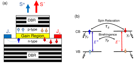
While many trends in spin lasers can be understood by simply introducing spin-resolved quantities in simple rate equations for conventional lasers Chuang:2009 ; Coldren:2012 ; Michalzik:2013 , this approach leaves large uncertainties for the dynamical operation of lasers which can be dominated by optical anisotropies, such as the anisotropy of refractive index–birefringence. To address this situation, and motivated by the recent experimental advances showing that a large birefringence with spin injection in III-V quantum well-based lasers supports a much faster room-temperature operation than in the best conventional lasers Lindemann2019:N , we introduce here transparent intensity equations to elucidate dynamical operation of spin lasers relying on the optical transitions between conduction band (CB) and the heavy hole states in the valence band (VB), illustrated in Fig. 1(b).
An advantage of the intensity equations is their simplicity, instead of the helicity-resolved electric fields with complex amplitudes, , for the considered optical transitions in Fig. 1(b), it is sufficient to use real-valued photon densities, . Our approach offers analytical solutions for several situations and provides a direct link to the extensively studied rate equations for both conventional and spin lasers Chuang:2009 ; Coldren:2012 ; Michalzik:2013 ; Rudolph2005:APL ; Holub2007:PRL ; Gothgen2008:APL ; Saha2010:PRB ; Lee2010:APL ; Lee2012:PRB ; Lee2014:APL
These intensity equations are closely related to the spin-flip model SanMiguel1995:PRA , introduced to explain the polarization dynamics in conventional VCSELs and later used for describing spin lasers SanMiguel1997:IEEE ; vanExter1998:PRA ; Mulet2002:IEEEJQE ; Sande2003:PRA ; Li2010:APL ; Gerhardt2011:APL ; Al-Seyab2011:IEEEPJ ; Gerhardt2012:AOT ; Alharthi2015:APL ; Lindemann2016:APL ; Yokota2018:APL ; Adams2018:SST . We show how to correct some of the assumptions in that model, which are particularly important for spin lasers and their potential to be used for ultrafast operation as a building block of high-performance optical interconnects FariaJunior2015:PRB ; Lindemann2019:N ; Yokota2018:APL , importing to for a growing need of transferring information Hecht2016:N ; Miller2017:JLT ; Jones2018:N . Following this introduction, in Sec. II we describe our intensity equations. In Sec. III we introduce dynamic operation of lasers and how it is experimentally realized in highly-birefringent spin lasers. In Sec. IV our results for intensity and polarization modulation are given, and in Sec. V we provide conclusions and note some open questions for future work.
I II. Intensity Equations
The polarization dynamics of VCSELs has been successfully described by the influential spin-flip model (SFM) SanMiguel1995:PRA and widely applied to conventional lasers, having no external source of spin-polarized carriers SanMiguel1997:IEEE ; vanExter1998:PRA ; Mulet2002:IEEEJQE ; Sande2003:PRA . For a spin laser the corresponding equations can be generalized by including injection of spin-polarized carriers as shown in Fig. 1(a). Since the hole spin relaxation is typically much faster than for electrons, there is no depicted spin imbalance in the -region Zutic2004:RMP .
Following the conservation of angular momentum and the optical selection rules Zutic2004:RMP , Fig. 1(b) illustrates the SFM which focuses on the gain region based on a quantum well (QW) where its confinement splits the heavy and light hole degeneracy. In the resulting equation it is then sufficient to consider optical transition between the CB, with the projection of the total angular momentum and the VB with for heavy holes,
| (1) | |||||
| (2) | |||||
| (3) | |||||
where the normalized (see Appendix) circularly polarized components of slowly varying amplitudes of the electric field are related to linear modes by . Corresponding photon densities are , with a photon lifetime . is the total number of carriers with a recombination rate , is the population difference between spin-down and spin-up electrons with a spin relaxation lifetime , and is the linewidth enhancement factor. and are the dichrosism and linear birefringence, the amplitude and phase anisotropies of the cavity. is the time-dependent injection rate of spin-up () and spin-down () carriers.
The SFM equations contain complex amplitudes of the electric field, which can be expressed in terms of real quantities as . Therefore, the equations can be rewritten in terms of the dimensionless real quantities, such that all the frequencies are scaled to and differentiation expressed with respect to dimensionless time, , as
| (4) | |||
| (5) | |||
| (6) | |||
| (7) | |||
| (8) |
where is the phase difference between the two linear modes and is the total injection.
I.1 A. Intensity equations without spin injection
In the absence of spin injection, , the spin polarization of carriers is very small, i.e., is negligible. Therefore, the time evolution of the phase can be approximated, using dimensionless time , by
| (9) |
Considering typically small spin relaxation times in semiconductors used in gain region of a laser Lindemann2016:APL ; Lindemann2019:N , , we can adiabatically eliminate () to obtain
| (10) |
With the approximations in Eqs. (9) and (10), the SFM from Eqs. (1)-(3) is reduced to dynamic equations for the light intensities and total carrier number
| (11) | |||||
| (12) | |||||
| (13) |
where the cross-saturation coefficients are which suppress the intensity of the emitted light as the carrier injection is increased. However, the above equations arising from the SFM, lack the well-known self-saturation effects in conventional lasers known to be crucial in limiting the intensity of the emitted light at large injection levels Chuang:2009 ; Coldren:2012 ; Lee1993:OQE and also studied in the rate-equation description of spin lasers Holub2007:PRL ; Gothgen2008:APL .
For a more complete description of the gain saturation (also referred to as the gain compression), we phenomenologically introduce self-saturation terms with coefficients and for the and modes
| (14) | |||||
| (15) | |||||
| (16) |
where we note that in describing conventional lasers the gain saturation coefficients are often simply given by and Chuang:2009 ; Coldren:2012 ; Lee1993:OQE .
I.2 B. Intensity equations with spin injection
The immediate effect of a spin injection, , is a significant spin polarization of carriers, such that
| (17) |
which in turn leads to additional terms in the equations for intensities and phase
| (20) |
| (21) |
The above Eqs. (I.2)-(LABEL:eq:phi_SAT), with real-valued quantities, can be used to study the dynamic operation of spin lasers and provides a good agreement with the common SFM SanMiguel1995:PRA , as shown in Appendix. The transparency of this approach allows analytical solutions of intensity modulation response by a small-signal analysis and offers opportunities to further explore the dynamics of highly-birefringent lasers using linear analysis.
II III. Dynamic Operation
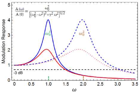
The most attractive properties of conventional lasers usually lie in their dynamical performance, suitable for transferring information and implementing optical interconnects Chuang:2009 ; Coldren:2012 ; Michalzik:2013 . A damped driven harmonic oscillator, , provides a valuable model for the dynamic operation of lasers Lee2012:PRB , where is the angular frequency of the simple harmonic oscillator, is the damping constant, is the amplitude of the driving force and is the mass.
Such a harmonic oscillator shares with lasers its resonant behavior near the angular frequency and a large reduction of the amplitude, , for , as depicted for two resonant frequencies in Fig. 2,
| (22) |
The reduction of by -3 dB, compared to , gives a useful frequency range over which substantial signals can still be transferred, corresponding to the modulation bandwidth of a laser Chuang:2009 ; Lee2012:PRB .
A challenge for spin lasers is to seek improving dynamic operation over their best conventional counterparts. Already the first VCSEL with optical spin injection Hallstein1997:PRB has supported a high-frequency operation. The transfer of a Larmor precession of the electron spin to the spin of photons was shown polarization oscillation of the emitted light up to 44 GHz in a magnetic field of 4 T at 15 K Hallstein1997:PRB . While this approach is limited to cryogenic temperatures and does not allow an arbitrary modulation of the polarization, needed for high-speed information transfer, nor it is clear if the resulting modulation bandwidth (recall Fig. 2) could exceed those from conventional semiconductors, it has stimulated subsequent studies in spin lasers.
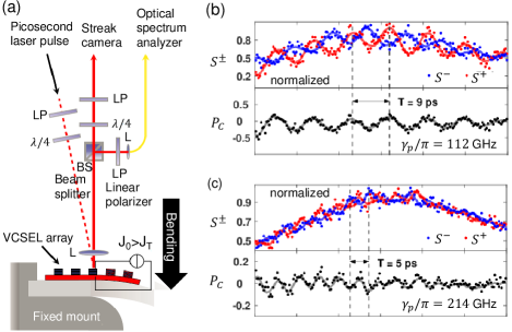
One such realization of spin lasers supporting room-temperature ultrafast operation was demonstrated in highly-birefringent VCSELs Lindemann2019:N , as shown in Fig. 3. The role of birefringence can be understood from Fig. 1(b) and SFM or intensity equations from Sec. II. Since the birefringence is responsible for the beating between the emitted light of different helicities, the changes in the polarization of the emitted light,
| (23) |
can be faster than the changes in the light intensity. While initially these polarization changes were limited to 10 GHz for commercial III-V VCSELs to which spin-polarized carriers were optically injected Gerhardt2011:APL ; Li2010:APL , subsequent theoretical predictions of much higher strain-enhanced birefringence values FariaJunior2015:PRB and their experimental realization Lindemann2016:APL have paved the way for spin lasers that could operate faster than the best conventional counterparts. Specifically, the realization of higher birefringence values, using elasto-optic effect up to GHz Panajotov2000:APL , asymmetric heating up to GHz Pusch2017:APL , integrated surface gratings up to 98 GHz Pusch2019:EL , and mechanical bending reaching 259 GHz Pusch2015:EL , by itself only supports static implications of birefringence due to mode splitting in VCSEL. However, Fig. 3 also reveals that high birefringence is also compatible with ultrafast oscillations in .
To study the dynamic operation of spin lasers, with spin polarization of injected carriers
| (24) |
and conventional lasers as their special limiting case, where , it is convenient that each of the key quantities, (such as, , , and ), is decomposed into a steady-state and a modulated part Lee2012:PRB ,
| (25) |
where we can assume harmonic modulation .
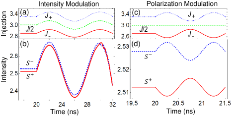
We focus on the intensity and polarization modulation (IM, PM), illustrated in Fig. 4. IM for a steady-state polarization implies (unless ),
| (26) |
where is the angular modulation frequency. Such a modulation can be contrasted with PM which also has , but remains constant const ,
| (27) |
In spin lasers it is also possible to consider other modulation schemes with . For example, a complex modulation Boeris2012:APL can suppress an undesired frequency modulation, or chirp, a direct consequence of IM and the carrier dependence of the refractive index in the gain region. In addition to faster operation, by modulating the polarization of the emitted light rather than its intensity Lindemann2019:N ; Hopfner2014:APL , spin lasers offer a reduced noise and an improved signal transfer Wasner2015:APL .
III IV. Intensity and polarization modulation response
The modulation response in conventional lasers, typically realized using IM, can be simply summarized by relating their resonant (relaxation-oscillation) frequency and the resulting usable frequency range given by the modulation bandwidth Chuang:2009 ; Coldren:2012 (see Fig. 2),
| (28) |
The modulation bandwidth can be estimated by the resonant frequency, , where is the gain constant, is the steady-state photon density, the photon lifetime, used also in the SFM, and is the simplified parameterization of the gain saturation, noted in Sec. IIA. To enhance the bandwidth one can seek to enhance by materials design to enlarge , decrease by reducing the reflectivity of mirrors forming the resonant cavity (recall Fig. 1), or by increasing to attain a larger . While the last approach is the most common, we can see that it comes not only at the cost of the higher-power consumption, but that a finite is responsible for the saturation of as is increased.
However, this common analysis using Eq. (28) excludes the influence of birefringence, which experimentally can exceed GHz Pusch2015:EL , and, even for conventional lasers with , it is unclear what would be its influence on and the corresponding modulation bandwidth. In spin lasers the situation is further complicated as the birefringence can be viewed as undesirable and there efforts in designing lasers to minimize it Hovel2008:APL ; Frougier2015:OE ; Yokota2017:IEEEPTL ; Fordos2017:PRA .
To elucidate the role of birefringence of the modulation response we analyze the dynamic operation of the laser using a perturbative approach to the steady-state response, using a decomposition as in Eq. (25), known also as the small signal analysis (SSA) Chuang:2009 ; Coldren:2012 , limited to a small modulation. This approach is readily generalized for spin lasers Lee2010:APL , with for IM and for PM.
From the intensity equations we can obtain and the (modulation) frequency response functions
| (29) |
For they reduce to, , usually normalized to its value, just as in Eq. (22),
| (30) |
where, and damping rate can be analytically extracted from Eq. (14)-(16). For example, assuming , we can obtain the steady-state value, and , and conclude that the normalized threshold values are
| (31) |
We can then express
| (32) | |||||
| (33) |
while assuming instead , , and would retain the same form, but with .
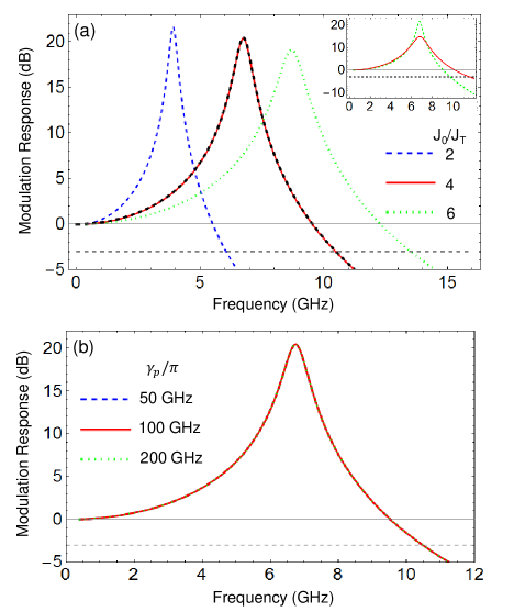
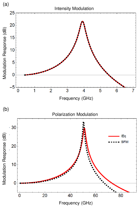
To illustrate the effects of injection and birefringence on IM explicitly, we calculate the modulation response for a series of injection and birefringence. As shown in Fig. 5, the resonant frequency as well as bandwidth increase with larger injection, which is also implied by Eqs. (28) and (32). Note that there is a good agreement between the numerical calculation and analytical expressions in Eqs. (30), (32), (33). Additionally, the IM bandwidth can be enhanced by increasing the polarization of injection , without visibly altering the resonant frequency, as shown in the inset of Fig. 5(a) Using the rate equations (in the absence of birefringence) such as increase in has enhanced both the bandwidth and the resonant frequency Lee2010:APL ; Banerjee2011:JAP . In contrast, from Fig. 5(b), IM response is unaffected by birefringence. This can be understood from the intensity equations [Eqs. (I.2)-(LABEL:eq:phi_SAT)], in which birefringence only changes the phase difference between and modes, rather than the intensities.
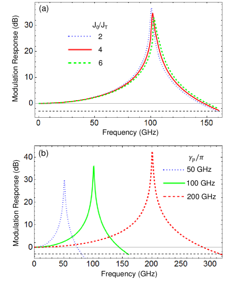
Due to the complexity of the analytical expressions for the PM response, we analyze numerically the effects of injection and birefringence on PM. As shown in Fig. 6(a), the PM resonant frequency and bandwidth increase only slightly (%) with a three times larger injection. In contrast, the increase in birefringence significantly enhances the resonant frequency and bandwidth. Remarkably, the birefringence itself approximately determines the PM resonant frequency, and the striking increase in the resonant frequency seen from Fig. 6(b) is well described by . Since birefringence larger than 200 GHz has been realized experimentally Pusch2015:EL ; Lindemann2019:N , it can be employed to overcome the bandwidth bottleneck Hecht2016:N of conventional IM (35 GHz) Haghighi2018:ISLC . From the results in Fig. 6(b), guided by the room-temperature experiments on the highly-birferingent spin lasers Lindemann2019:N , we can see that the birefringence of 200 GHz corresponds to the bandwidth of 300 GHz, about an order of magnitude larger than in the best conventional lasers Haghighi2018:ISLC , offering a promising approach for high-performance optical interconnect based on spin lasers.
A common strategy to increase the resonant frequency and bandwidth in conventional lasers can be inferred from Eq. (28) suggesting a desirable role of a large-injection regime. However, depending on gain saturation, inevitable in semiconductor lasers Lee1993:OQE , which limits the intensity of emission with increasing injection, there is a detrimental impact on the modulation response and the increased power consumption.
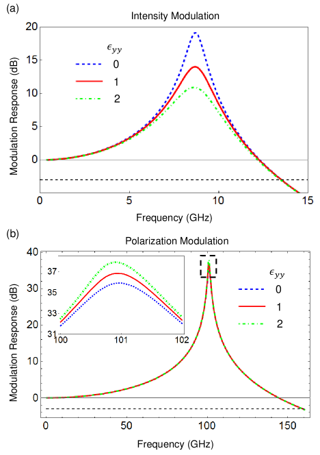
We illustrate in Fig. 7 the effects of self-saturation, absent in SFM, on IM and PM response. For simplicity, we consider a case of -mode lasing, i.e., , which allows a focus on the saturation of the dominant mode, while the effect of -mode saturation can be inferred analogously. For IM, the peak value of response is reduced with larger saturation , while the resonant frequency and bandwidth remain unchanged. The self-saturation effect on PM is much smaller and hardly noticeable, which can only been seen from the inset of Fig. 7(b). We see that the PM response is insensitive both to injection [Fig. 6(a)] and saturation, as it relies on the dynamics of polarization instead of intensity. Such distinct properties further make it a promising candidate for applications in low-energy ultrafast optical communication. Specifically, ultrafast operation in highly-birefringent spin lasers can be realized at low injection intensities, , which has been recently demonstrated with electrically-tunable birefringence, even at elevated temperatures C Lindemann2020:AIPA . This could greatly reduce the power consumption, which is estimated to be an order of magnitude lower than in the state-of-the art conventional lasers Lindemann2019:N ; Moser2012:EL .
IV V. Conclusions and Outlook
The transparency of the developed intensity equations provides an intuitive description of intensity and polarization dynamics for both conventional and spin lasers. This approach, motivated by a popular spin-flip model SanMiguel1995:PRA , offers not only simpler calculations and analytical results, but also a direct connection to widely-used rate equations Chuang:2009 ; Coldren:2012 now including the missing description of optical anisotropies. While compared to the spin-flip model these intensity equations are obtained by eliminating the population difference between the spin-up and spin-down electrons, this approximation is accurately satisfied for spin lasers suitable for ultrafast operation and implementing optical interconnects Lindemann2019:N ; Yokota2018:APL ; Lindemann2020:AIPA .
The introduced intensity equations overcome several limitations of the initial spin-flip model SanMiguel1995:PRA , which neglected gain saturation, particularly important for a large-injection regime, and assumed identical spin relaxation times of holes and electrons, despite characteristic times being typically several orders of magnitude shorter in holes Zutic2004:RMP . Instead, as relevant to most of the fabricated spin lasers, we have considered a vanishing spin relaxation time for holes. As shown within the generalized rate-equation description of spin lasers Lee2014:APL , this assumption can be relaxed to better describe GaN quantum well spin lasers FariaJunior2017:PRB , where both electron and hole spin relaxation times are comparable Brimont2009:JAP , but have not been simultaneously considered in describing experiments Bhattacharya2017:PRL .
Our findings on the modulation response reveal that for the intensity modulation, commonly used in conventional lasers, the corresponding resonant frequency and the bandwidth are independent of the experimentally demonstrated range of a linear birefringence. In contrast, for polarization modulation the resonant frequency, which can also give an estimate for the corresponding maximum bandwidth, grows linearly with the increase in such birefringence, to reach values largely exceeding the resonant frequency in fastest conventional lasers. There is a growing support that such improvements can be realized with different gain regions and cover a wide range of the emitted light, from 850 nm to 1.55 m Lindemann2019:N ; Lindemann2016:APL ; Yokota2018:APL ; Yokota2018:CLEO ; Lindemann2020:AIPA ; Lindemann2020:P .
Presently, it is unclear what are the frequency limitations in the operation of spin lasers, for which both strain-enhanced birefringence and short spin relaxation times could help FariaJunior2017:PRB ; Lindemann2019:N . There are suggestions how the resonant frequency and the bandwidth could be further enhanced by choosing two-dimensional materials for the gain region and perhaps by employing magnetic proximity effects Lindemann2019:N ; Zutic2019:MT . Instead of using pulsed ps optical spin injection (recall the approach from Fig. 3), it would be desirable to seek alternative methods for modulation of the carrier spin polarization and consider phenomena that were previously not studied in the context of spin lasers. For example, using ultrafast demagnetization Battiato2010:PRL ; Kampfrath2013:NN , ultrasfast magnetization reversal Garzon2008:PRB ; Kirilyuk:2019 , or ultrafast modulation of spin and optical polarization using bound states in quantum wells Rozhansky2020:PRB ; Mantsevich2019:PRB . Gate-controlled reversal of helicity was predicted in two-dimensional topological materials Xu2020:PRL , while electrical injection from iron GaAs-based light-emitting diode was demonstrated to support helicity switching at room temperature Nishizawa2017:PNAS ; Nishizawa2018:APE ; Munekata2020:SPIE .
While our focus was on vertical cavity surface emitting lasers (VCSELs) Michalzik:2013 , typically used to implement spin laser, it would be interesting to consider if these intensity equations can also complement the studies of vertical external cavity surface emitting lasers (VECSELs) Frougier2013:APL ; Frougier2015:OE . They have complementary advantages to VCSELs and having an external cavity may offer an additional control optical anisotropy, including birefringence, as well as incorporate magnetic elements close to the gain region for efficient electrical spin injection Frougier2015:OE ; Alouini2018:OE . Efforts to obtain an efficient room-temperature electrical injection in semiconductors with perpendicular magnetic anisotropy of the spin injector Sinsarp2007:JJAP ; Hovel2008:APLa ; Zarpellon2012:PRB could be extended in spin lasers to remove the need to use an external magnetic field to align the magnetization out-of-plane, consistent with the usual optical selection rules Zutic2004:RMP .
In addition to the relevance of spin lasers as emerging room-temperature spintronic devices with operation principles not limited by magnetoresistive effects Zutic2004:RMP ; Tsymbal:2019 ; Zutic2020:SSC ; Hirohata2020:JMMM ; Lin2019:NE , the studied intensity equations could also be helpful in exploring other device concepts. For example, an earlier work on rate equations Lee2010:APL ; Lee2012:PRB was helpful to motivate electrical spin interconnects Dery2011:APL ; Zutic2011:NM ; Zutic2019:MT and phonon lasers Khaetskii2013:PRL , an acoustic analog of lasers which also shares properties with spin-controlled nanomechanical resonators Stadler2014:PRL ; Mantovani2019:PRB .
Acknowledgments
This work has been supported by the NSF ECCS-1810266. We thank N. C. Gerhardt, M. Lindemann, M. R. Hofmann, R. Michalzik, and T. Pusch for valuable discussions.
Appendix A APPENDIX
The quantities in the spin-flip model (SFM) equations SanMiguel1995:PRA are usually studied in the dimensionless form making it important to describe how they are normalized and simplify their relation to other rate-equation description of lasers. Specifically, the quantities in SFM have been normalized as
| (A1) | |||||
| (A2) | |||||
| (A3) |
where are the slowly varying amplitudes of the helicity-resolved components of the electric field, is the steady-state light intensity at twice the threshold injection , are the numbers of spin-up and spin-down electrons, and are the numbers of electrons at the threshold and transparency, respectively. The injection has been normalized with respect to threshold injection . We have assumed in the above normalizations.
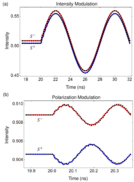
To verify the validity of intensity equations, we compare the numerical results from the intensity equations and SFM. In Fig. 8, we show a comparison of the time evolution of helicity-resolved intensities between intensity equations and SFM under IM and PM, respectively. We see that the agreement in the time evolution is excellent, with only a minor deviation for PM. The comparison of modulation response is illustrated in Fig. 9, which shows a good overall agreement, with only a small discrepancy in the PM response.
References
- (1) S. L. Chuang, Physics of Optoelectronic Devices, 2nd ed. (Wiley, New York, 2009).
- (2) L. A. Coldren, S. W. Corzine, and M. L. Mašović, Diode Lasers and Photonic Integrated Circuits, 2 Edition (Wiley, Hoboken, 2012).
- (3) VCSELs Fundamentals, Technology and Applications of Vertical-Cavity Surface-Emitting Lasers, edited by R. Michalzik (Springer, Berlin, 2013).
- (4) S. Hallstein, J. D. Berger, M. Hilpert, H. C. Schneider, W. W. Rühle, F. Jahnke, S. W. Koch, H. M. Gibbs, G. Khitrova, M. Oestreich, Manifestation of coherent spin precession in stimulated semiconductor emission dynamics, Phys. Rev. B 56, R7076 (1997).
- (5) H. Ando, T. Sogawa, and H. Gotoh, Photon-spin controlled lasing oscillations in surface-emitting lasers, Appl. Phys. Lett. 73, 566 (1998).
- (6) J. Rudolph, S. Döhrmann, D. Hägele, M. Oestreich, and W. Stolz, Room-temperature threshold reduction in vertical-cavity surface-emitting lasers by injection of spin-polarized carriers, Appl. Phys. Lett. 87, 241117 (2005).
- (7) N. C. Gerhardt, S. Hövel, M. R. Hofmann, J. Yang, D. Reuter, A. Wieck, Enhancement of spin information with vertical cavity surface emitting lasers, Electron. Lett. 42, 88 (2006).
- (8) M. Holub, J. Shin, and P. Bhattacharya, Electrical spin injection and threshold reduction in a semiconductor laser, Phys. Rev. Lett. 98, 146603 (2007).
- (9) S. Hövel, A. Bischoff, N. C. Gerhardt, M. R. Hofmann, T. Ackemann, A. Kroner, and R. Michalzik, Optical spin manipulation of electrically pumped vertical-cavity surface-emitting lasers, Appl. Phys. Lett. 92, 041118 (2008).
- (10) D. Basu, D. Saha and P. Bhattacharya, Optical polarization modulation and gain anisotropy in an electrically injected spin laser, Phys. Rev. Lett. 102, 093904 (2009).
- (11) D. Saha, D. Basu, and P. Bhattacharya, High-frequency dynamics of spin-polarized carriers and photons in a laser, Phys. Rev. B 82, 205309 (2010).
- (12) S. Iba, S. Koh, K. Ikeda, and H. Kawaguchi, Room temperature circularly polarized lasing in an optically spin injected vertical-cavity surface-emitting laser with (110) GaAs quantum wells, Appl. Phys. Lett. 98, 081113 (2011).
- (13) J. Frougier, G. Baili, M. Alouini, I. Sagnes, H. Jaffrès, A. Garnache, C. Deranlot, D. Dolfi, and J.-M. George, Control of light polarization using optically spin-injected vertical external cavity surface emitting lasers Appl. Phys. Lett. 103, 252402 (2013).
- (14) J.-Y. Cheng, T.-M. Wond, C.-W. Chang, C.-Y. Dong, and Y.-F Chen, Self-polarized spin-nanolasers, Nat. Nanotechnol. 9, 845 (2014).
- (15) S. Das Sarma, J. Fabian, X. D. Hu, and I. Žutić, Spin electronics and spin computation, Solid State Commun. 119, 207 (2001).
- (16) S. Maekawa, and T. Shinjo, eds., Spin Dependent Transport in Magnetic Nanostructures (Taylor & Francis, New York, 2002).
- (17) I. Žutić, J. Fabian and S. Das Sarma, Spintronics: Fundamantals and applications, Rev. Mod. Phys. 76, 323 (2004).
- (18) Spintronics Handbook Spin Transport and Magnetism, edited by E. Y. Tsymbal and I. Žutić 2nd Edition, (Taylor & Francis/CRC Press, Boca Raton, FL 2019).
- (19) A. Hirohata, K.Yamada, Y.Nakatani, I.-L. Prejbeanu, B. Diény, P. Pirro, and B. Hillebrands, Review on spintronics: Principles and device applications, J. Magn. Magn. Mater. 509, 166711 (2020).
- (20) I. Žutić, G. Xu, M. Lindemann, P. E. Faria Junior, J. Lee, V. Labinac, K. Stojšić, G. M. Sipahi, M. R. Hofmann, and Nils C. Gerhardt, Spin-lasers: spintronics beyond magnetoresistance, Solid State Commun. 316-317, 113949 (2020).
- (21) J. Fabian, A. Mathos-Abiague, C. Ertler, P. Stano, and I. Žutić, Semiconductor spintronics, Acta Phys. Slov. 57, 565 (2007).
- (22) D. J. Hilton and C. L. Tang, Optical orientation and femtosecond relaxation of spin-polarized holes in GaAs, Phys. Rev. Lett. 89, 146601 (2002).
- (23) M. Lindemann, G. Xu, T. Pusch, R. Michalzik, M. R. Hofmann, I. Žutić, and N. C. Gerhardt, Ultrafast spin-Lasers, Nature 568, 212 (2019).
- (24) C. Gøthgen, R. Oszwałdowski, A. Petrou, and I. Žutić, Analytical model of spin-polarized semiconductor lasers, Appl. Phys. Lett. 93, 042513 (2008).
- (25) J. Lee, W. Falls, R. Oszwałdowski, and I. Žutić, Spin modulation in lasers, Appl. Phys. Lett. 97, 041116 (2010).
- (26) J. Lee, R. Oszwaldowski, C. Gothgen, and I. Žutić, Mapping between quantum dot and quantum well lasers: From conventional to spin lasers, Phys. Rev. B 85, 045314 (2012).
- (27) J. Lee, S. Bearden, E. Wasner, and I. Žutić, Spin-lasers: From threshold reduction to large-signal analysis, Appl. Phys. Lett. 105, 042411 (2014).
- (28) M. San Miguel, Q. Feng, and J. V. Moloney, Light-polarization dynamics in surface-emitting semiconductor lasers, Phys. Rev. A 52, 1728 (1995).
- (29) J. Martin-Regalado, F. Prati, M. San Miguel, and N.B. Abraham, Polarization Properties of Vertical-Cavity Surface-Emitting Lasers, IEEE J. Quantum Electron. 33, 765 (1997).
- (30) M. P. van Exter, R. F. M. Hendriks and J. P. Woerdman, Physical insight into the polarization dynamics of semiconductor vertical-cavity lasers, Phys. Rev. A 57, 2080 (1998).
- (31) J. Mulet and S. Balle, Spatio-temporal modeling of the optical properties of VCSELs in the presence of polarization effects, IEEE J. Quantum Electron. 38, 291 (2002).
- (32) G. Van der Sande, J. Danckaert, I. Veretennicoff, T. Erneux, Rate equations for vertical-cavity surface-emitting lasers, Phys. Rev. A 67, 013809 (2003).
- (33) M. Y. Li, H. Jähme, H. Soldat, N. C. Gerhardt, M. R. Hofmann, and T. Ackemann, A. Kroner, and R. Michalzik, Birefringence controlled room-temperature picosecond spin dynamics close to the threshold of vertical-cavity surface-emitting laser devices, Appl. Phys. Lett. 97, 191114 (2010).
- (34) N. C. Gerhardt, M. Y. Li, H. Jähme, H. Höpfner, T. Ackemann, and M. R. Hofmann, Ultrafast spin-induced polarization oscillations with tunable lifetime in vertical-cavity surface-emitting lasers, Appl. Phys. Lett. 99, 151107 (2011).
- (35) R. Al-Seyab, D. Alexandropoulos, I. D. Henning, and M. J. Adams, Instabilities in spin-polarized vertical-cavity surface-emitting lasers, IEEE Photon. J. 3, 799 (2011).
- (36) N. C. Gerhardt and M. R. Hofmann, Spin-controlled vertical-cavity surface-emitting lasers, Adv. Opt. Techn. 2012, 268949 (2012).
- (37) S. S. Alharthi, A. Hurtado, V.-M. Korpijarvi, M. Guina, I. D. Henning, and M. J. Adams, Circular polarization switching and bistability in an optically injected 1300 nm spin-vertical cavity surface emitting laser, Appl. Phys. Lett. 106, 021117 (2015).
- (38) M. Lindemann, T. Pusch, R. Michalzik, N. C Gerhardt, and M. R. Hofmann, Frequency tuning of polarization oscillations: Toward high-speed spin-lasers, Appl. Phys. Lett. 108, 042404 (2016).
- (39) N. Yokota, and K. Nisaka, H.Yasaka, and K. Ikeda, Spin polarization modulation for high-speed vertical-cavity surface-emitting lasers, Appl. Phys. Lett. 113, 171102 (2018).
- (40) M. Adams, N. Li, B. Cemlyn, H. Susanto, and I. Henning, Algebraic expressions for the polarisation response of spin-VCSELs, Semicond. Sci. Technol. 33, 064002 (2018).
- (41) P. E. Faria Junior, G. Xu, J. Lee, N. C. Gerhardt, G. M. Sipahi, and I. Žutić, Towards high-frequency operation of spin-lasers, Phys. Rev. B 92, 075311 (2015).
- (42) J. Hecht, The bandwidth bottleneck, Nature 536, 139 (2016).
- (43) D. A. B. Miller, Attojoule Optoelectronics for Low-Energy Information Processing and Communications - a Tutorial Review, J. Lightwave Tech. 3, 346 (2017).
- (44) N. Jones, The information factories, Nature 561, 163 (2018).
- (45) H.-H. Lee and W. Casperson, Gain and saturation in semiconductor lasers, Opt. and Quant. Electron. 25, 369 (1993).
- (46) K. Panajotov, B. Nagler, G. Verschaffelt, A. Georgievski, H. Thienpont, J. Danckaert, and I. Veretennicoff, Impact of in-plane anisotropic strain on the polarization behavior of vertical-cavity surface-emitting lasers, Appl. Phys. Lett. 77, 1590 (2000).
- (47) T. Pusch, E. La Tona, M. Lindemann, N. C. Gerhardt, M. R. Hofmann, and R. Michalzik, Monolithic vertical-cavity surface-emitting laser with thermally tunable birefringence, Appl. Phys. Lett. 110, 151106 (2017).
- (48) T. Pusch, P. Debernardi, M. Lindemann, F. Erb, N. C. Gerhardt, M. R. Hofmann and R. Michalzik, Vertical-cavity surface-emitting laser with integrated surface grating for high birefringence splitting Electron. Lett. 55, 1055 (2019).
- (49) T. Pusch, M. Lindemann, N. C. Gerhardt, M. R. Hofmann, and R. Michalzik, Vertical-cavity surface-emitting lasers with birefringence above 250 GHz, Electron. Lett. 51, 1600 (2015).
- (50) This is not essential but simplifies our analytical results.
- (51) G. Boeris, J. Lee, K. Vyborny, and I. Žutić, Tailoring chirp in spin-lasers, Appl. Phys. Lett. 100, 121111 (2012).
- (52) H. Höpfner, M. Lindemann, N. C. Gerhardt, and M. R. Hofmann, Controlled switching of ultrafast circular polarization oscillations in spin-polarized vertical-cavity surface-emitting lasers, Appl. Phys. Lett. 104, 022409 (2014).
- (53) E. Wasner, S. Bearden, J. Lee, and I. Žutić, Digital operation and eye diagrams in spin-lasers, Appl. Phys. Lett. 107, 082406 (2015).
- (54) J. Frougier, G. Baili, I. Sagnes, D. Dolfi, J.-M. George, and M. Alouini, Accurate measurement of the residual birefringence in VECSEL: Towards understanding of the polarization behavior under spin-polarized pumping, Opt. Expr. 23, 9573 (2015).
- (55) N. Yokota, R. Takeuchi, H. Yasaka, and K. Ikeda, Lasing polarization characteristics in 1.55-m spin-injected VCSELs, IEEE Photon. Tech. Lett. 29, 711 (2017).
- (56) T. Fordos, H. Jaffres, K. Postava, M. S. Seghilani, A. Garnache, J. Pistora, and H. J. Drouhin, Eigenmodes of spin vertical-cavity surface-emitting lasers with local linear birefringence and gain dichroism, Phys. Rev. A 96, 043828 (2017).
- (57) D. Banerjee, R. Adari, M. Murthy, P. Suggisetti, S. Ganguly, and D. Saha, Modulation bandwidth of a spin laser, J. Appl. Phys. 109, 07C317 (2011).
- (58) N. Haghighi, G. Larisch, R. Rosales, M. Zorn, and J. A. Lott, 35 GHz bandwidth with directly current modulated 980 nm oxide aperture single cavity VCSELs, 2018 IEEE Int. Semiconductor Laser Conf. (ISLC) https://doi.org/10.1109/ ISLC.2018.8516258 (2018).
- (59) M. Lindemann, N. Jung, P. Stadler, T. Pusch, R. Michalzik, M. R. Hofmann, and N. C. Gerhardt, Bias current and temperature dependence of polarization dynamics in spin-lasers with electrically tunable birefringence, AIP Adv. 10, 035211 (2020).
- (60) P. Moser, J. A. Lott, P. Wolf, G. Larisch, H. Li, N. N. Ledentsov, and D. Bimberg, 56 fJ dissipated energy per bit of oxide-confined 850 nm VCSELs operating at 25 Gbit/s, Electron. Lett. 48, 1292 (2012).
- (61) P. E. Faria Junior, G. Xu,Y.-F. Chen, G. M. Sipahi, and I. Žutić, Wurtzite spin lasers, Phys. Rev. B 95, 115301 (2017).
- (62) C. Brimont, M. Gallart, A. Gadalla, Olivier Crégut, B.Hönerlage, and P. Gilliot, Dislocation density and band structure effects on spin dynamics in GaN, J. Appl. Phys. 105, 023502 (2009).
- (63) A. Bhattacharya, M. Zunaid Baten, I. Iorsh, T. Frost, A. Kavokin, and P. Bhattacharya, Room-temperature spin polariton diode laser, Phys. Rev. Lett. 119, 067701 (2017).
- (64) N. Yokota, and K. Nisaka, H.Yasaka, and K. Ikeda, High-speed modulation of 1.55-m VCSELs with spin polarization modulation, Conf. Lasers and Electro-Optics https://doi.org/10.1364/CLEO_SI.2018.STu3Q.2 (Optical Society of America, 2018).
- (65) M. Lindemann, N. Jung, M. Burghard, T. Pusch, G. Xu, I. Žutić, D. Birkedal, R. Michalzik, M. R. Hofmann, and N. C. Gerhardt, Intensity and polarization dynamics in ultrafast birefringent spin-VCSELs, preprint.
- (66) I. Žutić, A. Matos-Abiague, B. Scharf, H. Dery, and K. Belashchenko, Proximitized materials, Mater. Today 22, 85 (2019).
- (67) M. Battiato, K. Carva, and P. M. Oppeneer, Superdiffusive spin transport as a mechanism of ultrafast demagnetization, Phys. Rev. Lett. 105, 027203 (2010).
- (68) T. Kampfrath, M. Battiato, P. Maldonado, G. Eilers, J. Nötzold, S. Mährlein, V. Zbarsky, F. Freimuth, Y. Mokrousov, S Blügel, M. Wolf, I. Radu, P. M. Oppeneer, and M. Münzenberg, Terahertz spin current pulses controlled by magnetic heterostructures Nat. Nanotechnol. 8, 256 (2013).
- (69) S. Garzon, L. Ye, R. A. Webb, T. M. Crawford, M. Covington, and S. Kaka, Coherent control of nanomagnet via ultrafast spin torque pulses, Phys. Rev. B 78, 180401(R) (2008).
- (70) A. Kirilyuk, A. V. Kimel, and Th. Rasing, All-optical switching of magnetization: From fundamentals to nanoscale recording, in Spintronics Handbook Spin Transport and Magnetism, edited by E. Y. Tsymbal and I. Žutić 2nd Edition, (Taylor & Francis/CRC Press, Boca Raton, FL 2019).
- (71) I. V. Rozhansky, V. N. Mantsevich, N. S. Maslova, P. I. Arseyev, N. S. Averkiev, and E. Lähderanta Split-off states in tunnel-coupled semiconductor heterostructures for ultrafast modulation of spin and optical polarization, Phys. Rev. B 101, 045305 (2020).
- (72) V. N. Mantsevich, I. V. Rozhansky, N. S. Maslova, P. I. Arseyev, N. S. Averkiev, and E. Lähderanta, Phys. Rev. B 99, 115307 (2019).
- (73) G. Xu , T. Zhou, B. Scharf, and I. vZutić, Optically probing tunable band topology in atomic monolayers, Phys. Rev. Lett. 125, 157402 (2020).
- (74) N. Nishizawa, K. Nishibayashi, and H. Munekata, Pure circular polarization electroluminescence at room temperature with spin-polarized light-emitting diodes, Proc. Nat. Acad. Sci. 114, 1783 (2017).
- (75) N. Nishizawa, M. Aoyama, R. C. Roca, K. Nishibayashi, and H. Munekata, Arbitrary helicity control of circularly polarized light from lateral-type spin-polarized light-emitting diodes at room temperature, Appl. Phys. Express 11, 053003 (2018).
- (76) H. Munekata, Low-threshold pure-circular polarization electro-luminescence from spin-light-emitting diodes consisting of oxidized Al/AlAs tunnel barriers, Proc. SPIE 11288, 112880Q (2020).
- (77) M. Alouini, J. Frougier, A. Joly, G. Baïli, D. Dolfi, and J.-M. Georges, VSPIN: A new model relying on the vectorial description of the laser field for predicting the polarization dynamics of spin-injected V(e)CSELs, Opt. Express 26, 6739 (2018).
- (78) A. Sinsarp, T. Manago, F. Takano, and H. Akinaga, Electrical spin injection from out-of-plane magnetized FePt/MgO tunneling junction into GaAs at room temperature, Jpn. J. Appl. Phys. 46, L4 (2007).
- (79) S. Hövel, N.C. Gerhardt, M.R. Hofmann, F.-Y. Lo, A. Ludwig, D. Reuter, A.D. Wieck, E. Schuster, H. Wende, W. Keune, O. Petracic, and K. Westerholt, Room temperature electrical spin injection in remanence, Appl. Phys. Lett. 93, 021117 (2008).
- (80) J. Zarpellon, H. Jaffres, J. Frougier, C. Deranlot, J. M. George, D. H. Mosca, A. Lemaitre, F. Freimuth, Q. H. Duong, P. Renucci, and X. Marie, Spin injection at remanence into III-V spin light-emitting diodes using (Co/Pt) ferromagnetic injectors, Phys. Rev. B 86, 205314 (2012).
- (81) X. Lin, W. Yang, K. L. Wang, and W. Zhao, Two-dimensional spintronics for low-power electronics, Nat. Electron. 2, 374 (2019).
- (82) H. Dery, Y. Song, P. Li, and I. Žutić, Silicon spin communication, Appl. Phys. Lett. 99, 082502 (2011).
- (83) I. Žutić and H. Dery, Taming spin currents, Nat. Mater. 10, 647 (2011).
- (84) A. Khaetskii, V. N. Golovach, X.Hu, and I. Žutić, Proposal for a phonon laser utilizing quantum-dot spin states, Phys. Rev. Lett. 111, 186601 (2013).
- (85) P. Stadler, W. Belzig, and G. Rastelli, Ground-state cooling of a carbon nanomechanical resonator by spin-polarized current, Phys, Rev. Lett. 113, 047201 (2014)
- (86) M. Mantovani, A. D. Armour, W. Belzig, and G. Rastelli, Dynamical multistability in a quantum-dot laser, Phys. Rev. B 99, 045442 (2019).