A network-ready random-access qubits memory
Abstract
Photonic qubits memories are essential ingredients of numerous quantum networking protocols. The ideal situation features quantum computing nodes that are efficiently connected to quantum communication channels via quantum interfaces. The nodes contain a set of long-lived matter qubits, the channels support the propagation of light qubits, and the interface couples light and matter qubits. Towards this vision, we here demonstrate a random-access multi-qubit write-read memory for photons using two rubidium atoms coupled to the same mode of an optical cavity, a setup which is known to feature quantum computing capabilities. We test the memory with more than ten independent photonic qubits, observe no noticeable cross talk, and find no need for re-initialization even after ten write-read attempts. The combined write-read efficiency is 26% and the coherence time approaches 1ms. With these features, the node constitutes a promising building block for a quantum repeater and ultimately a quantum internet.
INTRODUCTION
Quantum networks enable faithful communication by exchanging photonic qubits that cannot be cloned 1. Networks conceived to generate an encryption key that is shared by two essentially classical parties, Alice and Bob, have already been demonstrated numerous times 2; 3. Future genuine quantum-mechanical and multi-functional networks, however, will likely rely on multi-purpose nodes that can receive, store, send and also process qubits 4; 5. To accomplish these tasks, such nodes require at least two processable qubits 6; 7; 8; 9.
For example, an elementary quantum repeater for long-distance entanglement distribution requires a chain of nodes, each with two memory qubits that are pairwise entangled with memory qubits in the neighbouring nodes. This entanglement is typically established via photonic channels which necessitate a corresponding qubit interface. Additionally, such repeater nodes require single- and two-qubit gates to also realize efficient entanglement swaps and complete Bell-state measurements. These properties, in essence, represent the celebrated five quantum computation plus two quantum communication criteria that were put forward by DiVincenzo 10. It needs to be emphasized that the criteria call for two contradictory physical capabilities 11: memories need isolated qubits, while processors necessitate coupled qubits.
In order to realize these nodes, the qubits can either be distributed over an ensemble of (real or artificial) atoms or be localized in single (real or artificial) atoms. Important achievements for ensemble-based nodes include static-access (temporal) multiplexing where qubits are received and retrieved in a fixed order (e.g. first-in-first-out) 12; 13; 14; 15. This limitation can be resolved with spatial (dynamic-access) multiplexing instead of temporal multiplexing. In fact, a random-access quantum memory (RAQM) with an architecture resembling that of a classical random-access memory has been developed recently 16; 17. This device can in principle receive and send an almost arbitrarily large number of qubits, limited only by the ratio of qubit coherence time to qubit access time. In the reported realization, this number was about three. However, no scalable information processing capability on and between the atomic qubits in all these ensemble nodes has been realized so far 18.
Against this backdrop, it is still an open challenge to find a route towards multi-qubit memories that feature random qubit access, both for writing and reading, and controlled qubit processability. Individual real atoms are ideal to achieve this goal. They have already demonstrated, in complementary settings, their potential as faithful photonic qubit memories as well as qubit processors. The memory facet has been achieved by strongly coupling the atom to an optical cavity which enables the efficient interconversion between stationary (matter) and flying (photonic) qubits 19. Due to the high level of isolation from the environment and control of all degrees of freedom, these memories can feature long coherence times suitable for qubit storage 20. The processor facet has been demonstrated numerous times with qubits in atomic registers 21; 22; 23; 24; 25 but without a connection to photonic qubits, or with a connection to photonic qubits 26; 27; 28, but in this case without multiplexed write-read capabilities.
Here we integrate the two facets by realizing an intracavity register with two individually addressable atomic memories that can independently write, store and retrieve photonic qubits. We demonstrate the atom-selective absorption and emission of these qubits by implementing several different random-access quantum-memory protocols with up to eleven photonic qubits that are subsequently stored in the node without the need for re-initialization. In addition to these new capabilities, the capacity of one qubit per single atom also sets a new benchmark on scalability for constant resources 29.
RESULTS
Apparatus
Figure 1a shows a sketch of the experimental setup. The system consists of two 87Rb atoms trapped close to the center of a high-finesse optical cavity with parameters . Here, denotes the single-qubit light-matter coupling constant at the center of the optical cavity for the atomic transition at a wavelength of , and and are the cavity field and atomic dipole decay rates, respectively 20.
The two atoms are trapped in a two-dimensional optical lattice consisting of a red-detuned standing wave applied perpendicular to the cavity axis and a blue-detuned standing wave along the cavity axis. The two atoms are spaced symmetrically around the cavity center and therefore couple equally strong to the cavity mode. The two cavity mirrors have asymmetric transmission coefficients so that photons predominately leave the cavity via the high-transmission mirror. Outside the vacuum chamber, a high-numerical-aperture objective is used for imaging and laser-addressing of either atom 30.
Both atoms are initialized by optical pumping to the ground state.
Using a stimulated Raman adiabatic passage (STIRAP) technique 31, a single incoming photonic qubit is absorbed via the application of a classical control pulse.
The information encoded in the photon polarisation (in the basis of right and left circular polarisation, and , respectively) is coherently mapped to the two atomic states and , respectively.
Thus, circular polarisations are mapped to atomic energy eigenstates whereas elliptical and especially linear polarisations are mapped to superpositions of atomic states.
In order to reduce the impact of magnetic field fluctuations, a small magnetic guiding field of about is applied along the cavity axis.
Consequently, the phase of the atomic superposition oscillates at twice the Larmor frequency, , during qubit storage, i.e., after write-in and before read-out.
This oscillation is deterministic and could be compensated by a suitable setting of an optical wave plate.
Finally, the stored photonic qubit is retrieved by vacuum STIRAP, the time-reversed process that is used for qubit storage. See supplementary material for more details on the timing of the experimental sequence.
Analysis and cross-talk elimination
The main challenge for the realization of a high-fidelity multi-qubit quantum memory lies in avoiding cross talk between the individual qubit-memories. This means, first, that only the illuminated atom must couple to the incoming or the outgoing photonic qubit and, second, that cross-illumination of the atoms from the STIRAP control laser must be eliminated. The first issue arises from the fact that both atoms are identically coupled to the same cavity field. Ideally, an incoming photon gets stored only in the addressed atom via the described STIRAP process (Fig. 1b). However, as all initialized atoms couple to the cavity, the incoming photon can interact with any atom including the unaddressed one. Scattering from this atom can transfer the atom into a random state and in this way scramble the fragile information encoded in the photon. A way out of this dilemma is that the STIRAP efficiency can be made constant over a large range of negative single-photon detunings , 31 and that the incoherent scattering rate scales like . Quantitatively, we optimize the memory fidelity by increasing the detuning to with respect to , see Fig. 1b. At this point, the maximum incoherent scattering probability per input photon is only , in contrast to a coherent storage efficiency of .
For the second issue, cross-illumination is minimized by applying the STIRAP control field via an optical addressing system: After identifying the positions of the individual atoms via an electron multiplying charge coupled device (EMCCD) camera, the center of mass of the two atoms is shifted to the center of the cavity along one dimension (Fig. 1c). Note that the positions of the atoms are initially unknown. Then, a frequency-switchable radio frequency (RF) source is adaptively programmed so that each individual frequency drives the same acousto-optical deflector (AOD) in order to steer the beam onto one atom or the other (Fig. 1c). The pulse sequence on the atoms can be chosen randomly, with the only limitation being a delay time of for switching between the atoms. This access time is mainly due to the sound-propagation time through the AOD, which could be reduced with, e.g., an electro-optical deflection system to about . All together this allows atom-number independent and thus scalable random access to the atoms. Practically, in order to reduce cross-illumination, we only use atom configurations where the inter-atomic distance is at least three times the full width at half maximum (FWHM) of the addressing beam along this direction, i.e. . For further details on the specific optical and electrical setup and on how the FWHM was measured at the atom’s position, see Supplementary Information.
A side effect of this separation is a small reduction of at the positions of the atoms. This results in a slightly reduced average memory efficiency of for the combined storage and retrieval process (Fig. 1c). Nevertheless, the atom-to-photon state-transfer probability that is relevant, e.g., for atom-photon entanglement still exceeds in our system. This is to the best of our knowledge larger than in any other multi-qubit memory that has been demonstrated so far.
Random-access memory with up to 11 qubits
We probe the memory coherence and efficiency by storing weak coherent pulses (mean photon number ) of different polarisations and performing a polarisation tomography on the retrieved single photon. In order to test for cross talk between the atoms, we probe atom and atom with identical and orthogonal polarisations. Table 1 summarizes the measured fidelities of the two polarisation configurations for both atoms in two different access patterns. Here, , and , stand for writing and reading, respectively, of one of the atoms, or . In both access patterns shown in the table, storage of a photon in atom occurs when the qubit already stored in atom has rephased to its initial state. This timing is chosen to test for maximum cross talk that would manifest when the two input polarisations change from identical to orthogonal.
For the sequence , the minimum storage time for both qubits is , given by the Larmor frequency and the delay time of the addressing system. The storage time for the data presented in Table 1 is . For both atoms we achieve high fidelities for eigen- and superposition states as input, with no notable difference compared to the single-atom case 20.
| atom A | ||||
|---|---|---|---|---|
| atom B | ||||
| input pol. | atom A | atom B | atom A | atom B |
In the case, the read order of atoms and is swapped while all pulse timings are preserved. This results in storage times of and for atom and , respectively. For atom , this leads to a similar performance. In contrast, atom shows a reduced fidelity for linear polarisation inputs, independent of the polarisation of atom . We attribute this effect to magnetic-noise-induced decoherence which becomes relevant at this timescale as shown further below.
Regardless of the memory sequence, the observed fidelities are similar and largely independent of whether the input qubits are identical or orthogonal. This indicates a vanishing cross talk and therefore demonstrates the high degree of isolation of the two atoms. We remark that in a possible application where the whole sequence is retried until both memories successfully emitted a photon, the fidelity, as defined in Table 1, increases on average by (not shown).
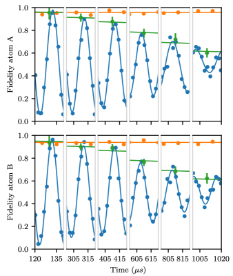
One of the most important properties of a quantum memory is the storage time that we test using the sequence. To this end, we vary the storage time between writing () and reading () of both atoms. The results for atom and atom are depicted in Fig. 2. Both atoms exhibit a coherence time of more than for linear polarisations and no measurable decay of the fidelity for circular polarisations. As in the single-atom case, the coherence time is limited by magnetic-field fluctuations on the few mG level. In addition, the coherence time is reduced by spatially sampling the locally varying magnetic field. Indeed, the margin on the atom positions is chosen in a way to have a reasonable data rate (see Supplement for further details). It is worth noting, that we expect no degradation of the coherence time for an even larger number of atoms as both atoms sample already a reasonably large region of the cavity mode.
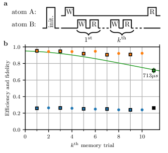
An extended case of the scenario is presented in Fig. 3.
Here, atom is used multiple times during the storage of atom .
This tests the cross talk for systems where many qubits are stored and retrieved serially on a single atom as shown here and also for future implementations where the number of atoms is scaled up even further.
Additionally it demonstrates that each atom can be used multiple times without re-initialization, allowing for higher repetition rates and potentially eliminating the need for atom-selective initialization.
In orange and blue, Figure 3b shows the achieved fidelity and efficiency, respectively, for the reused atom as a function of number of trials.
Efficiency and fidelity decay by and per trial as predicted by theory (see Supplement).
Figure 3b also shows the efficiency and fidelity of atom after the 10 memory trials on atom .
Although only about of the trials resulted in a successful memory event, in every trial the cavity is populated and the classical control field is applied, potentially leading to cross talk as discussed above.
Nevertheless, as the achieved fidelity is in good agreement with the expectation from the coherence-time measurement (green guide to the eye), any cross talk can be neglected even after 10 trials.
OUTLOOK
We have demonstrated an efficient network-ready random-access multi-qubit memory using two individually addressable single atoms.
We have identified and solved multiple challenges such as qubit cross talk which arise when making the most important step from one to several atoms in the same high-finesse optical cavity.
Given a lower bound on the store-and-retrieve efficiency of and a cavity mode waist of , up to 5 atoms can be accommodated.
We estimate that this number can be easily increased to more than 20 atoms while still using the same trapping geometry, e.g. by using a tighter focus of the addressing beam while still using the same objective. As all of those atoms would still be coupled to the same cavity mode, cavity-mediated multi-qubit gates 32; 28 enable computation on all of them.
For future implementations, deterministic and thus zero-tolerance atom positioning, as can be achieved in optical tweezer arrays 33; 34, would further increase capacity, data rate and fidelity.
Also, it would allow for Zeeman selective coherent driving addressed onto single atoms, resulting in more than coherence time 20.
In combination with atom-photon entanglement and atom-atom gates 19; 28, the extension to multiple individually addressable atoms renders the cavity platform a promising candidate for future quantum networks with quantum repeaters 7 and distributed quantum computers 9.
DATA AVAILABILITY
The data that support the findings of this study are available from the authors upon request.
ACKNOWLEDGEMENTS
We thank A. Neuzner and S. Ritter for contributions during the early stage of the experiments.
This work was supported by the Bundesministerium für Bildung und Forschung via the Verbund Q.Link.X (16KIS0870), by the Deutsche Forschungsgemeinschaft under Germany’s Excellence Strategy – EXC-2111 – 390814868, and by the European Union’s Horizon 2020 research and innovation programme via the project Quantum Internet Alliance (QIA, GA No. 820445).
AUTHOR CONTRIBUTIONS All authors conceived the experiment. Experimental data were taken by S.L., O.M. and M.K.. The manuscript was written by S.L., O.M. and G.R., with input from all authors.
References
- [1] Wootters, W. K. and Zurek, W. H. A single quantum cannot be cloned. Nature 299, 802–803 (1982).
- [2] Zhang, Q., Xu, F., Chen, Y.-A., Peng, C.-Z., and Pan, J.-W. Large scale quantum key distribution: challenges and solutions. Opt. Express 26, 24260–24273 (2018).
- [3] Yin, J. et al. Entanglement-based secure quantum cryptography over 1,120 kilometres. Nature 582, 501–505 (2020).
- [4] Kimble, H. J. The quantum internet. Nature 453, 1023–1030 (2008).
- [5] Wehner, S., Elkouss, D. and Hanson, R. Quantum internet: A vision for the road ahead. Science 362, eaam9288 (2018).
- [6] van Enk, S. J., Cirac, J. I. and Zoller, P. Ideal Quantum Communication over Noisy Channels: A Quantum Optical Implementation. Phys. Rev. Lett. 78, 4293 (1997).
- [7] Briegel, H.-J., Dür, W., Cirac, J. I. and Zoller, P. Quantum Repeaters: The Role of Imperfect Local Operations in Quantum Communication. Phys. Rev. Lett. 81, 5932 (1998).
- [8] Childress, L., Taylor, J. M., Sørensen, A. S. and Lukin, M. D. Fault-tolerant quantum communication based on solid-state photon emitters. Phys. Rev. Lett. 96, 070504 (2006).
- [9] Jiang, L., Taylor, J. M., Sørensen, A. S. and Lukin, M. D. Distributed quantum computation based on small quantum registers. Phys. Rev. A 76, 1–22 (2007).
- [10] DiVincenzo, D. P. The Physical Implementation of Quantum Computation Fortschr. Phys. 48, 9-11 (2000).
- [11] Landauer, R. Is Quantum Mechanics Useful? Philos. Trans. Royal Soc. A 353, 367–376 (1995).
- [12] Sinclair, N. et al. Spectral Multiplexing for Scalable Quantum Photonics using an Atomic Frequency Comb Quantum Memory and Feed-Forward Control. Phys. Rev. Lett. 113, 053603 (2014).
- [13] Tang, J.-S. et al. Storage of multiple single-photon pulses emitted from a quantum dot in a solid-state quantum memory. Nat. Commun. 6, 8652 (2015).
- [14] Laplane, C. et al. Multiplexed on-demand storage of polarization qubits in a crystal New J. Phys. 18, 013006 (2016).
- [15] Tiranov, A. et al. Temporal Multimode Storage of Entangled Photon Pairs. Phys. Rev. Lett. 117, 240506 (2016).
- [16] Jiang, N. et al. Experimental realization of 105-qubit random access quantum memory. Npj Quantum Inf. 5, 1 (2019).
- [17] Li, C. et al. Quantum Communication between Multiplexed Atomic Quantum Memories. Phys. Rev. Lett. 124, 240504 (2020).
- [18] Saffman, M., Quantum computing with atomic qubits and Rydberg interactions: progress and challenges. J. Phys. B: At. Mol. Opt. Phys. 49, 202001 (2016).
- [19] Reiserer, A. and Rempe, G. Cavity-based quantum networks with single atoms and optical photons. Rev. Mod. Phys. 87, 1379–1418 (2015).
- [20] Körber, M. et al. Decoherence-protected memory for a single-photon qubit. Nat. Photonics 12, 18–21 (2018).
- [21] Wilk, T. et al. Entanglement of Two Individual Neutral Atoms Using Rydberg Blockade. Phys. Rev. Lett. 104, 010502 (2010).
- [22] Kaufman, A. M. et al. Entangling two transportable neutral atoms via local spin exchange. Nature 527, 208–211 (2015).
- [23] Weiss, D. S. and Saffman, M. Quantum computing with neutral atoms. Phys. Today 70, 44–50 (2017).
- [24] Levine, H. et al. Parallel Implementation of High-Fidelity Multiqubit Gates with Neutral Atoms. Phys. Rev. Lett. 123, 170503 (2019).
- [25] Bruzewicz, C. D., Chiaverini, J., McConnell, R. and Sage, J. M. Trapped-ion quantum computing: Progress and challenges. Appl. Phys. Rev. 6, 021314 (2019).
- [26] Casabone, B. et al. Enhanced Quantum Interface with Collective Ion-Cavity Coupling. Phys. Rev. Lett. 114, 023602 (2015).
- [27] Inlek, I. V., Crocker, C., Lichtman, M., Sosnova, K. and Monroe, C. Multi-Species Trapped Ion Node for Quantum Networking. Phys. Rev. Lett. 118, 250502 (2017).
- [28] Welte, S., Hacker, B., Daiss, S., Ritter, S. and Rempe, G. Photon-Mediated Quantum Gate between Two Neutral Atoms in an Optical Cavity. Phys. Rev. X 8, 011018 (2018).
- [29] Nunn, J. et al. Multimode Memories in Atomic Ensembles. Phys. Rev. Lett. 101, 260502 (2008).
- [30] Neuzner, A., Körber, M., Morin, O., Ritter, S. and Rempe, G. Interference and dynamics of light from a distance-controlled atom pair in an optical cavity. Nat. Photonics 10, 303–306 (2016).
- [31] Morin, O., Körber, M., Langenfeld, S. and Rempe, G. Deterministic Shaping and Reshaping of Single-Photon Temporal Wave Functions. Phys. Rev. Lett. 123, 133602 (2019).
- [32] Borregaard J., Kómár P., Kessler E. M., Sørensen A. S., and Lukin, M. D. Heralded Quantum Gates with Integrated Error Detection in Optical Cavities. Phys. Rev. Lett. 114, 110502 (2015).
- [33] Endres, M. et al. Atom-by-atom assembly of defect-free one-dimensional cold atom arrays. Science 354, 1024–1027 (2016).
- [34] Barredo, D., Lienhard, V., de Léséleuc, S., Lahaye, T. and Browaeys, A. Synthetic three-dimensional atomic structures assembled atom by atom. Nature 561, 79–82 (2018).
Supplemental Material:
A network-ready random-access qubits memory
S. Langenfeld, O. Morin, M. Körber, and G. Rempe
Max-Planck-Institut für Quantenoptik, Hans-Kopfermann-Strasse 1, 85748 Garching, Germany
Supplementary Notes
S1 Setup
S1.1 Trapping and Sequence
Atoms are loaded into a two-dimensional (2D) standing wave trap, consisting of a blue-detuned () intra-cavity trap (y-axis) and a red-detuned () trap perpendicular to the cavity axis (-axis). The trap frequencies are for the (x,y,z)-axis. After loading, there is a random number of atoms () with random positions inside the cavity. The position of each atom is recorded via an imaging system consisting of an objective () and an EMCCD camera [1]. A pair of atoms with distance between and is selected (the choice of the atom positions is explained in the main text and discussed in Section S4). All other atoms are heated out of the trap by applying resonant light only onto these atoms via the optical addressing system (see Section S1.2). The selected pair is positioned symmetrically to the cavity center by shifting the red-detuned standing wave forming the trapping lattice and, along the blue-detuned intracavity trap axis, by (re)centering the atoms by decreasing and re-increasing the blue-detuned trap depth. The typical trapping time for two atoms is . Reloading of two atoms takes while only about 10% of the reloading attempts give a usable atomic pattern.
As soon as a usable pair of atoms is trapped, we perform the experimental sequence consisting of pumping to the initial ground state including Raman resolved sideband cooling to the motional ground state along the cavity axis (), qubit storage and retrieval. Afterwards we perform polarization gradient cooling to produce fluorescence light for the atom imaging and to extend the atom trapping time. Depending on the performed experiment, this sequence is repeated at a rate of .
S1.2 Optical addressing system
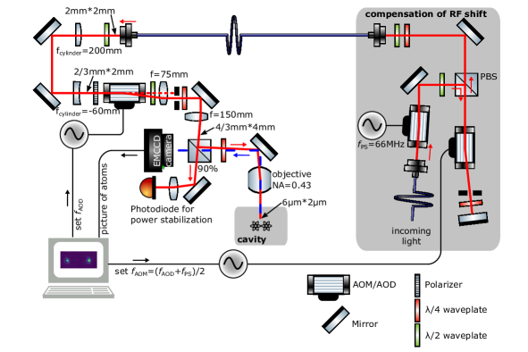
The optical and electronic setup is detailed in Fig. S1. The high-NA objective used for imaging the atoms is also used for applying light fields selectively onto single atoms. To this end, a non-polarizing beamsplitter (90:10) separates the track into imaging and addressing. After recording the position of the atoms to be addressed, the radio-frequency (RF) input of an acousto-optic deflector (AOD) is tuned so that its deflection aims on a specific atom. At the same time, the frequency of a preceding acousto-optical modulator (AOM) in a double-pass configuration is tuned so that it compensates the varying RF shift due to the AOD.
S2 Cross talk via the common cavity mode
As described in the main text and also the caption of Fig. 1 of the main text, one cross talk mechanism arises from the fact that both atoms are identically coupled to the same cavity field.
In one scenario, both atoms are initialized in and thus are ready to accept a photon. As described in the main text, even the not-addressed atom can interact with the cavity population via off-resonant scattering. Figure S2a depicts a tree of possible outcomes of an memory. At the different stages, either the write/read worked with probability , or if it didn’t work, there is a certain probability that the photon scattered to the additional (not-addressed-) atom. Figure S2b shows the derived fidelity and efficiency as a function of single photon detuning . The observed scaling is only possible because we were able to make almost detuning independent [2]. Thus, for all presented measurements, a detuning of , limited by available laser power, was chosen.
In a second scenario, the second, not-addressed, atom already successfully stores a qubit. Due to the large detuning of between the initial and the storage state, neither scattering nor ac-Stark shifts on the stored qubit contribute significantly.
S3 Cross-illumination
S3.1 Addressing beam profile
The addressing beam is used to apply light fields onto atoms which are distributed along the -axis and centered along the cavity- () axis. To this end, the width of this beam along the addressing axis should be significantly smaller than the expected atom-atom distance, which itself is upper limited by the cavity mode size of [1]. However, in order to be less susceptible to mechanical drifts of the setup, it is beneficial to have the addressing waist bigger than its theoretical minimum of . Here, we tuned the optical system to have a full width at half maximum (FWHM) in intensity of . As there is no addressing along the cavity () axis, the beam is elongated three-fold along this direction. This allows to accept a larger range of possible atom positions resulting in higher data rates. For further scaling to more atoms, there is no technological or physical reason not to have a narrower beam width in both dimensions.
S3.1.1 Intensity profile
In order to verify the intensity profile of the addressing beam as seen by the atom, we aim the addressing beam at a fixed position and probe the local intensity of the light by varying the atom position within. We apply resonant light on the cycling transition while having the cavity resonant with the same transition. The number of scattered photons picked up by the cavity and detected on a photon counter is linear in intensity for intensities small compared to the saturation intensity [3]. In green, Fig. S3a shows the number of clicks in arbitrary units as a function of a single atom’s position relative to the center of the addressing beam. As given above, the FWHM is . The center of the beam is at the aimed-at position, due to the calibration of atom-detection EMCCD-pixel and AOD RF-frequency.
S3.1.2 STIRAP profile
In the main text, only STIRAP control pulses are applied through the addressing system. As this is a non-linear process [4], the relevant addressing profile differs from the intensity profile. Here, we probe the profile again by aiming at a fixed position and changing the position of a single atom. In contrast to above, the cavity frequency is chosen in the same way as for the main text, i.e. resonant close to the transition. We globally prepare the storage state manifold and afterwards apply a read-out STIRAP pulse through the addressing system.
The amplitude and shape of the emitted photon depend on the temporal intensity profile of the applied STIRAP control pulse [4]. Thus, the read-out control pulse has to be optimized to not saturate the atom but still read most of the population. Figure S3a depicts the addressing profile for different read-out durations in different shades of blue. For a duration of (darkest blue), even a perfectly addressed atom cannot be read completely. In contrast, a (lightest blue) read-out duration gives a broadened, non-Gaussian profile of full amplitude. For the experiments demonstrated in the main text and this supplement, a read-out duration of (second darkest blue) was chosen, which gives a FWHM of while preserving almost completely the process efficiency.
S3.2 Minimum interatomic distance
Due to the finite size of the addressing beam, there has to be a minimum distance between the atoms so that cross-illumination is minimized. On the other side, the distance should be as small as possible to either allow for a larger acceptance range for possible positions and thus higher data rate, or in future implementations for a greater number of atoms in a volume limited by the cavity mode size. In order to get an application relevant bound for the interatomic distance, we perform a two-atom memory in the protocol. Here, opposite circular polarisations are stored on atom A and B to not be affected by the decoherence of linear polarisations and to have maximum infidelity in case of cross-illumination. Figure S3b shows the fidelity and efficiency of the read-out photons of atom A. For distances below about , the imaging system cannot resolve two separated atoms, so that there is no addressing possible for these configurations. Although this results in large error bars, the fidelity decreases significantly for interatomic distances below , in agreement with the addressing profiles presented above. For distances above , the fidelity approaches single-atom fidelities [5]. In contrast, the efficiency shows no clear trend and stays about constant within the investigated region. Due to these findings, all presented data is taken with a minimum distance of .
S4 Decoherence due to acceptance range of atomic positions
In the present scheme, atoms are loaded probabilistically into the two-dimensional trap inside the cavity. For single-atom protocols, the atom can be positioned within this trap to an accuracy of about . However, currently this positioning is limited to shifting all atoms in the trap simultaneously. For multi-atom protocols, this results in a shiftable center-of-mass, whereas the relative position of the atoms is given by the initial loading or subsequent jumps between lattice sites. In order to increase the data rate, a certain range of possible intermediate distances is accepted. As illustrated in Fig. S4a, this leads to a sampling of the intensity of the intra-cavity (blue-detuned) trap.
Due to circular components of the intra-cavity trap light, the atoms see a virtual magnetic field that depends on the intensity[1]. Figure S4b shows the relevant magnetic field as seen by the atom for a given position on the addressing axis. Depicted are two curves for two different ellipticities of the intra-cavity trap light. As the atoms sample a certain region and thus intensity, they are subject to a varying magnetic field environment, leading to a range of different precession Larmor frequencies, and thus to dephasing. In Fig. S4c, the theoretical decay in fidelity over time is presented for the two different mentioned ellipticities, assuming equal sampling of the acceptance range used for the experiments demonstrated in the main text. In the experiments presented in the main text, the situation labeled small ellipticity is used. For this configuration, Fig. S4c also shows the experimental result of the decay in fidelity as presented in the main text. Additionally, Fig. S4d shows the theoretical coherence time as a function of acceptance range of atomic positions. This clearly shows, that this is no fundamental limitation to the coherence time, as in principle the position of every atom could be fixed by e.g. employing an optical tweezer technique. Alternatively, the oscillation frequency could be feedback by the known position of the atoms or, as mentioned in the main text, the oscillation could be completely compensated by a rotating waveplate/electro-optical modulator.
S5 Extended scenario theory
Ideally, starting from the initial state , every write-read cycle ends again in the initial state. If this would be the case, every repeated write-read attempt would result in the same efficiency and fidelity. However, there are multiple experimental imperfections and physical side-effects which prevent this behavior.
We probe the memory with weak coherent pulses of average photon number . Due to losses of the cavity, about of the pulse do not interact with the atoms. At a single-photon detuning of , the scattering of the atom contributes by about . The branching ratio of the excited states leads to a decay to the initial state in of the cases. The remaining of the incoming photon are evenly shared by reflection of the pulse and successful storage in the desired atom.
The main shortcoming is the non-zero incoherent scattering probability of every STIRAP process due to the finite atom-light interaction rate . For every read-out attempt of a successful write-in, the finite results in a reduced probability of to go back to , whereas the remaining are distributed over , depending on the population of the storage states. Note that these decay processes do not contribute to the reported single-trial performance, as the cavity does not support the read-out photons of this polarization. Note that repeated read-out does not increase the efficiency, as the final state of every read-out attempt is in the manifold. Starting from one of the states , the next memory only performs with an efficiency of and an initial fidelity of , again depending on a combination of starting state and input polarization. This memory-trial again has some probability to end up in either the desired initial state , or in one of . Assuming the same probabilities as mentioned above, i.e. for returning to the initial state of this memory attempt, we set up a Markovian chain of events. Figure S5a shows a schematic summary of the described processes. Figure S5b presents the evolution of fidelity and efficiency versus the number of write-read attempts as experimentally demonstrated in the main text. There is a reasonable agreement between theory and experiment.
Supplementary References
- [1] Neuzner, A. Resonance Fluorescence of an Atom Pair in an Optical Resonator, PhD Thesis, TU München (2015).
- [2] Morin, O., Körber, M., Langenfeld, S. and Rempe, G. Deterministic Shaping and Reshaping of Single-Photon Temporal Wave Functions. Phys. Rev. Lett. 123, 133602 (2019).
- [3] Bochmann, J. et al. Lossless State Detection of Single Neutral Atoms. Phys. Rev. Lett. 104, 203601 (2010).
- [4] Gorshkov, A. V., Andre, A., Lukin, M. D. and Sørensen, A. S. Photon storage in -type optically dense atomic media. I. Cavity model. Phys. Rev. A 76, 033804 (2007).
- [5] Körber, M. et al. Decoherence-protected memory for a single-photon qubit. Nat. Photonics 12, 18–21 (2018).