Wireless Power Transfer with Distributed Antennas: System Design, Prototype, and Experiments
Abstract
In this paper, we design and experiment a far-field wireless power transfer (WPT) architecture based on distributed antennas, so-called WPT DAS, that dynamically selects transmit antenna and frequency to increase the output dc power. Uniquely, spatial and frequency diversities are jointly exploited in the proposed WPT DAS with low complexity, low cost, and flexible deployment to combat the wireless fading channel. A numerical experiment is designed to show the benefits using antenna and frequency selections in spatially and frequency selective fading channels for single-user and multi-user cases. Accordingly, the proposed WPT DAS for single-user and two-user cases is prototyped. At the transmitter, we adopt antenna selection to exploit spatial diversity and adopt frequency selection to exploit frequency diversity. A low-complexity over-the-air limited feedback using an IEEE 802.15.4 RF interface is designed for antenna and frequency selections and reporting from the receiver to the transmitter. The proposed WPT DAS prototype is demonstrated in a real indoor environment. The measurements show that WPT DAS can boost the output dc power by up to 30 dB in single-user case and boost the sum of output dc power by up to 21.8 dB in two-user case and broaden the service coverage area in a low cost, low complexity, and flexible manner.
Index Terms:
Antenna selection, distributed antennas, diversity, frequency selection, rectenna, wireless power transfer.I Introduction
THE Internet of Things (IoT) is envisioned to create an intelligent world where sensors, actuators, machines, humans, and other objects are connected so as to enhance the efficiencies, performances, and services in manufacturing, monitoring, transportation, and healthcare [1]. However, the IoT devices might be deployed in unreachable or hazard environment so that battery replacement or recharging becomes inconvenient. Moreover, replacing or recharging batteries of a large number of IoT devices is prohibitive and unsustainable. Therefore, it remains a challenging issue to power IoT devices in a reliable, controllable, user-friendly, and cost-effective manner. To overcome this issue, a promising technology is far-field wireless power transfer (WPT) via radio-frequency (RF) [2], [3]. Compared with near-field WPT via inductive coupling or magnetic resonance [4]-[6], far-field WPT utilizes a dedicated source to radiate RF energy through a wireless channel and a rectifying antenna (rectenna) to receive and convert this energy into direct current (dc) power so that it can transfer power over a long distance and broader coverage. A related technology to far-field WPT is ambient RF energy harvesting [7]-[10], which uses rectenna to receive RF energy from existing source such as cellular and WiFi system. However, ambient RF energy harvesting is less reliable and controllable than far-field WPT.
The major challenge of far-field WPT is to increase the output dc power of the rectenna without increasing the transmit power, and to broaden the service coverage area. To that end, the vast majority of the technical efforts in the literature have been devoted to the design of efficient rectenna. Techniques to enhance the rectenna design include using multiband rectenna [11], multiport rectenna [12], [13] or uniform rectenna array [14], dual-polarized rectenna [15], filtering antenna for harmonic rejection [16], reconfigurable rectifier [17], differential rectenna [18], hybrid RF-solar harvester [19], and electrical small rectenna [20], [21].
The various rectenna designs [11]-[21], however, ignored wireless fading channel which has a significant impact on far-field WPT performance. Due to multipath propagation and shadowing effect, wireless channel experiences fading that severely attenuates the received RF signal and subsequently limits the output dc power in far-field WPT. To combat wireless fading channel in far-field WPT, a promising approach is to exploit diversity, both in the spatial and frequency domains. Assuming the channel state information (CSI) can be acquired at the transmitter, simulations in [22] show that spatial diversity can be exploited by using adaptive beamforming to increase the output dc power in far-field WPT while simulations in [23] show that frequency diversity can be exploited by using adaptive waveform, and furthermore simulations in [24] show that spatial and frequency diversities can be jointly exploited by using adaptive beamforming and waveform simultaneously. Motivated by the simulation results in [22]-[24], several far-field WPT systems exploiting diversity have been designed and prototyped to increase the output dc power. In [25], [26], WPT systems with adaptive beamforming using receive signal strength indicator feedback were designed, and two other WPT systems with adaptive beamforming using Kalman filter were designed in [27], [28]. However, the WPT systems in [25]-[28] only exploited spatial diversity by using adaptive beamforming but did not consider exploiting frequency diversity. In [29], spatial diversity was exploited and demonstrated using a so-called transmit diversity technique that, in contrast to beamforming, does not rely on the knowledge of the CSI at the transmitter. A WPT system with adaptive waveform was designed to exploit the frequency diversity in [30], but it did not consider exploiting spatial diversity and it used a closed-loop cable feedback to report CSI which limits its practicability. In [31], a WPT architecture exploiting jointly spatial and frequency diversity was designed and experimented, however, it used the cable-based feedback and centralized processing, and did not address the practical and challenging problem of CSI acquisition at the transmitter.
In contrast with [22]-[31] which adopt co-located transmit antennas architecture, there is another important WPT architecture adopting distributed antenna system (DAS) at the transmitter, so-called WPT DAS, which is a more flexible architecture and provides a broader service coverage. Various aspects and scenarios of WPT DAS [32]-[37] and the related area of simultaneous wireless information and power transfer (SWIPT) with distributed antennas (SWIPT DAS) [38]-[46] have been considered and studied to increase the output dc power and the energy efficiency or minimize the transmit power, such as limited feedback design, multi-user, secure communications, and deployment optimization. However, there are two main limitations in [32]-[46]
1) All these works only consider exploiting spatial diversity to increase the output dc power, but none of them considers exploiting frequency diversity, which is actually very useful to increase the output dc power;
2) Almost all the works (except [37]) only have numerical simulation results, without any prototyping and experimental results to validate the design and the simulation results in real-world settings. As for the prototyping work in [37], the limitation is that it does not consider exploiting the frequency diversity to increase the dc power.
In contrast with the above works, in this paper we design, prototype, and experimentally validate an adaptive WPT DAS utilizing antenna and frequency selections to exploit the spatial and frequency diversities and increase the output dc power for single-user and multi-user cases. Our work has both theoretical and experimental contributions as summarized below.
Theoretical Contributions: we propose exploiting frequency diversity together with spatial diversity by antenna and frequency selections in WPT DAS to combat the wireless fading channel so as to significantly increase the output dc power. We also design a numerical experiment to demonstrate the benefits of exploiting spatial and frequency diversities by utilizing antenna and frequency selections in far-field WPT DAS in spatially and frequency selective fading channels for both single-user and multi-user cases.
Experimental Contributions: we devise, prototype, and experimentally verify the proposed WPT DAS for both single-user and multi-user cases with homemade rectifier and off-the-shelf hardware components. To the authors’ best knowledge, it is the first prototype of far-field WPT DAS utilizing antenna and frequency selections. Prototyping WPT DAS includes a lot of system engineering, ranging from frame structure design, rectenna design, device programming, and choosing proper hardware components. Besides, there are practical challenges to prototype WPT DAS exploiting spatial and frequency diversities including
1) It is expensive to use highly linear power amplifier (PA), especially using multiple PAs for multiple distributed antennas. Hence, it is challenging to exploit frequency diversity while keeping a low peak to average power ratio (PAPR) waveform to avoid using expensive PA.
2) Achieving accurate synchronizations among distributed transmit antennas requires complicated RF chains and centralized processing, which increase the complexity and cost and make the antenna deployment less flexible and the cooperation among transmit antennas difficult. Hence, it is challenging to exploit spatial diversity while using a simple and low cost architecture with de-centralized processing.
3) Acquiring accurate CSI at the multiple distributed antennas and operating frequencies is difficult and power consuming, especially for the multi-user case. Hence, it is challenging to jointly exploit spatial and frequency diversities without accurate CSI.
Our proposed WPT DAS prototype successfully exploits the spatial and frequency diversities while overcoming these challenges by utilizing antenna and frequency selections for single-user and multi-user cases. Particularly, through an experiment in a real indoor environment, we show that the proposed WPT DAS can significantly increase the output dc power by up to 30 dB in a single-user case and increase the sum of output dc power by up to 21.8 dB in a two-user case, compared with conventional WPT DAS without any selection. Moreover, the proposed WPT DAS prototype also has multiple benefits including
1) It does not require expensive highly linear power amplifiers since it relies on simple transmit antennas fed with a low PAPR continuous wave, so the cost of system is decreased.
2) It does not require accurate synchronization since only one antenna/frequency at a time is activated, so that the RF chain complexity and cost are reduced.
3) It does not require centralized processing for the distributed antenna system, so that the deployment of distributed antennas becomes more flexible.
4) It does not require channel estimation to achieve accurate CSI. It can exploit the spatial and frequency diversities through a low complexity over-the-air limited feedback using an IEEE 802.15.4 RF interface.
5) Its antenna and frequency selection strategy exploits the natural disparity of channel strengths between the different transmit antennas and receiver using a minimum architecture.
6) It is applicable and beneficial in multi-user deployments. It can effectively increase the sum of output dc power through limited feedback without requiring accurate CSI.
To conclude, this paper experimentally shows that we can achieve significant performance gains in WPT DAS for both single-user and multi-user cases with low cost, low complexity, flexible deployment, and without requirement of accurate CSI, by using off-the-shelf hardware components. This is essential for the wide acceptance of WPT in industrial applications.
This paper is organized as follows. Section II describes a WPT system model with antenna and frequency selections. Section III provides a numerical experiment showing the benefits of antenna and frequency selections. Section IV provides the adaptive WPT DAS design utilizing antenna and frequency selections. Section V provides the experimental results. Section VI provides the prototyping and measurement of the two-user WPT DAS. Section VII concludes the work.
II WPT System Model
We propose a WPT DAS utilizing antenna and frequency selections. The transmitter is equipped with antennas which are distributed at different locations and the receiver is equipped with an antenna and a rectifier. The transmitter sends a continuous sinewave to the receiver, whose frequency is selected from available operating frequencies , …, within the bandwidth of the WPT system. When the th operating frequency in the th transmit antenna is activated, the transmitted signal can be expressed as
| (1) |
where denotes the transmit power. The transmitted signal propagates through a multipath channel between the th transmit antenna and the receive antenna, which is characterized by paths whose delay, amplitude, and phase are respectively denoted as , , and . Therefore, the received signal is represented by
| (2) |
where the amplitude and the phase are such that
| (3) |
Hence, the received RF power is given by . The received RF power is converted into dc power by the rectifier. For a continuous wave, the RF-to-dc conversion efficiency of the rectifier, denoted as , is a nonlinear function of its input RF power , which increases with until a turning point after which decreases because of the diode breakdown effect. Therefore, the output dc power is given by
| (4) |
For different transmit antennas , the amplitudes , …, exhibit different values due to the different multipath propagations (, , and ) between the distributed transmit antennas and the receiver. In addition, given the th transmit antenna, the amplitudes , …, exhibit different values for different operating frequencies , …, , which is referred to as frequency selective fading channel. Hence, varies with activating different transmit antennas and different operating frequencies. Namely, activating different transmit antennas and operating frequencies provides spatial diversity and frequency diversity in respectively. Therefore, we can exploit such spatial and frequency diversities by selecting the optimal transmit antenna and operating frequency to maximize the output dc power, i.e.
| (5) |
Compared with the far-field WPT system without exploiting any diversity, i.e. and , the proposed WPT DAS using antenna and frequency selections can achieve higher output dc power because it exploits spatial and frequency diversities by adaptively selecting the optimal transmit antenna and operating frequency.
In the next section, we design a numerical experiment to show the benefits of the proposed WPT DAS architecture.
III WPT DAS Simulations
We design a numerical experiment to simulate the output dc power of the proposed WPT DAS utilizing antenna and frequency selections. The simulations consider a typical large open space indoor (or outdoor) WiFi-like environment at a central frequency of 2.4 GHz with 75 MHz bandwidth. The operating frequencies , …, are uniformly spaced within the bandwidth. The transmit antennas are distributed at different locations therefore the channels are modeled to be independent to each other. The power delay profile of the IEEE TGn NLOS channel model E [47] is used to generate the frequency selective fading channel. The transmit power is set as 36 dBm. The path loss is set as 60.046 dB (for a distance of 10 m with 0 dBi transmit/receive antenna gains). A single diode rectifier is considered in the simulations. It is also fabricated and used to construct the proposed far-field WPT DAS prototype. More details including the circuit topology and measured RF-to-dc efficiency of the single diode rectifier are provided in Section IV.
The simulations are performed in the software MATLAB according to the following steps. 1) We generate random frequency selective fading channels using IEEE TGn NLOS channel model E; 2) We activate the different transmit antennas and different operating frequencies one-by-one to find the corresponding received RF power; 3) With the measured RF-to-dc efficiency of the rectifier at different input RF power levels and at different frequencies, we can find the corresponding output dc power; and 4) We select the optimal transmit antenna and operating frequency to achieve the maximum output dc power as per (5). We use Monte Carlo method to run 300 times the simulation for different channel realizations so as to find the average output dc power of the proposed WPT DAS.
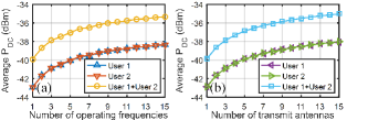
The simulation results are plotted in Fig. 1. First, we show the simulated average output dc power versus the number of operating frequencies at a fixed transmit antenna in Fig. 1(a). We can find that the average increases with , showing the benefit of frequency selection. Next, we show the simulated average output dc power versus the number of transmit antennas at a fixed operating frequency in Fig. 1(b). We can find that the average increases with , showing the benefit of antenna selection. Finally, we show the simulated average output dc power utilizing no selection, frequency selection only, antenna selection only, and antenna and frequency selections with different in Fig. 1(c). We can find that the joint antenna and frequency selections achieve higher average output dc power than the frequency or antenna selection only and no selection, showing the benefit of joint antenna and frequency selections over frequency or antenna selection only and no selection in WPT DAS.
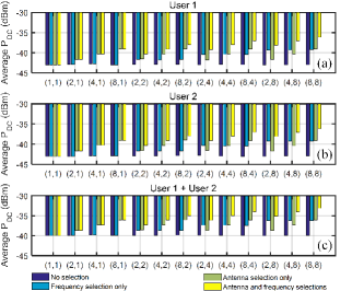
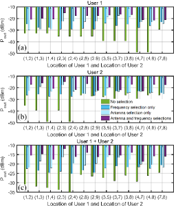
Our proposed WPT DAS utilizing antenna and frequency selections also works for the multi-user/receiver case. We use time-division multiple access (TDMA) for the multiple users in the proposed WPT DAS, i.e. antenna and frequency selections are performed alternatively for each user at each time frame. The simulation results for a two-user WPT DAS utilizing antenna and frequency selections with TDMA is shown in Fig. 2 and Fig. 3. From Fig. 2, we can find that the average for User 1 and User 2 are the same due to their same channel statistics, and the sum of average of two users increases with the number of operating frequencies and transmit antennas, showing the benefit of antenna selection and frequency selection. Furthermore, from Fig. 3, we can find that the joint antenna and frequency selections achieve higher sum of average of two users than the frequency or antenna selection only and no selection, showing the benefit of joint antenna and frequency selections over frequency or antenna selection only and no selection in two-user case. Besides, the average for User 1 and User 2 is again shown to be the same in Fig. 3. The same conclusion and validation can also be drawn for the case of a larger number of users.

IV WPT DAS Design
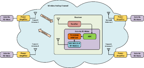
Motivated by the numerical experiment results, we devise an adaptive WPT DAS utilizing antenna and frequency selections which exploits spatial and frequency diversities to increase the output dc power. The schematic diagram of the proposed far-field WPT system is shown in Fig. 4.
IV-A Transmitter Design
Distributed antennas are used at the transmitter. There are four monopole antennas distributed at different locations, e.g. four corners in an indoor room. The four monopole antennas are identical, which resonate at 2.4 GHz and have an omni-directional radiation pattern with 3 dBi antenna gain and 85% radiation efficiency. Each antenna is connected to a power amplifier, Mini-Circuits ZHL-16W-43-S+, which has a gain of 45 dB and amplifies the RF signal generated by a Zolertia RE-Mote. The transmit power is set to 36 dBm (4W), which is safe for human beings to use. The measured output dc power shown in Section V also confirms the safety for human beings. The Zolertia RE-Mote is a hardware development platform consisting of the Texas Instruments CC2538 ARM Cortex-M3 system on chip (SoC) and an on-board 2.4 GHz IEEE 802.15.4 RF interface. The photo of the Zolertia RE-Mote is shown in Fig. 5. In the Zolertia RE-Mote, we use a Contiki operating system as a software platform.
The Zolertia RE-Mote in the transmitter is not only used to generate RF signal for WPT, but also used to communicate with the receiver which is also equipped with a Zolertia RE-Mote. The receiver sends messages to the transmitter through Zolertia RE-Mote for activating different transmit antennas and operating frequencies. In addition, the Zolertia RE-Mote in the receiver also selects the best transmit antenna and operating frequency and then reports the selection to the transmitter so as to increase the output dc power. The 2.4 GHz IEEE 802.15.4 RF interface in the Zolertia RE-Mote specifies 16 channels within the 2.4-GHz band. The operating frequency for the th channel is MHz, . These operating frequencies are defined by IEEE 802.15.4 standard, which the Zolertia RE-Mote follows. The first 15 channels are used for WPT with frequency selection while the last channel is used for the communication between the transmitter and receiver, e.g. the receiver sending messages and feedback to the transmitter.
IV-B Receiver Design
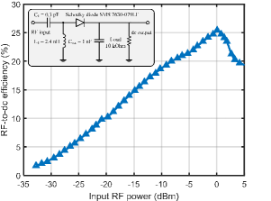
The receiver consists of two parts as shown in Fig. 5. The first part is a rectenna that receives RF signal and converts it to dc power. It consists of a single diode rectifier and 2.4-GHz monopole antenna with 3 dBi gain and 85% radiation efficiency. The topology of the single diode rectifier is shown in Fig. 6. We use the single diode topology due to its design and fabrication simplicity and good RF-to-dc conversion efficiency at a low RF input power level. The rectifier consists of an impedance matching network, a rectifying diode, a low pass filter, and a load. The Schottky diode Skyworks SMS7630 is chosen as the rectifying diode because it has a low turn-on voltage, which is suitable for low power rectifier. The values of the components in the matching network and low pass filter are optimized to maximize RF-to-dc conversion efficiency at the input RF power of -20 dBm. We use common materials including the 1.6-mm-thick FR-4 substrate and lumped elements to simplify the rectifier fabrication. The measured RF-to-dc efficiency of the single diode rectifier is shown in Fig. 6, which is used in the numerical simulation to find the average output dc power.
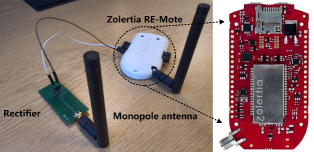
The second part is made up by a 2.4-GHz monopole antenna and a Zolertia RE-Mote, which is used to measure the output dc voltage of the rectenna and communicate with the transmitter. The Zolertia RE-Mote in the receiver sends messages to the transmitter to activate different transmit antennas and operating frequencies. It also sends feedback to the transmitter to report the antenna and frequency selections and then the optimal transmit antenna and operating frequency can be activated. The Zolertia RE-Mote measures the output dc voltage of the rectifier through a built-in analog-to-digital converter (ADC). The CC2538 ARM Cortex-M3 SoC in the Zolertia RE-Mote processes the measured output dc voltages and generate a feedback which is sent to the transmitter through the built-in IEEE 802.15.4 RF interface.
IV-C Flow Chart
The flow chart of the adaptive WPT DAS utilizing antenna and frequency selections is shown in Fig. 7. The transmitter and receiver cooperatively work frame by frame. Each frame has two phases: training phase and WPT phase. The training phase is to find the optimal transmit antenna and operating frequency while the WPT phase is to transmit the RF signal with the optimal transmit antenna and operating frequency.
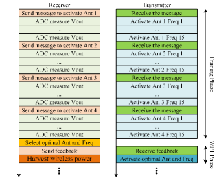
In the training phase, the receiver first broadcasts a message to the four distributed transmit antennas in the transmitter through the built-in IEEE 802.15.4 RF interface of Zolertia RE-Mote. The message content is to activate the transmit antenna 1 so that the transmit antenna 1 will start to work and the other three transmit antennas will keep idle. When the transmit antenna 1 is active, it will transmit RF signal with operating frequency , , …, and in turn. The time duration for transmitting RF signal at each operating frequency is . In the meantime, the receiver will measure and record the corresponding output dc voltage of the rectenna at each operating frequency through the built-in ADC in Zolertia RE-Mote. Then, the receiver broadcasts messages to activate the transmit antennas 2, 3, 4 in turn. Each active transmit antenna will transmit RF signal with operating frequency , , …, and in turn and the receiver will measure and record the corresponding output dc voltage in the meantime. By this way, the Zolertia RE-Mote in the receiver collects the output dc voltage with activating different transmit antennas and operating frequencies so that it can find the optimal transmit antenna and operating frequency to maximize the output dc voltage. Since there are combinations of transmit antenna and operating frequency, the receiver only needs 6 bits (rounding ) to index the optimal transmit antenna and operating frequency and then sends a feedback containing these bits to the transmitter through the IEEE 802.15.4 RF interface. By this way, we can implement a limited feedback over the air with low complexity to achieve partial CSI at the transmitter. Finally, with the partial CSI, the transmitter can switch to the optimal transmit antenna and operating frequency. The time duration for the training phase is . is dependent on the clock and timer setup in Zolertia RE-Mote, which can be modified by programming. We can set a smaller in Zolertia RE-Mote to accelerate the training phase, however, cannot be too small because the output dc voltage for a given transmit antenna and operating frequency needs some time to be stable for ADC sampling. If is very small, the output dc voltage is not stable, the dc voltage sampled by ADC is not accurate, and the optimal transmit antenna and operating frequency cannot be selected.
In the WPT phase, the transmitter transmits the RF signal with the optimal transmit antenna and operating frequency. In the meantime, the receiver harvests the wireless power. The time duration for the WPT phase is . When the WPT phase is over, it goes to the next frame so that the time duration for one frame is given by . Therefore, every four seconds, the proposed WPT system periodically adapts to the wireless fading channel to achieve the maximum output dc power.
V WPT DAS Experiment
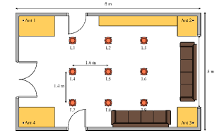
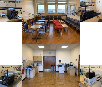
To verify the proposed adaptive WPT DAS utilizing antenna and frequency selections, we prototype and measure it in a indoor environment. As illustrated in Fig. 8, the indoor environment is equipped with common facilities such as chairs, tables, and sofas so that multipath fading exists in the wireless channel. The four transmit antennas are distributed at the four corners of the room. The receiver is placed at different locations marked as L1, L2, …, and L9 in order to measure the performance of the proposed adaptive WPT DAS at different locations. The photos of the proposed WPT DAS measurement in an indoor environment are shown in Fig. 9.
We use an oscilloscope to measure the output dc voltage of the rectenna, denoted as , at different locations. The output dc voltage waveform in one frame at different locations are plotted in Fig. 10. We make the following observations.
1) We find that the frame consists of two phases, training phase and WPT phase, which confirms the designed flow chart of the proposed WPT system as shown in Section IV. During the training phase, the output dc voltage changes over time since the transmit antennas 1-4 are activated in turn and the operating frequency , , …, and are activated in turn for each active transmit antenna. During the WPT phase, the output dc voltage are constant and highest over time since the transmitter transmits the RF signal with the optimal transmit antenna and operating frequency.
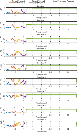
2) We find that for any transmit antenna at any location, the output dc voltage changes with the operating frequencies , , …, and , which demonstrates that the wireless channel in WPT system is frequency selective. By utilizing frequency selection, the frequency diversity can be exploited to overcome the frequency selective fading and increase the output dc power.
3) We find that given any operating frequency at any location the output dc voltage changes with the transmit antenna. This is because the multipath propagation between the distributed transmit antennas and receiver changes with different locations. By selecting the preferred transmit antennas, the spatial diversity can be exploited to overcome the fading and increase the output dc power.
We also quantitatively show the benefits of frequency selection, antenna selection, and the joint antenna and frequency selections in the proposed WPT system.
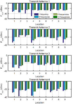
First, we show the benefit of frequency selection only. To that end, we use 1 transmit antenna and only utilize frequency selection with different numbers of operating frequencies. The measured output dc power, denoted as in the remainder of this paper, versus the number of operating frequencies with different transmit antennas at different locations is shown in Fig. 11. In particular, we consider four cases: 1 operating frequency , 3 operating frequencies , , , 5 operating frequencies , , , , , and 15 operating frequencies , , …, and . We find that the output dc power increases with the number of operating frequencies with different transmit antennas and locations. It should be noted that, at some locations, the output dc power is constant even though we increase the number of operating frequencies, e.g. L6 with transmit antenna 1. This is because is already the optimal operating frequency. Overall, the measurement results in Fig. 11 demonstrate the benefit of utilizing frequency selection in WPT system to increase the output dc power.
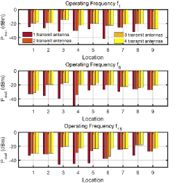
Next, we show the benefit of antenna selection only. To that end, we use 1 operating frequency and only utilize antenna selection with different numbers of transmit antennas. The measured output dc power versus the number of transmit antennas with different operating frequencies (, , and ) at different locations is shown in Fig. 12. We find that the output dc power increases with the number of transmit antennas with different operating frequencies and locations. Similarly, it should be noted that, at some locations, the output dc power is constant even though we increase the number of transmit antennas, e.g. L9 with . This is because transmit antenna 1 is already the optimal transmit antenna. Overall, the measurement results in Fig. 12 demonstrate the benefit of utilizing antenna selection to increase the output dc power. In addition, we can deduce that given an acceptable output dc power utilizing antenna selection for distributed antennas can broaden the service coverage area.
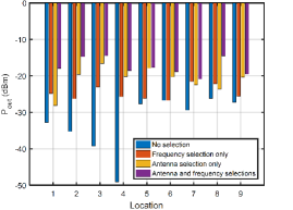
Finally, we show the benefit of joint antenna and frequency selections. To that end, we compare the proposed WPT DAS utilizing antenna and frequency selections with WPT systems with no selection, frequency selection only (fixed 1 transmit antenna), and antenna selection only (fixed 1 operating frequency). The measured output dc power at different locations is shown in Fig. 13. We can find that the joint antenna and frequency selections achieves higher output dc power than frequency or antenna selection only and no selection. Particularly, compared with the conventional WPT system without any selection, the proposed WPT DAS utilizing antenna and frequency selections can achieve 7.7-30.5 dB more output dc power. Therefore, the measurement results demonstrates the benefit of joint exploiting spatial and frequency diversities by antenna and frequency selections in far-field WPT DAS, and it should be noted that such benefit in output dc power is achieved in a low cost, low complexity, and flexible manner.
We provide a power budget analysis to show the available dc energy and the power consumption of the receiver (mainly from Zolertia RE-Mote). Discussion on how to use such available dc energy for practical applications is also provided.
First, we estimate the available dc energy achieved by the rectenna in one frame. In the training phase (), the output dc power changes with different transmit antennas and operating frequencies. The average output dc power during the training phase (over 9 locations, 4 transmit antennas, and 15 operating frequencies) is . On the other hand, in the WPT phase (), the output dc power is constant over time and is maximized by selecting the optimal transmit antenna and operating frequency. The average output dc power during the WPT phase (over 9 locations) is . So the total available dc energy in one frame ( ) is .
Next, we estimate the dc energy consumed by the Zolertia RE-Mote in one frame. It is hard to measure the power consumed by different modules in the Zolertia RE-Mote since all the modules are integrated together. As a compromise, we can only calculate the power consumption according to the data sheet. Specifically, the CC2538 ARM Cortex-M3 SoC in the Zolertia RE-Mote can work in a low power mode with power consumption of , so the corresponding consumed dc energy in one frame is . Besides, the IEEE 802.15.4 RF interface in the Zolertia RE-Mote consumes some dc energy to send messages and feedback with a power consumption . In one frame, the receiver sends four messages and one feedback to the transmitter so that the total data size is 5 bytes (the data size for one message or feedback is one byte). The data rate of the 802.15.4 RF interface is 250 kbps so that the RF interface will work for in one frame and the consumed dc energy is . So the Zolertia RE-Mote consumed in total in one frame.
Finally, we can estimate that the net available dc energy in one frame is , so that the efficiency is . In spite of the power consumption, using antenna and frequency selections is still beneficial compared with conventional WPT DAS design without any selection. Here in the test we use a battery to power the Zolertia RE-Mote to simplify the receiver architecture, as the purpose of the paper is primarily to show the benefit of antenna and frequency selections in WPT DAS. Using a battery does not affect the key conclusion that using antenna and frequency selections increases the output dc power in WPT DAS. A more practical receiver architecture would be using a power management unit to store the net available dc energy and provide a suitable dc voltage for powering Zolertia RE-Mote and low power low duty-cycle sensors in the IoT [7], [48], [49]. Furthermore, it is worth noting that IoT power consumption is decreasing, with the power demand for microprocessor unit, sensor unit and the wireless link continuously reducing over the years. Hence, the proposed WPT DAS is expected to be found in more applications in the near future.
We also provide the power consumption of the transmitter. The power amplifier is power by a 28 V dc supply with a current of 3 A, so its power consumption is 84 W. The power consumption of Zolertia RE-Mote at the transmitter has two parts. The first part is from the RF interface, which is used to generate the transmit signal, and it has a power consumption of 48 mW. The second part is from the SoC, which is used for control and processing, and it has a power consumption of . The monopole antenna is a passive device and it has a radiation efficiency of 85%. Overall, the power consumption of the transmitter is mainly from the power amplifier.
VI Generalization to Two-User WPT DAS
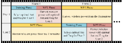
To show that our proposed WPT DAS utilizing antenna and frequency selections also works for the multi-user case, we have prototyped a two-user WPT DAS with TDMA as illustrated in Fig. 14. In Frame 1, the antenna and frequency selections are performed only for User 1, following the same flow chart of the single-user WPT DAS as shown in Fig. 7, while User 2 only harvests the wireless power from the transmitter without doing anything else. In Frame 2, the antenna and frequency selections are performed only for User 2 while User 1 only harvests the power without doing anything else. By this way, the antenna and frequency selections are alternatively performed for each user at each frame.
Following the same experimental settings of the single-user WPT DAS in Section V, we place User 1 and User 2 at different locations, L1-L9 as shown in Fig. 8, and measure the output dc power of User 1, User 2, and the sum of output dc power of User 1 and User 2. The measurement results are shown in Fig. 15. From Fig. 15, we can find that using antenna and frequency selections can effectively increase the output dc power of User 1 and User 2 and sum compared with antenna or frequency selection only and no selection at different locations. Particularly, compared with conventional two-user WPT DAS without any selection, using antenna and frequency selection can increase the sum of output dc power by 8.6-21.8 dB. Therefore, it demonstrates our approach of using antenna and frequency selections is valid and beneficial for two-user case. Besides, using TDMA in WPT DAS is also applicable and beneficial for a larger number of users.
VII Conclusions
We design, prototype, and experimentally validate an adaptive WPT DAS utilizing antenna and frequency selections to significantly increase the output dc power for both single-user and multi-user cases in a low cost, low complexity, and flexible manner. Spatial and frequency diversities are jointly exploited by antenna and frequency selections in the proposed WPT DAS to combat the wireless fading channel and increase the output dc power.
We design a numerical experiment to show the benefits of exploiting spatial and frequency diversities using antenna and frequency selections with frequency selective Rayleigh fading channel for single-user and multi-use cases. Accordingly, the proposed WPT DAS for single-user and two-user cases is prototyped. Four transmit antennas are placed at four corners of an indoor room and antenna selection is used to exploit spatial diversity. Besides, we adopt frequency selection at the transmitter to exploit frequency diversity. We also devise a limited feedback over the air (through an IEEE 802.15.4 RF interface) with low complexity to achieve partial CSI.
The proposed far-field WPT DAS system prototype is demonstrated in a real indoor environment. The measurement results confirm the fading channel in WPT and show that the output dc power can be increased by antenna and frequency selections for both single-user and multi-user cases.
In summary, this paper experimentally shows that we can achieve significant performance gains in WPT DAS for single-user and multi-user cases with low cost, low complexity, flexible deployment, and without requirement for accurate CSI, by using off-the-shelf hardware components. This is essential for the wide acceptance of WPT in industrial applications.
References
- [1] M. Zorzi, A. Gluhak, S. Lange, and A. Bassi, “From today’s intranet of things to a future internet of things: a wireless-and mobility-related view,” Wireless Communications, IEEE, vol. 17, no. 6, pp. 44–51, Jun. 2010.
- [2] C. Song et al., “Matching network elimination in broadband rectennas for high-efficiency wireless power transfer and energy harvesting,” IEEE Trans. Ind. Electron., vol. 64, no. 5, pp. 3950–3961, May 2017.
- [3] Z. Du and X. Y. Zhang, “High-efficiency single- and dual-band rectifiers using a complex impedance compression network for wireless power transfer,” IEEE Trans. Ind. Electron., vol. 65, no. 6, pp. 5012–5022, June 2018.
- [4] J. Acero, C. Carretero, I. Lope, R. Alonso, O. Lucia, and J. M. Burdio, “Analysis of the mutual inductance of planar-lumped inductive power transfer systems,” IEEE Trans. Ind. Electron., vol. 60, no. 1, pp. 410–420, Jan 2013.
- [5] S. Yu, H. Liu, and L. Li, “Design of near-field focused metasurface for high-efficient wireless power transfer with multifocus characteristics,” IEEE Trans. Ind. Electron., vol. 66, no. 5, pp. 3993–4002, May 2019.
- [6] Z. Zhang, H. Pang, A. Georgiadis, and C. Cecati, “Wireless power transfer - an overview,” IEEE Trans. Ind. Electron., vol. 66, no. 2, pp. 1044–1058, Feb 2019.
- [7] A. E. Abdulhadi and R. Abhari, “Multiport UHF RFID-tag antenna for enhanced energy harvesting of self-powered wireless sensors,” IEEE Trans. Ind. Electron., vol. 12, no. 2, pp. 801–808, April 2016.
- [8] C. Song et al., “A novel quartz clock with integrated wireless energy harvesting and sensing functions,” IEEE Trans. Ind. Electron., vol. 66, no. 5, pp. 4042–4053, May 2019.
- [9] L. Guo, X. Gu, P. Chu, S. Hemour, and K. Wu, “Collaboratively harvesting ambient radiofrequency and thermal energy,” IEEE Trans. Ind. Electron., pp. 1–1, 2019.
- [10] S. Shen, Y. Zhang, C. Chiu, and R. Murch, “A triple-band high-gain multibeam ambient RF energy harvesting system utilizing hybrid combining,” IEEE Trans. Ind. Electron., vol. 67, no. 11, pp. 9215–9226, 2020.
- [11] C. Song, Y. Huang, P. Carter, J. Zhou, S. Yuan, Q. Xu, and M. Kod, “A novel six-band dual CP rectenna using improved impedance matching technique for ambient RF energy harvesting,” IEEE Trans. Antennas Propag., vol. 64, no. 7, pp. 3160–3171, July 2016.
- [12] S. Shen, C. Y. Chiu, and R. D. Murch, “A dual-port triple-band L-probe microstrip patch rectenna for ambient RF energy harvesting,” IEEE Antennas Wireless Propag. Lett., vol. 16, pp. 3071–3074, 2017.
- [13] S. Shen, C. Y. Chiu, and R. D. Murch, “Multiport pixel rectenna for ambient RF energy harvesting,” IEEE Trans. Antennas Propag., vol. 66, no. 2, pp. 644–656, Feb. 2018.
- [14] E. Vandelle, D. H. N. Bui, T. Vuong, G. Ardila, K. Wu, and S. Hemour, “Harvesting ambient RF energy efficiently with optimal angular coverage,” IEEE Trans. Antennas Propag., vol. 67, no. 3, pp. 1862–1873, March 2019.
- [15] S. Shen et al., “An ambient RF energy harvesting system where the number of antenna ports is dependent on frequency,” IEEE Trans. Microw. Theory Tech., vol. 67, no. 9, pp. 3821–3832, Sep. 2019.
- [16] Z. Ma and G. A. Vandenbosch, “Wideband harmonic rejection filtenna for wireless power transfer,” IEEE Trans. Antennas Propag., vol. 62, no. 1, pp. 371–377, Jan. 2014.
- [17] Z. Zeng et al., “Design of sub-gigahertz reconfigurable RF energy harvester from -22 to 4 dBm with 99.8 peak MPPT power efficiency,” IEEE J. Solid-State Circuits, vol. 54, no. 9, pp. 2601–2613, Sep. 2019.
- [18] S. Chandravanshi, S. S. Sarma, and M. J. Akhtar, “Design of triple band differential rectenna for RF energy harvesting,” IEEE Trans. Antennas Propag., vol. 66, no. 6, pp. 2716–2726, June 2018.
- [19] Y. Zhang et al., “Hybrid RF-solar energy harvesting systems utilizing transparent multiport micromeshed antennas,” IEEE Trans. Microw. Theory Tech., pp. 1–13, 2019.
- [20] W. Lin, R. W. Ziolkowski, and J. Huang, “Electrically small, low profile, highly efficient, huygens dipole rectennas for wirelessly powering internet-of-Things (IoT) devices,” IEEE Trans. Antennas Propag., vol. 67, no. 6, pp. 3670–3679, June 2019.
- [21] W. Lin and R. W. Ziolkowski, “Electrically small huygens CP rectenna with a driven loop element maximizes its wireless power transfer efficiency,” IEEE Trans. Antennas Propag., pp. 1–1, 2019.
- [22] Y. Zeng, B. Clerckx, and R. Zhang, “Communications and signals design for wireless power transmission,” IEEE Trans. Commun., vol. 65, no. 5, pp. 2264–2290, May 2017.
- [23] B. Clerckx and E. Bayguzina, “Low-complexity adaptive multisine waveform design for wireless power transfer,” IEEE Antennas Wireless Propag. Lett., vol. 16, pp. 2207–2210, 2017.
- [24] B. Clerckx and E. Bayguzina, “Waveform design for wireless power transfer,” IEEE Trans. Signal Process., vol. 64, no. 23, pp. 6313–6328, Dec 2016.
- [25] P. S. Yedavalli, T. Riihonen, X. Wang, and J. M. Rabaey, “Far-field RF wireless power transfer with blind adaptive beamforming for internet of things devices,” IEEE Access, vol. 5, pp. 1743–1752, 2017.
- [26] S. Abeywickrama, T. Samarasinghe, C. K. Ho, and C. Yuen, “Wireless energy beamforming using received signal strength indicator feedback,” IEEE Trans. Signal Process., vol. 66, no. 1, pp. 224–235, Jan 2018.
- [27] K. W. Choi, L. Ginting, P. A. Rosyady, A. A. Aziz, and D. I. Kim, “Wireless-powered sensor networks: How to realize,” IEEE Trans. Wireless Commun., vol. 16, no. 1, pp. 221–234, Jan 2017.
- [28] K. W. Choi, P. A. Rosyady, L. Ginting, A. A. Aziz, D. Setiawan, and D. I. Kim, “Theory and experiment for wireless-powered sensor networks: How to keep sensors alive,” IEEE Trans. Wireless Commun., vol. 17, no. 1, pp. 430–444, Jan 2018.
- [29] B. Clerckx and J. Kim, “On the beneficial roles of fading and transmit diversity in wireless power transfer with nonlinear energy harvesting,” IEEE Trans. Wireless Commun., vol. 17, no. 11, pp. 7731–7743, Nov 2018.
- [30] J. Kim, B. Clerckx, and P. D. Mitcheson, “Prototyping and experimentation of a closed-loop wireless power transmission with channel acquisition and waveform optimization,” in 2017 IEEE Wireless Power Transfer Conference (WPTC), May 2017, pp. 1–4.
- [31] J. Kim, B. Clerckx, and P. D. Mitcheson, “Signal and system design for wireless power transfer : Prototype, experiment and validation,” IEEE Trans. Wireless Commun., pp. 1–1, 2020.
- [32] J. Zhou, Q. Zhang, Q. Li, and J. Qin, “Effect of oscillator jitters on distributed energy beamforming for wireless energy transfer,” IEEE Communications Letters, vol. 19, no. 11, pp. 2045–2048, 2015.
- [33] S. Lee and R. Zhang, “Distributed wireless power transfer with energy feedback,” IEEE Trans. Signal Process., vol. 65, no. 7, pp. 1685–1699, 2017.
- [34] C. Zhang and G. Zhao, “On the deployment of distributed antennas of power beacon in wireless power transfer,” IEEE Access, vol. 6, pp. 7489–7502, 2018.
- [35] Y. Huang, Y. Liu, and G. Y. Li, “Energy efficiency of distributed antenna systems with wireless power transfer,” IEEE Journal on Selected Areas in Communications, vol. 37, no. 1, pp. 89–99, 2019.
- [36] A. Salem, L. Musavian, and K. A. Hamdi, “Wireless power transfer in distributed antenna systems,” IEEE Trans. Commun., vol. 67, no. 1, pp. 737–747, 2019.
- [37] K. W. Choi, A. A. Aziz, D. Setiawan, N. M. Tran, L. Ginting, and D. I. Kim, “Distributed wireless power transfer system for internet of things devices,” IEEE Internet of Things Journal, vol. 5, no. 4, pp. 2657–2671, 2018.
- [38] F. Yuan, S. Jin, Y. Huang, K. Wong, Q. T. Zhang, and H. Zhu, “Joint wireless information and energy transfer in massive distributed antenna systems,” IEEE Communications Magazine, vol. 53, no. 6, pp. 109–116, 2015.
- [39] D. W. K. Ng and R. Schober, “Secure and green SWIPT in distributed antenna networks with limited backhaul capacity,” IEEE Transactions on Wireless Communications, vol. 14, no. 9, pp. 5082–5097, 2015.
- [40] F. Yuan, S. Jin, K. Wong, J. Zhao, and H. Zhu, “Wireless information and power transfer design for energy cooperation distributed antenna systems,” IEEE Access, vol. 5, pp. 8094–8105, 2017.
- [41] Y. Huang, M. Liu, and Y. Liu, “Energy-efficient SWIPT in IoT distributed antenna systems,” IEEE Internet of Things Journal, vol. 5, no. 4, pp. 2646–2656, 2018.
- [42] G. Wang, C. Meng, W. Heng, and X. Chen, “Secrecy energy efficiency optimization in an-aided distributed antenna systems with energy harvesting,” IEEE Access, vol. 6, pp. 32 830–32 838, 2018.
- [43] S. Narayanan, M. Shikh-Bahaei, J. Hou, and M. F. Flanagan, “Wireless-powered distributed spatial modulation with energy recycling and finite-energy storage,” IEEE Transactions on Wireless Communications, vol. 17, no. 10, pp. 6645–6662, 2018.
- [44] Z. Zhu, S. Huang, Z. Chu, F. Zhou, D. Zhang, and I. Lee, “Robust designs of beamforming and power splitting for distributed antenna systems with wireless energy harvesting,” IEEE Systems Journal, vol. 13, no. 1, pp. 30–41, 2019.
- [45] Z. Bo, H. Kai-zhi, J. Liang, and Y. Ming, “Robust secrecy energy efficiency optimisation in heterogeneous networks with simultaneous wireless information and power transfer: centralised and distributed design,” IET Communications, vol. 13, no. 17, pp. 2857–2870, 2019.
- [46] X. Yu, J. Chu, K. Yu, T. Teng, and N. Li, “Energy-efficiency optimization for IoT-distributed antenna systems with SWIPT over composite fading channels,” IEEE Internet of Things Journal, vol. 7, no. 1, pp. 197–207, 2020.
- [47] V. Erceg et al., “TGn channel models,” IEEE 802.11-03/940r4, May 2004.
- [48] J. A. Hagerty et al., “Recycling ambient microwave energy with broad-band rectenna arrays,” IEEE Trans. Microw. Theory Techn., vol. 52, no. 3, pp. 1014–1024, Mar. 2004.
- [49] V. Kuhn, C. Lahuec, F. Seguin, and C. Person, “A multi-band stacked RF energy harvester with RF-to-DC efficiency up to 84,” IEEE Trans. Microw. Theory Techn., vol. 63, no. 5, pp. 1768–1778, May 2015.