Integrated real-time supervisory management for off-normal-event handling and feedback control of tokamak plasmas
Abstract
For long-pulse tokamaks, one of the main challenges in control strategy is to simultaneously reach multiple control objectives and to robustly handle in real-time (RT) unexpected events (off-normal-events - ONEs) with a limited set of actuators. We have developed in our previous work (cf. [1]) a generic architecture of the plasma control system (PCS) including a supervisor and an actuator manager to deal with these issues. We present in this paper recent developments of real-time decision-making by the supervisor to switch between different control scenarios (normal, backup, shutdown, disruption mitigation, etc.) during the discharge, based on off-normal-event states. We first standardize the evaluation of ONEs and thereby simplify significantly the supervisor decision logic, as well as facilitate the modifications and extensions of ONE states in the future. The whole PCS has been implemented on the TCV tokamak, applied to disruption avoidance with density limit experiments, demonstrating the excellent capabilities of the new RT integrated strategy.
Index Terms:
tokamak plasma control system, supervisory control, integrated control, off-normal-event handlingI Introduction
The development of an advanced tokamak plasma control system (PCS) has recently gained more attention with the requirements of a robust off-normal-event (ONE - plasma or subsystem/plant failures) handling and of an integrated control approach. These are crucial to ensure a feasible discharge both for the plasma and the plasma-facing components in long-pulse tokamaks like ITER. On the one hand, this advanced PCS will act as the first line of defense of disruption, where all the plasma energy is released in few ms, to avoid unnecessary mitigation actions. On the other hand, it must be able to reach the desired discharge performance by simultaneously fulfilling multiple control tasks (control objectives) with a minimal set of actuators and diagnostics. Our work improves the entire chain of the tokamak-agnostic layer in the PCS including a ONE monitor, a supervisor, an actuator manager and controllers, as well as demonstrates the efficiency of the proposed approach via the first applications on TCV (cf. [1]).
Regarding ONE handling, several work has focused on the use of a discharge manager to decide appropriate actions depending on the seriousness of the events ([2, 3, 4]). In this work, different ONEs categories are distinguished and several control scenarios are investigated as well. The basic idea of ONE handling is shown in [2], where a discharge management system plays the roles of both a ONE monitor to classify the events and a supervisor to select a control scenario. In [3], a supervisory logic, using finite-state machines111a representation of an event-driven (reactive) system which can be in one of a finite number of states depending on its previous condition and on the present values of its inputs., is developed for event detection. In this early stage, the simple threshold test on the individual event can only trigger a soft-shutdown or a mitigation scenario. In [4], based on disruption root causes, different decentralized handlers are deployed with their pre-assigned actuators to directly tackle ONEs.
However, in these works, the supervisory decision is done by the selection of reactions as well as the corresponding actuators via the prioritization of ONEs. This leads to a direct link between ONEs and actuators. In other words, the supervisor needs to be aware of ONE nature and tokamak specific actuator systems. Here, we propose a systematic way to handle ONEs by the supervisor. Therefore, more stages are necessary to clearly classify the danger level, the reaction level for each ONE, and a ONE reaction to scenario (OS) mapping is finally used to allow the supervisor to automatically switch between different control scenarios (normal, backup or shutdown scenarios, etc.). Since the supervisor only takes care of selecting an appropriate scenario, the actions to deal with ONEs, once they are detected, are (flexibly) customized as a list of prioritized control tasks in different control scenarios. This leads to an automatic actuator resource assignment of the actuator manager and control (feedback) actions of the controllers (see Fig. 2). The modular feature of the entire framework allows a simple and generic implementation, algorithm or functionality of each component in the control system. Moreover, the proposed scheme is also generic for any tokamak, thus it can be easily tested, developed and maintained. For our previous related works, the readers can refer to [5] for the plasma state and event monitoring, and to [1] for the generic actuator management strategy to deal with multiple control tasks and actuator sharing.
The next section gives an overview of the generic PCS architecture developed in [1]. Sec. III zooms in the supervisor in the PCS, with the details of several evaluation levels of ONE and of decision-making, as well as a concrete example for clarification. The developed PCS is implemented on TCV and the first results of disruption avoidance experiments are discussed in Sec. IV. Finally Sec. V concludes the work and gives some prospects for future works.
II Generic plasma control system
The generic PCS presented in [1] is revisited hereafter with the main principles shown in Fig. 1. This PCS is clearly separated into two layers: the tokamak- dependent layer and the tokamak-agnostic layer. The tokamak-dependent layer includes various real-time (RT) state reconstruction codes for plasma and actuator states [5]. This layer thus converts specific plant signals to generic continuous-value states of the plasma and actuators which are used by the tokamak-agnostic layer and vice-versa. For example, on TCV, the RT kinetic plasma equilibrium reconstruction can provide realistic pressure and current density profiles [6]; and the RT measures, combined with models, of heating sources provide the states of EC and NBI actuators [7, 8]. The tokamak-agnostic layer specifically deals with the ONEs and the execution of control tasks according to the pulse-schedule. Note that tokamak-agnostic is used in the sense that the functionality, algorithm and implementation of each component are independent of the tokamak subsystems (diagnostics and actuators), however the parameterization and specific usage are specified by the user via the pulse schedule (user interface). Thus the tokamak-agnostic layer can be transferable to different devices, independently developed and maintained, while only the tokamak-dependent layer and the user interface should be adapted for each tokamak.
The task-based approach [1] is used in the tokamak-agnostic layer. In this approach, all decisions are made based on control tasks and not on controllers. Generic controllers themselves cannot choose actuators for their own interests. The controllers, on the one hand, request actuator resources (or virtual actuators [9]) to perform their tasks, and on the other hand receive assigned generic actuator resources per task to try to fulfill their jobs. As a result, this scheme can avoid controller cross-talk which is the main issue in integrated control (cf. [10, 1, 9]). It also allows us to design controllers in a more generic way, independent of the tokamak or the scenario-specific properties. Moreover, the task-based approach greatly facilitates the interaction between the operators and the plasma control system software, since they only need to specify the control tasks from physics goals (or pulse schedule), which are generic and similar among different tokamaks, regardless of the details of the relevant controllers and actuators.
A control scenario as pre-defined by the physicists or the operators becomes a list of prioritized control tasks, which will ensure the plasma evolution is as close to the target scenario as possible. The pulse schedule is the interface between the control scenario and a given list of tasks. Note also that the pulse-schedule and the tunable parameters for the components in the PCS, which are tokamak specific, are supplied via a user interface (Fig. 1).
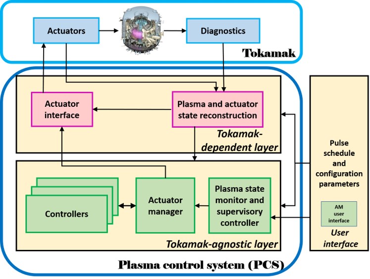
The main function of each component in the tokamak-agnostic layer is summarized as follow:
-
•
a plasma and actuator event monitor [5] categorizes the state representation of the plasma, the events and the actuators
-
•
a supervisor evaluates the occurrence of ONEs and decides the appropriate control scenario (list of control tasks), then activates and prioritizes relevant tasks
-
•
an actuator manager defines the best actuator resource allocation to active tasks by solving an optimization problem based on the available actuator resources and the resource requests from controllers; and later distributes commands to corresponding actuators
-
•
controllers execute control laws to fulfill their tasks with assigned resources and also ask for new actuator resources for the next time step
The modular and interface-standardized features of the tokamak-agnostic layer allow us to reduce implementation errors, as well as improve maintenance and development capabilities. For more details about the tokamak-agnostic layer and the interfaces of each component in this layer, the reader can refer to our previous work [1] and the references therein.
III Supervisor decision
We will focus on a strategy of supervisor decision to deal with ONEs (e.g. magneto-hydrodynamic instabilities such as Neoclassical Tearing Mode (NTM), locked mode; or the events when the plasma/actuator states approach the physical/technical limits, such as density limit, actuator amplitude limit, actuator energy limit, etc.) which can lead to plasma disruption or plasma performance deterioration. Here the centralized supervisor plays the main role to decide the action for ONE handling. Associated with the centralized actuator resource allocator, this supervisory level can ensure a non-conflicting and flexible use of available actuators. A series of control scenarios are prepared in the pulse schedule corresponding to various actions to be selected in real-time by the supervisor.
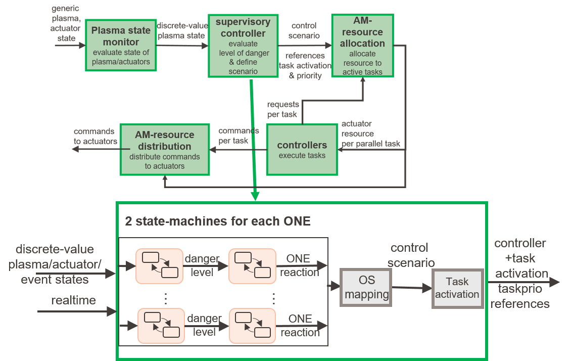
Fig. 2 presents the relevant modules of the tokamak-agnostic layer, as well as a zoom of the supervisor which determines the control scenario output, based on the discrete-value plasma state and actuator state inputs. For each ONE, first the danger level and the ONE-reaction level are determined. Then a ONE to Scenario (OS) mapping is used to decide the appropriate control scenario based on a given set of ONEs and the associated ONE-reaction levels.
Two finite-state-machines are used to classify the danger level and reaction level of each ONE (Fig. 2). It is important to notice that the thresholds for the transitions from one state to another in the finite-state-machines are customized in the user interface as tunable parameters, which can be modified from shot to shot. Two lists of states of these finite-state-machines are also shown in TABLE I.
a. ![[Uncaptioned image]](/html/2010.16145/assets/x1.jpg) b.
b.
![[Uncaptioned image]](/html/2010.16145/assets/x2.jpg)
The number of danger levels and reaction levels are independent and only coincidental the same here.
III-A Danger level
Five (states) levels of danger are defined in TABLE I.a. The classification of a ONE danger level is based either on one generic state (amplitude state, position state, etc) or on the combination of various generic states from the plasma event monitor. On the other hand, in order to avoid ambiguity while several ONEs simultaneously appear and their combination can significantly change the situation, a virtual ONE using their combination should be created as a new independent event. For example, a locked mode in low danger level will really become significant if there is also an observed increase in radiated power. In this case, a combined event must be considered separately from the lock mode and the radiated power events.
III-B Off-normal-event (ONE)-reaction level
The danger level is then used to define the ONE-reaction-level whose states are listed in TABLE I.b and are enumerated from to , corresponding to the five basic types of control scenarios that we consider at this stage (see III-C). Examples of finite-state-machines for ONE reaction are shown in Fig. 3.a and 4.a. It’s worth noting that some states are irreversible, for instance, state level and . These states correspond to irreversible actions such as soft-shutdown or mitigation. It is also important to note that the mapping between the danger levels and the ONE-reaction levels is specific for each ONE, thus they are not always 1-1 corresponding (see e.g. Fig. 3.a, the difference between and events).
III-C ONE reaction to scenario (OS) mapping
To select the control scenario to be executed in the current time-step, an OS mapping (Fig. 3.b) based on the combination of the ONE-reaction levels of all active ONEs is thus necessary. A finite number of control scenarios are derived from the given pulse-schedule. We define five basic types of control scenarios: normal, recovery, backup, soft-shutdown, and disruption-mitigation. Several control scenarios of the same type can be defined. For example, we often have one normal, which is the desired/original/basic scenario, one soft-shutdown, and one disruption-mitigation, but several recovery and several backup scenarios depending on the considered ONEs and the control actions on them. For instance, with two considered ONEs, if only the first ONE needs a recovery control action (ONE-reaction level ), recovery_1 scenario is selected; if only the second ONEs gets ONE-reaction level , recovery_2 scenario is chosen instead; otherwise if both of them need to be recovered, recovery_3 scenario is selected this time. Finally, a list of control tasks is determined by the user for each control scenario in order to achieve the desired control action, as shown in the example in TABLE II.
Once the appropriate control scenario is selected based on the actual plasma situation, the relevant control tasks will be activated, and the corresponding references are taken into account according to the user setting for each control scenario before the discharge. The actuator manager and the controllers perform their normal functionality without any judgment on the ONEs.
III-D Example
In this subsection, two NTM events: and are considered to be simultaneously detected. Their danger states are determined based on the discrete-value states of their amplitudes from the plasma event monitor. Due to the different danger potential of the considered events, their state-machines for the ONE reaction level are not the same. For instance, the is not very dangerous, it only leads to a reduction of neutron productions, thus the reaction is either no-action () or recovery (). On the other hand, the requires all actions up to mitigation (), since a mode can trigger disruptions. Depending on the reaction level associated with these ONEs as well as the pre-defined OS mapping, the control scenarios are different for the two situations as shown in Fig. 3 and 4: backup1 and mitigation respectively.
In TABLE II, some relevant tasks are listed associated with each control scenario in this example. A control scenario will be chosen by the supervisor for each instant, thus the considered tasks in this scenario will be activated based on the task activation conditions (time intervals, event triggers, etc.). Regarding the first situation where the backup1 scenario is selected, three tasks stabilization, control and heating feedforward can be simultaneously activated. The actuator manager determines the best actuator resource allocation per task based on the actuator states as well as the requests for actuator resources per task from the controllers. Three corresponding controllers: NTM controller, performance controller and feedforward controller are used to carry out the three considered tasks, respectively. The controllers execute their control laws and do their best to fulfill their given tasks with the assigned resources. Here, the NTM controller commands to move the EC beam deposition to the target ( position), and uses all EC power that it receives at the target. The performance controller in this case is a PID controller which asks to modify the heating power according to the gap between the RT estimated (corresponding to the total thermal energy) and its reference. The feedforward controller reproduces a heating power command which is configured by the user before the discharge. All the commands from the controllers are combined and then sent to the tokamak-dependent layer, where they are converted into the specific actuator commands, e.g. heating power into voltage, radial deposition location of EC power into launcher angles, etc.
a. 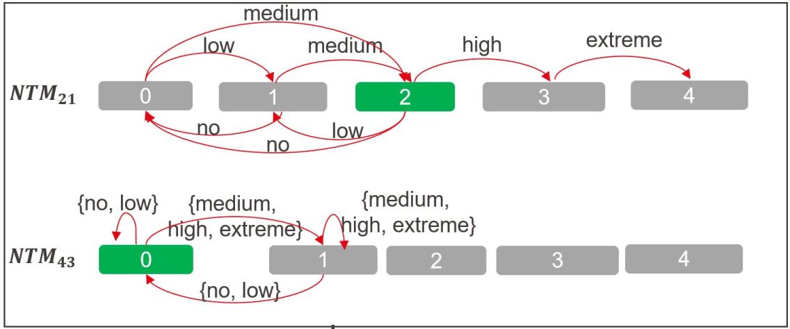
b. 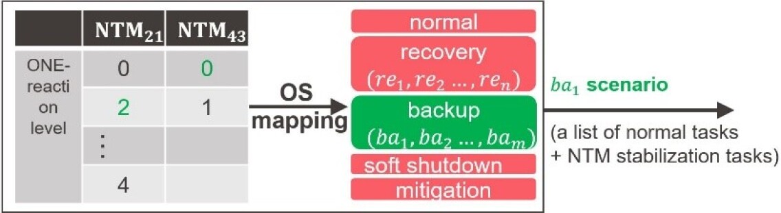
a. 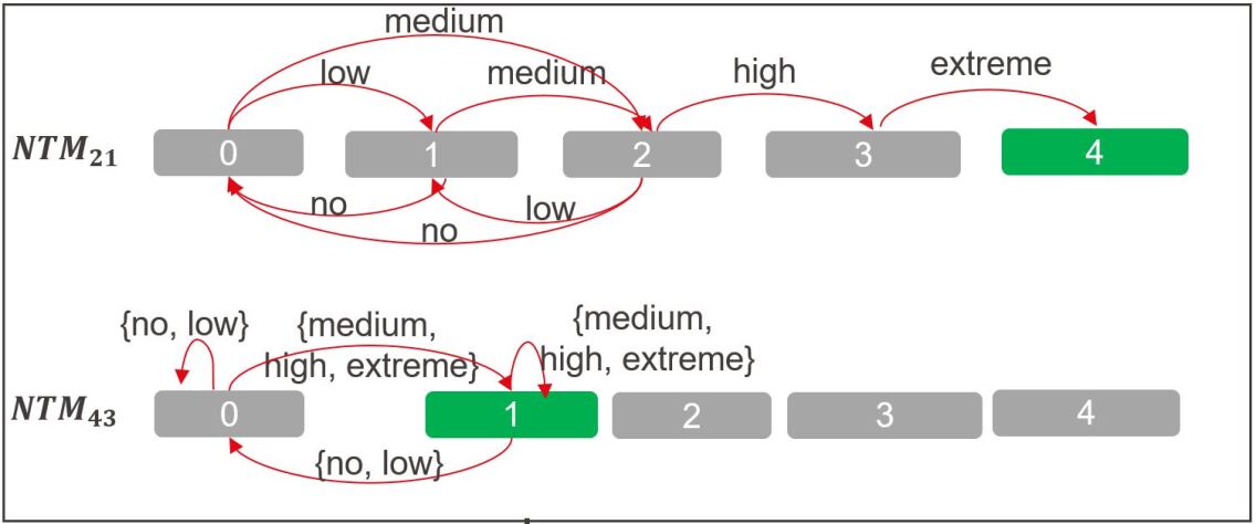
b. 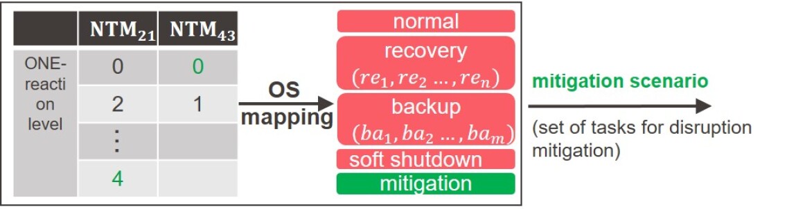
![[Uncaptioned image]](/html/2010.16145/assets/x7.jpg)
Note that reference, feedforward reference, etc. are tunable parameters which are given from the user interface
IV Experimental result
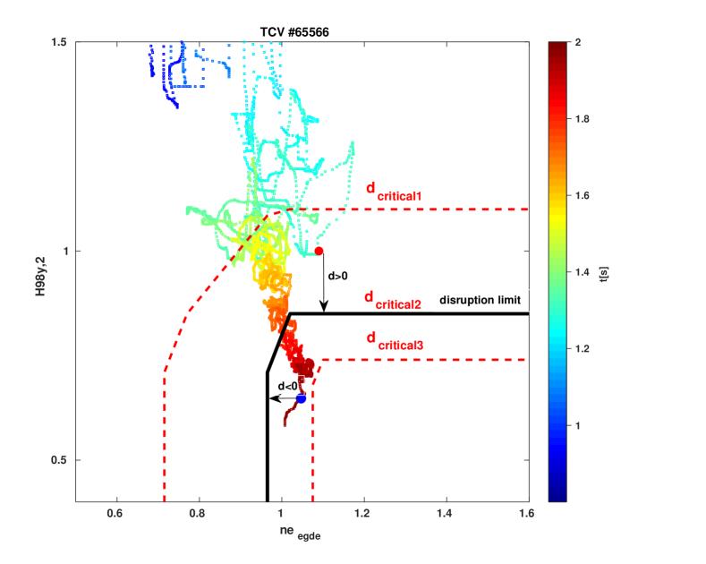
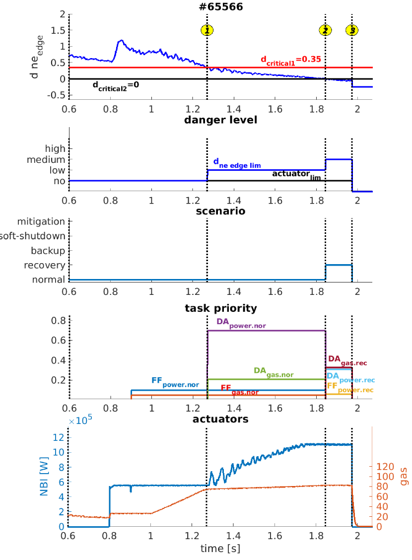
The proposed PCS has been implemented in MATLAB/ Simulink, from which C code was generated and included in the TCV digital real-time control system (cf. [11, 12]). An application for disruption avoidance experiments is presented in Fig. 6, where the discharge is pushed towards the H-mode density limit disruption by a gas-flux ramp. The main purpose of disruption avoidance experiments is to avoid the abrupt loss of energy confinement, or even to recover the plasma to the previous stable states. However, in this experiment, we aim to control the plasma to slowly approach the density limit for detailed physics studies. Several new modules have been implemented in the TCV PCS to determine in RT: the factor characterizing the energy confinement time, and the normalized edge density [13]; together, we derive the distance between the system states and the empirical disruption limit (see Fig. 5). This distance is the key factor used by the supervisory layer to determine an appropriate control scenario. In this example, two ONEs are considered: and for the NBI energy limit. The supervisor evaluates the dangers from these ONEs to switch between different scenarios: normal, recovery, and soft-shutdown, in which three sets of relevant control tasks are configured beforehand.
In Fig. 6, second panel, the danger level of the is low from \small1⃝ when the distance is below the first critical threshold , and is medium from \small2⃝ when the distance is below the second threshold ; while the danger is high when the NBI energy reaches the threshold of the total energy of (which is not the case in this experiment) and is no otherwise. Here, the customized ONE reaction levels based on the danger level of each ONE are specified in TABLE III.
![[Uncaptioned image]](/html/2010.16145/assets/Figures/danger_reaction_mapping.png)
The control scenario (third panel) is based on the combination of the reaction levels of the two ONEs, which is recovery if the highest danger level reaches medium from \small2⃝, otherwise it remains normal. According to the chosen scenario, different control tasks are activated and prioritized (fourth panel). In normal scenario, the feedforward task asks for a constant heating power of and the commands a fast gas-flux ramp. The disruption-avoidance task modifies the power according to the distance only when it is below the , and the reduces the gas-flux ramp. In recovery scenario, the is the same as the , while the asks for the maximum power and the keeps the gas flux constant. Consequently, on the one hand, the NBI power (last panel) is composed of a constant power () and an extra power () increasing proportionally up to the maximum heating power . On the other hand, the gas flux is first increasing fast (), then slowly () at \small1⃝, and finally is frozen () at \small2⃝. This allows a slow and well-controlled approach to the density limit for detailed physics studies. A soft-shutdown scenario is also set up with two feedforward tasks to cut off both the NBI power and the gas flux in a controlled manner when the distance goes below the . Unfortunately, in that case, the discharge disrupted before that situation happens.
V Conclusion
This work presents a supervisory strategy to deal with off-normal-events. Each ONE is evaluated for its danger level and the necessary reaction, then a global decision is made to define an appropriate control scenario. The presented control architecture has been successfully implemented and tested on the TCV tokamak in the context of density limit disruption avoidance experiments; employing the exposed control scenario switching methodology. It has been fruitfully capable of smoothly reaching density limits in various plasma discharges. This architecture will be used for different integrated control objectives such as simultaneous controls of L-H mode, NTM, , and profile, etc. in the upcoming experiments.
Acknowledgment
This work was supported in part by the Swiss National Science Foundation. This work has been carried out within the framework of the EUROfusion Consortium and has received funding from the Euratom research and training programme 2014 - 2018 and 2019 - 2020 under grant agreement No 633053. The views and opinions expressed herein do not necessarily reflect those of the European Commission.
References
- [1] N.M.T Vu et al. Fusion Eng. Des., 147 111260, 2019.
- [2] R. Nouailletas et al. Fus. Sci. & Tech., 64(1): 13-28, 2013.
- [3] N.W. Eidietis et al. Nucl. Fusion, 58 056023, 2018.
- [4] M. Maraschek et al. Plasma Phys. Control Fusion, 60 1, 2018.
- [5] T. Blanken et al. Nucl. Fusion 59, 59(2) 026017, 2019.
- [6] F. Carpanese et al. Nucl. Fusion, 60 066020, 2020.
- [7] E. Poli et al. Comput. Phys. Commun., 225 36, 2018.
- [8] M. Weiland et al. Nucl. Fusion, 58 082032, 2018.
- [9] O. Kudlacek et al. Fusion Eng. Des., 159 111735, 2020.
- [10] E. Maljaars and F. Felici. Fusion Eng. Des., 122:94–112, 2017.
- [11] C. Galperti et al. Trans. on Nucl. Science, 64(6), 2017.
- [12] F. Felici et al. Fusion Eng. Des., 89:155–164, 2014.
- [13] M. Bernert et al. Plasma Phys. Control Fusion, 57 014038, 2015.