Ray-marching Thurston geometries
Abstract.
We describe algorithms that produce accurate real-time interactive in-space views of the eight Thurston geometries using ray-marching. We give a theoretical framework for our algorithms, independent of the geometry involved. In addition to scenes within a geometry , we also consider scenes within quotient manifolds and orbifolds . We adapt the Phong lighting model to non-euclidean geometries. The most difficult part of this is the calculation of light intensity, which relates to the area density of geodesic spheres. We also give extensive practical details for each geometry.
1. Introduction
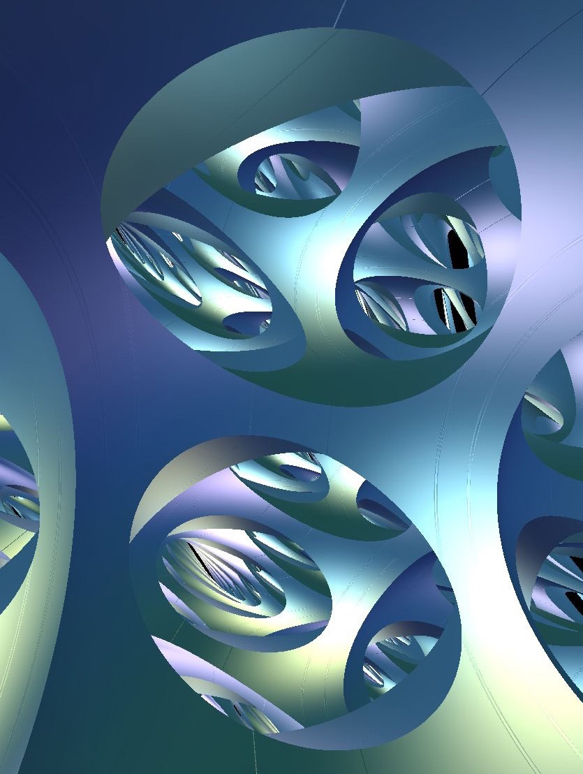
In this paper we describe a project we initiated at the Illustrating Mathematics semester program at ICERM in Fall 2019. The goal of this project is to implement real-time simulations of the eight Thurston geometries in the in-space view – that is, viewed from the perspective of an observer inside of each space, where light rays travel along geodesics. See Figure 1.1. We have collected many of our simulations and videos of them at the website http://www.3-dimensional.space.
These simulations may be experienced with an ordinary keyboard and screen interface, and in some cases in virtual reality. We expect that these simulations will be useful in outreach, teaching, and research. Seeing and moving within a space gives a visceral experience of the geometry, often engendering understanding that is hard or impossible to obtain from “book learning” alone. Recent research on embodied understanding [LTWJ16, JGMR17, GPE17] addresses these advantages.
The code for our simulations is available online [CMST20c]. We hope that other researchers will be able to use and extend our work to visualize objects of interest in the Thurston geometries and beyond. In two previous expository papers, we described some surprising features of the Nil [CMST20a] and Sol [CMST20b] geometries using images from our simulations.
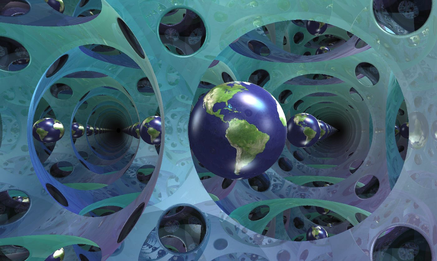
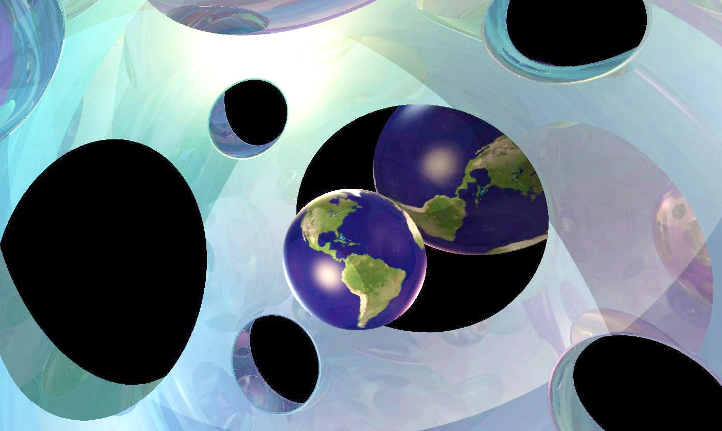
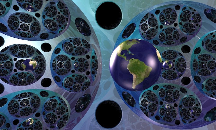
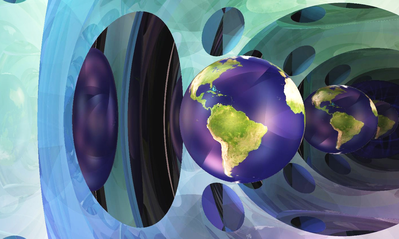
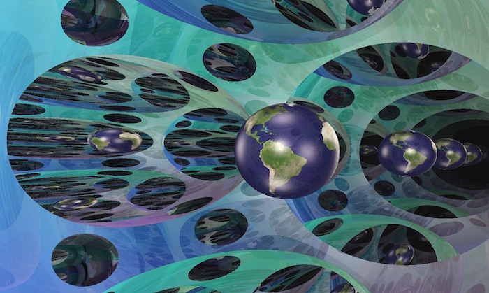
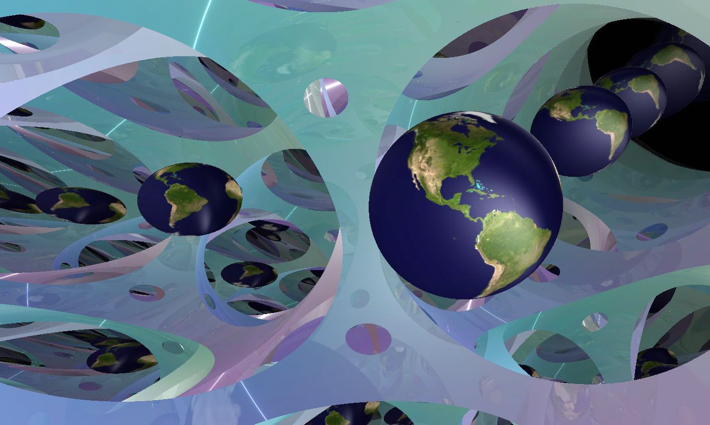
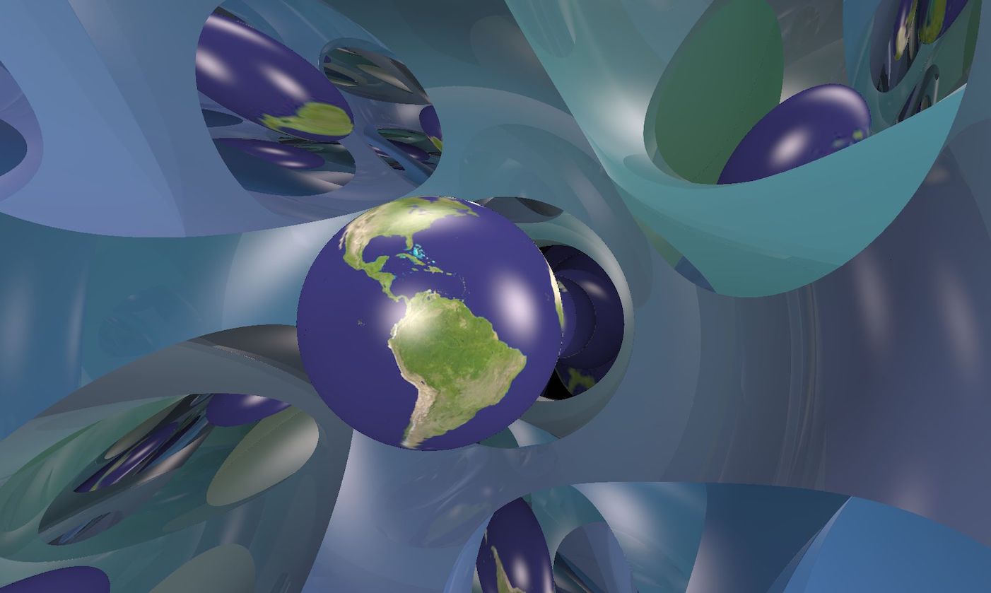
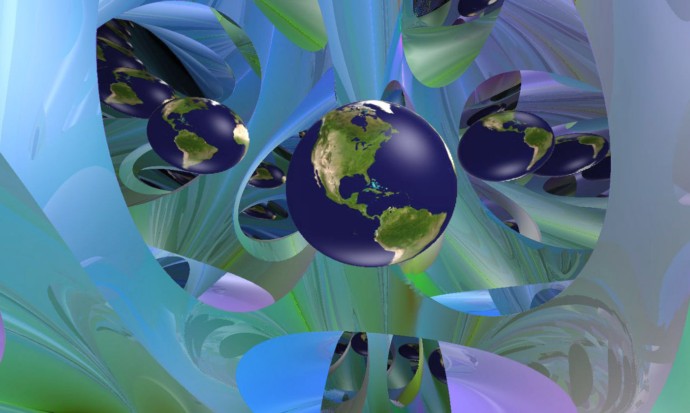
1.1. Thurston’s eight geometries
The expansion of geometry beyond euclidean -space traces its origins to the century discovery of hyperbolic geometry. From here, Klein made the following wide-reaching generalization. A homogeneous geometry is a pair consisting of a smooth manifold , equipped with the transitive action of a Lie group . The manifold defines the underlying space of the geometry, and the group defines the collection of allowable motions. This convenient mathematical formalism turns some of our traditional geometric thinking upside down. Instead of defining euclidean geometry as with a particular metric, we define it as with a particular group of allowable diffeomorphisms (rotations, reflections, and translations), and derive as a consequence the existence of an invariant metric.
In dimension two, homogeneous geometries play an outsized role in mathematics, in large part due to the uniformization theorem. This implies that every two-dimensional manifold can actually be equipped with a geometric structure modeled on one of the homogeneous spaces or . Because of this, one may often use geometric tools in settings without an obviously geometric nature. In the 1970s and 1980s, Thurston came to realize that a similar (but more complicated) result might hold in three dimensions. Thurston’s geometrization conjecture stated that every closed three-manifold may be cut into finitely many pieces, each can be built from some homogeneous geometry. The proof of geometrization was completed by Perelman in 2003 [Per02, Per03a, Per03b] and provides a powerful tool in three-dimensional topology. This also resolved the Poincaré conjecture, which had been open for more than a century. The eight geometries required for geometrization can be defined abstractly as follows. A homogeneous space is a Thurston geometry if it has the following four properties:
-
(1)
is connected and simply connected.
-
(2)
acts transitively on with compact point stabilizers.
-
(3)
is not contained in any larger group of diffeomorphisms acting with compact stabilizers.
-
(4)
There is at least one compact manifold.
The first of these conditions rules out unnecessary duplicity in our classification. Every connected geometry is covered by a simply connected universal covering geometry, so it suffices to consider these. The second condition is the group-theoretic way of requiring that has a -invariant riemannian metric, and the third condition is just the statement that is actually the full isometry group. A geometry satisfying (1)–(3) is called maximal. The fourth condition recalls our original motivation: to study geometric structures on compact manifolds in dimension three; we need only concern ourselves with geometries which can be used to build geometric structures!
Three dimensions is small enough that all of the Thurston geometries arise from relatively simple constructions111There are 19 maximal geometries in dimension four [Hil02], and 58 in dimension five [Gen16]. While many of these can be constructed by analogous procedures, some new phenomena also arise., growing out of either two-dimensional geometry or three dimensional Lie theory. This divides the set of Thurston geometries into a collection of overlapping families of geometries constructed by similar means. Some of these families are listed below and illustrated in Figure 1.2.
2pt \pinlabel at 520 760 \pinlabel at 940 760 \pinlabel at 150 610 \pinlabel at 660 510 \pinlabelNil at 1060 510 \pinlabel at 370 330 \pinlabel at 805 230 \pinlabelSol at 1140 200
Isotropic [l] at 1710 742
\pinlabelProduct [l] at 1710 596
\pinlabelIsometry group [l] at 1710 449
\pinlabelBundle [l] at 1710 302
\pinlabel3D Lie group [l] at 1710 156
\endlabellist
-
(1)
Isotropic Geometries. A geometry is isotropic if the point stabilizer contains . This acts transitively on the unit tangent sphere at a point. Since directions and planes are dual to each other, any -invariant metric on must have constant sectional curvature. Thus, this family consists of and .
-
(2)
Products of Lower Dimensional Geometries. The product of the unique one-dimensional geometry (denoted in this paper) and any two-dimensional geometry gives a geometry of dimension three. This family consists of the three geometries and . The latter is not maximal: its isometry group is contained in that of .
-
(3)
Isometry groups of two-dimensional geometries. Each of the two-dimensional geometries is isotropic, so acts transitively on the unit tangent bundle . Thus we may consider the three-dimensional geometry , and get a maximal geometry by taking covers and extending the isometry group if necessary. This gives the geometries and , as well as the new geometry (built from , and respectively).
-
(4)
Bundles over two-dimensional geometries. Generalizing both of the previous cases, we may construct all geometries where has a -invariant bundle structure over a two-dimensional geometry. This produces one new example: Nil, a line bundle over . This bundle structure has an important geometric consequence: all manifolds with these geometries are Seifert fibered.
-
(5)
Three-dimensional Lie groups. Every three-dimensional Lie group acts on itself freely by left translation. Starting from the homogeneous geometry , we may build a maximal geometry by taking covers and extending the group of isometries, if necessary. Assuming that is unimodular, this construction recovers the unit tangent bundle geometries and Nil, and produces our final geometry, [Mil76, Section 4]. Allowing Lie groups that are not unimodular, we also recover and .
1.2. Goals
We have the following goals for the algorithms we use to render our in-space views.
-
(1)
Our images must be accurate – assuming that light rays travel along geodesics, there is a correct picture of what an observer inside of a given geometry would see. Our images should accurately portray this picture.
-
(2)
Real-time graphics algorithms must be very efficient in order to run at an acceptable frame rate. This is particularly important in virtual reality – around 90 frames per second is recommended to reduce nausea. Modern graphics cards allow for the required speed, given efficient algorithms.
-
(3)
Our algorithms must allow for a full six degrees of freedom in the position and orientation of the camera, even when the simulated geometry may not have a natural corresponding isometry. A user in a virtual reality headset can make such motions, and the view they see must react in a sensible way.
-
(4)
As much as is possible, our algorithm should be independent of the geometry being simulated. The idea here is that it should be possible to change the code in a small number of places to convert between simulations of different geometries. Compartmentalizing the code in this way will make it easier to extend it to further geometries, beyond Thurston’s eight.
-
(5)
When possible, we should make our images beautiful, allowing for graphical effects including lighting, (hard and soft) shadows, reflections, fog, etc.
Some of these goals are of course in conflict. Adding features such as shadows and reflections increases the amount of work needed to be done per frame, which can reduce the frame rate. The frame rate is also dependent on the desired screen resolution. There are many trade-offs to be made between fidelity and speed.
We use the relatively new technique of ray-marching in our implementation. We discuss this technique and compare it with other graphics techniques in Section 2. One key feature is that the data and calculations needed to generate images for each geometry are relatively simple in comparison to other techniques, which makes it easier to write geometry independent code.
1.3. Related work
This project owes its existence to a long history of previous work. It is a direct descendant of the hyperbolic ray-marching program created by Nelson, Segerman, and Woodard [NSW18], which itself was inspired by previous work in and by Hart, Hawksley, Matsumoto, and Segerman [HHMS17a, HHMS17b], all of which aim to expand upon Weeks’ Curved Spaces [Wee] which in turn is a descendant of work by Gunn, Levy and Phillips [PG92, MLP+14] and others at the Geometry Center in the 1990’s. Thurston was a driving force for much of this visualization work. He often spoke about what it would be like to be inside of a three-manifold [Thu98]. The software SnapPy [CDGW] was originally developed by Weeks to calculate the geometry on hyperbolic three-manifolds using Thurston’s hyperbolic ideal triangulations. Concurrent with this project’s development at ICERM in Fall 2019, Matthias Goerner implemented an inside view for hyperbolic manifolds within SnapPy, using a ray-tracing strategy.
Perhaps the earliest work concerned with rendering the inside-view of non-euclidean geometries is due to theoretical physicists predicting the appearance of black holes; this field goes back to the 1970’s [Lum19].
The past few years have seen a number of independent projects building real-time simulations of inside views for the Thurston geometries, including the last three “harder” geometries. To our knowledge, Berger [Ber15, BLV15] produced the first in-space images of all eight Thurston geometries. He uses ray-tracing, with a fourth-order Runge–Kutta method for numerical integration to approximate geodesic rays.
The HyperRogue project [KCv17], by Kopczyński and Celińska-Kopczyńska implements all eight geometries with a triangle rasterization based strategy. They restrict the parts of the world that the viewer can see in order to avoid some issues with this approach that we identify in Section 2.3.1. For example, in certain geometries one can only see a limited distance in particular directions. They also use a fourth-order Runge–Kutta method to approximate geodesic rays, and rely in part on lookup tables for speed. Their motivation is more towards implementation for use in computer games. Here it is very useful to be able to use polygon meshes to represent the player character, enemies, and other objects in the game world. Kopczyński and Celińska-Kopczyńska [KCK20] also provide a real-time ray-tracing implementation of Nil, and Sol.
Novello, Da Silva, and Velho [VdSN20, NdSV20c] share our interest in implementing virtual reality experiences. They also implement in-space views with a ray-tracing approach, tackling all of the Thurston geometries other than the product geometries. They use Euler’s method for numerical integration to approximate geodesic rays for and Sol.
Other than ours, the only ray-marching approach we are aware of is due to MagmaMcFry [Mag19], who implements , Nil, , and Sol. They use a second-order Runge–Kutta method to approximate geodesic rays.
A numerical integration approach is unavoidable in some cases, for example in generic inhomogeneous geometries [NdSV20a]. These approaches can also minimize the differences in the code for different geometries. However, such algorithms must take many steps along each ray to maintain accuracy, and so may be slow. This may be acceptable when the scene is “dense” – implying that few rays travel very far before hitting an object. This often happens for example, with a co-compact lattice. For scenes in which rays travel large distances we lose accuracy unless the number of steps is large, meaning that we lose rendering speed.
We instead use explicit solutions for our geodesic rays in almost all cases. This moves the problem of accuracy versus speed to the implementation of the functions involved in the solutions. In this setting however, we have reduced the problem of understanding the long-term behavior of the geodesic flow to studying the long-term behavior of these component functions. It turns out that these functions are well-understood for the eight Thurston geometries (they are trigonometric, hyperbolic trigonometric, and Jacobi elliptic functions). Thus we can often take large steps along geodesics and achieve both accuracy and speed, even for objects that are distant from the viewer. We exploit this ability to illustrate counterintuitive, long-range behavior of geodesics in Nil and Sol [CMST20a, CMST20b]. In Appendix A we give the results of some numerical experiments comparing the performance and accuracy of Euler and Runge–Kutta numerical integration with explicit solutions in Nil and .
Acknowledgements
This material is based in part upon work supported by the National Science Foundation under Grant No. DMS-1439786 and the Alfred P. Sloan Foundation award G-2019-11406 while the authors were in residence at the Institute for Computational and Experimental Research in Mathematics in Providence, RI, during the Illustrating Mathematics program. The first author acknowledges support from the Centre Henri Lebesgue ANR-11-LABX-0020-01 and the Agence Nationale de la Recherche under Grant Dagger ANR-16-CE40-0006-01. The second author was supported in part by National Science Foundation grant DMR-1847172 and a Cottrell Scholars Award from the Research Corporation for Science Advancement. The third author was supported in part by National Science Foundation grant DMS-1708239.
We thank Joey Chahine for telling us about a computable means of finding area density. We thank Arnaud Chéritat, Matei Coiculescu, Jason Manning, Saul Schleimer, and Rich Schwartz for enlightening discussions about the Thurston geometries at ICERM.
2. Ray-marching
Ray-marching is a relatively new technique to produce real-time graphics using modern GPUs [Won], although its roots go back to the 1980’s at least [HSK89]. Ray-marching is similar to ray-tracing in that for each pixel of the screen, we shoot a ray from a virtual camera to determine what color the pixel should be. Unlike most ray-tracing implementations however, the objects in the world that our ray can hit are not described using polygons. Instead, we use signed distance functions, which we describe in the following.
Definition 2.1.
Let be the ambient space, and suppose that is a closed subset of . We refer to as a scene. We define the signed distance function for as follows. For a point , the function returns the radius of the largest ball centered at whose interior is disjoint from . For the function is non-positive, and is the radius of the largest ball centered at contained in . ∎
We will sometimes write for . We often refer to a part of a scene as an object. As an example, suppose that is euclidean three-space, , and our scene is a ball of radius , centered at the origin. Then the signed distance function is
| (2.2) |
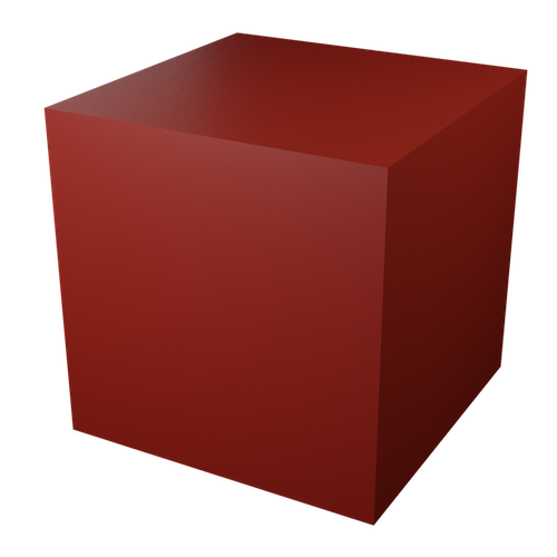
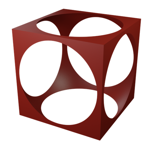
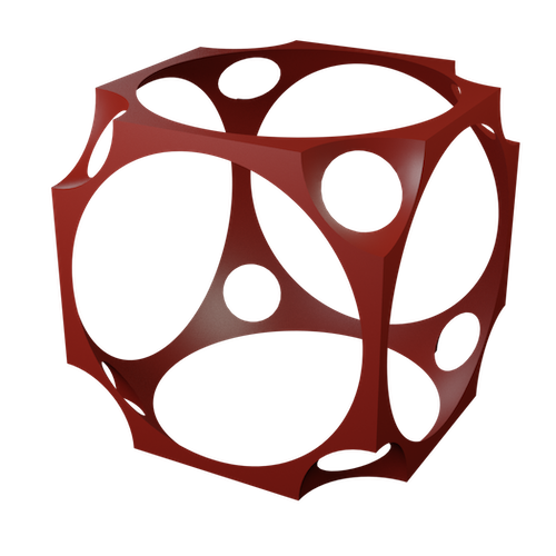
Suppose that we have multiple scenes, described by signed distance functions . Then the signed distance function for the union of the scenes is . The complement of a scene is given by the negative of its signed distance function. We often draw a tiling in an inexpensive manner by deleting a ball from the center of each tile. See Figure 2.1 and Remark 4.4. For more examples of signed distance functions in , and more ways to combine signed distance functions, see [Quia].
To render an image of our scene, we place a virtual camera in the space at a point . We identify each pixel of the computer screen with a tangent vector at , and so determine a geodesic ray for this pixel, starting at . To color the pixel, we must work out what part of the scene the ray hits. The algorithm is illustrated in Figure 2.2. We start at , the position of the camera, as shown in Figure 2.2a. We assume that is not inside the scene. We evaluate the signed distance function at . Since no part of the scene is within of , we can safely march along our ray by a distance of without hitting the scene. We call the resulting point . We can then safely march forward again by to reach . We repeat this procedure until either we reach a maximum number of iterations, or we reach a maximum distance, or the signed distance function evaluates to a sufficiently small threshold value, say. In the first two cases we color the pixel by some background color. In the third case (as shown in Figure 2.2d) we declare that we have hit the scene.
In the case that we hit the scene, we may then choose a color for the pixel based on which part of the scene we hit, apply a texture, and/or apply various lighting techniques, for example the Phong reflection model [Pho75]. Note that this model requires the normal vector to the surface at the point our ray hits; this is easily approximated using the gradient of the signed distance function.
2pt
\pinlabel [bl] at 160 210
\endlabellist
2pt
\pinlabel [bl] at 160 210
\pinlabel [b] at 237 160
\endlabellist
2pt
\pinlabel [bl] at 160 210
\pinlabel [b] at 237 160
\pinlabel [b] at 290 120
\endlabellist
2pt
\pinlabel [bl] at 160 210
\pinlabel [b] at 237 160
\pinlabel [b] at 290 120
\endlabellist
2.1. Geometric convergence
A concern one might have over the ray-marching algorithm is the potentially large number of steps taken before we are close enough to the scene to declare that we have hit it. Indeed, functions called in the innermost loop of the algorithm must be made as efficient as possible. However, the number of steps used is generally not prohibitive. Suppose that our scene has a smooth boundary. In this case, when we are close enough to its boundary may be approximated by a plane . If our ray continues to approach , then we converge to it as a geometric series, see Figure 2.3. The base of the exponent depends on the angle of incidence of the ray, approaching the worst case of as the ray becomes tangent to .
2pt
\pinlabel [b] at 140 15
\pinlabel [b] at 251 15
\pinlabel [b] at 295 15
\pinlabel [b] at 330 15
\endlabellist
Remark 2.3.
If the maximum number of steps we allow before giving up is too small, then we may erroneously color pixels with the background color whose rays would eventually hit an object. This will often be most visible around the outer edges of an object in the scene, as these rays are the closest to tangent. These rays spend many steps moving a small distance close the object. Thus, they may run out of iterations before converging. ∎
2.2. Distance underestimators
The signed distance function for a scene may be difficult or expensive to calculate. In these cases we may wish to replace it with an easier to calculate approximation.
Definition 2.4.
Suppose that is the signed distance function for a scene . We say that a function is a distance underestimator if
-
(1)
The signs of and are the same for all points ,
-
(2)
for all , and
-
(3)
If is a sequence of points in such that , then . ∎
We do not require that is continuous, but the second and third conditions here imply that a distance underestimator vanishes only on the boundary of .
Lemma 2.5.
When ray-marching with a distance underestimator in place of a signed distance function , we limit to the same point as when using .
This result implies that a distance underestimator will give us essentially the same images as the signed distance function, given enough iterations and a small enough threshold . If a distance underestimator is significantly easier to compute than the signed distance function then trading an increased number of iterations for improved speed of computation can be advantageous. See Sections 9.6 and 10.6 for examples of distance underestimators.
Proof of Lemma 2.5.
Consider a ray starting at a point . Suppose that first meets the scene at the point . Using the distance underestimator , we march through a sequence of points Consider the distances , measured along the ray from to . By conditions (1) and (2), we know that the sequence is a non-negative non-increasing sequence. Thus converges, and so the sequence of points , converges. Thus the distances must go to zero. These are the distances we march along the ray, using the distance underestimator , so . Therefore . By condition (3), , and so . ∎
In practice we want and to be “coarsely the same”. In particular, to get condition (3), we want to be bounded below by some function of . This also allows us to control how many extra iterations are needed in ray-marching with a distance underestimator.
Any real-world implementation cannot go all the way to the limit point and instead stops at some sufficiently small value, . Thus, a distance underestimator should not return a value smaller than unless the signed distance function is also small.
2.3. Advantages of ray-marching in non-euclidean geometries
Ray-marching is an attractive technique in euclidean geometry, in part because of the simplicity of its implementation. This is also true for non-euclidean geometries. Here we discuss some alternative techniques.
2.3.1. Z-buffer triangle rasterization
Real-time graphics in euclidean geometry are usually rendered using z-buffer triangle rasterization. In this technique, objects in the scene are represented by polygon meshes. A projection matrix maps each triangle of a mesh onto the plane of the virtual camera’s screen. For each pixel , we look at the triangles whose projections contain the center of . Of these triangles, the one closest to the camera determines the color of .
This works well for the isotropic Thurston geometries, and , in particular because geodesics in these geometries are straight lines in their projective models, see [Wee02]. Jeff Weeks uses these in his Curved Spaces software [Wee]. There is one complication with here, in that a single object is visible in two different directions: the two directions along the great circle containing the camera and the object. This means that each object must be projected twice. This is acceptable for . In Nil, Sol, and , a single object can be visible from the camera in many directions, with no uniform bound on the number of such directions. Even worse, in a single object can be visible in infinitely many directions from a single camera position.
The projection matrix used in triangle rasterization implements the inverse of the exponential map. In the cases listed above, the exponential map is not one-to-one. This is not a problem for ray-tracing and ray-marching, which both use the forward direction of the exponential map instead.
2.3.2. Ray-tracing
Ray-tracing is very similar to ray-marching, with the difference being in how we determine where in the scene a ray hits. In many applications the objects in the scene are described by polygon meshes, as in triangle rasterization. The algorithm checks for intersection between the ray and the polygons of the mesh. To make this efficient for (euclidean) scenes with a large number of polygons, much effort is put into checking as few triangles for collision as possible, even though each individual check is inexpensive. However, objects described by simple equations such as spheres and other conics can also be used: all that is needed is a way to check whether or not a ray intersects the object, and at what distance along the ray. The distance is used to decide which object is closest to the camera and so should be drawn. For a conic in euclidean space for example, this check and distance may be calculated by solving a quadratic equation.
One advantage of ray-tracing over ray-marching is that ray-tracing is well suited to rendering objects given by polygon meshes. It therefore has access to decades of development in polygon modeling techniques and rendering efficiency for polygonal models. On the other hand, depending on the geometry, checking for intersection between a ray and an object may be difficult. In place of this check in ray-tracing, for ray-marching we only need a signed distance function (or distance underestimator). If for example we make our scene from balls, then we only need to calculate distances between points.
2.4. Accuracy
One of our goals in this project is to be able to render features accurately, even at long distances. We identify two potential sources of error here.
2.4.1. Floating point representation of number
First, the representation of real numbers by floating point numbers is necessarily inaccurate. This can be a problem in a number of ways, whether one is ray-marching, ray-tracing, or using polygon rasterizing methods.
-
(1)
In certain models, the coordinates of points grow exponentially with distance in the geometry, and floating point numbers quickly lose precision. In particular, this causes problems when rendering objects that are far from the camera. Of the eight Thurston geometries, this is an issue in , Sol, and . This can be mitigated by the choice of model [FWW02]. Even without exponential growth in coordinates, floating point numbers cannot exactly represent geometric data.
-
(2)
In certain regimes, a formula may be unstable. For example, the formula approaches as approaches zero. However, the available precision in the floating point representation of near is not very good in comparison to the precision of . In such a regime, it is better to use a different representation of the formula. Here for example, we will get much better results by using an asymptotic expansion, say .
2.4.2. Accumulation of errors
Any iterative algorithm that takes the result from the previous step as the input for the next step may accumulate errors. These errors may come from lack of precision due to floating point representations as described above. They may also come from limitations in the methods used to calculate geodesic flow. As mentioned at the end of Section 1.3, to remove this second source of error we avoid the numerical integration approach whenever possible, preferring explicit solutions.
3. General implementation details
As mentioned in Section 1.2, one of our goals in this project is to make as much of our code as possible independent of the geometry being simulated. Following this goal, in the next few sections we describe components needed for our simulations that are shared across geometries. Many of these apply to all eight Thurston geometries. However, it is also useful to discuss strategies for tackling smaller collections of geometries with certain geometric or group theoretic features. Thus to begin, we provide a second grouping of the Thurston geometries into overlapping families, distinct from our first grouping by method of construction in Section 1.1.
Consider the following properties:
-
(1)
The geodesic flow is achieved by isometries. That is, every geodesic is the orbit of a point under a one-parameter subgroup.
-
(2)
The projective model has straight-line geodesics. Each of the Thurston geometries (up to covers) has a model with and . With this property, the geodesics of are projective lines in this model.
-
(3)
The group has a normal subgroup whose action is free and transitive on .
Property (1) implies that parallel transport is achievable directly via elements of . Property (2) implies that totally geodesic surfaces are planes in the projective model, which makes testing membership in polyhedral domains (for example, Dirichlet domains) efficient. Property (3) allows us to canonically identify tangent spaces at distinct points of . This allows us to reduce certain difficult calculations (for example, the geodesic flow) to differential equations in a fixed tangent space.
The constant curvature and product geometries all have properties (1) and (2), while Nil, Sol, and have neither. These properties are very useful in practice, so we call the five geometries possessing them the easier geometries, while Nil, Sol, and are the harder geometries. However, Nil, Sol, and do have property (3) (along with and ). See Figure 3.1.
2pt \pinlabel at 520 760 \pinlabel at 900 780 \pinlabel at 170 610 \pinlabel at 660 530 \pinlabelNil at 1040 510 \pinlabel at 370 330 \pinlabel at 765 250 \pinlabelSol at 1140 200
Easier [l] at 1460 758
\pinlabelHarder [l] at 1460 609
\pinlabel
Transitive
normal
subgroup
[l] at 1460 375
\endlabellist
3.1. Notation
Recall that the underlying space of a Thurston geometry is both connected and simply connected, and can be equipped with a -invariant riemannian metric . We fix a base point , which we call the origin of the space . We denote by the stabilizer of in . Thus is isomorphic to .
3.2. Geodesic flow
In order to follow light rays, we need to understand geodesics in . Moreover, since we want to march along our geodesics by specified distances, they must be given by arc length parametrizations. These are paths such that
where is the Levi-Civita connection on . This condition corresponds to a five-dimensional second-order (non-linear) differential system. In some cases (for example, , or ) these systems are comparatively easy to solve. See Table 1. Other geometries such as Nil, Sol, and are more subtle. Next, we describe a method to split this problem into two first-order differential systems. This strategy has both practical and theoretical advantages that we will discuss later.
3.2.1. Grayson
We follow here an idea of Grayson [Gra83]. Assume that contains a normal subgroup which acts freely and transitively on . The group provides a preferred way to compare the tangent space at different points of . For every we denote by the (unique) isometry in sending the origin to . Let be a geodesic of . For every , we denote by the vector such that
| (3.1) |
It follows from the construction that is a path on the unit sphere of the tangent space . Observe that once is known, the trajectory is the solution of the first-order differential equation given by Equation (3.1).
Since geodesics are invariant under isometries, the path satisfies a two-dimensional first-order autonomous differential system
| (3.2) |
where does not depend on . In practice, Equation (3.2) is often straightforward to solve, see for example Section 9 and Section 10. The corresponding flow on the unit sphere also provides qualitative information on the geodesic flow [CS19].
Let be an isometry on fixing . Observe that the path
is also a solution of Equation (3.2). Indeed, consider the geodesic defined by . Since is a normal subgroup of , for every we have
It follows that
This proves our claim. Thanks to this observation we can take advantage of the symmetries of to reduce the amount of computation needed to solve Equation (3.2). See for example Sections 9.3 and 10.2.
3.3. Position and facing
For the moment, we will think of the observer as a single camera, based at a point of . In Section 3.6, we will consider an observer with stereoscopic vision.
In order to render the scene viewed by such an observer, we need to know its position, given by a point , and its orientation in the space (which we call its facing). The latter is represented by an orthonormal frame of the tangent space . We adopt the following convention: from the viewpoint of the observer,
-
•
points to the right
-
•
points upward
-
•
points backward.
See Figure 3.2.
2pt
\pinlabel [l] at 76 41
\pinlabel [b] at 52 102
\pinlabel [r] at 0 45
\endlabellist
Let be the bundle of all orthonormal frames on . We fix once and for all a reference frame at the origin . This provides an identification of , the space of orthonormal frames at , with . In particular, this induces an embedding of the stabilizer of the origin, , into , given by .
3.3.1. Parametrizing the frame bundle
Our goal is to make simulations of Thurston geometries to better understand their properties. Our audience in this endeavor consists of entities with primary experience in , as far as we are aware. Thus, our audience will naturally expect to be able to move in any direction, and orient their view in any way they wish. Thus, the user should be able to move and rotate to achieve any element of the frame bundle (while preserving their orientation class). Therefore the data we use to record the position and facing of the user must map onto .
When is isotropic, acts transitively on the frame bundle . In this case one could use an element of to record this data. However, when is anisotropic, this action is not transitive. For example, if is one of the product geometries or , there is no isometry that rotates in way that breaks the product structure.
Thus, we parametrize by the following map.
Since the action of on is transitive, there is an element taking to any given point . The map sends to . By varying , we can send the reference frame to any frame in . Thus, the map is onto.
The group acts on the left on by multiplication of the first factor so that the map is -equivariant. Note that the stabilizer of the origin , also acts on the right on as follows: for every and for every we have
This action commutes with the left action of . Moreover the application above induces a -equivariant bijection from the quotient to .
3.3.2. Using a transitive normal subgroup
For geometries with a transitive normal subgroup of isometries, there is a natural section of the frame bundle given by the -orbit of the reference frame at the origin. Using this frame, we can encode unit tangent vectors in by points of the unit sphere of . The coordinates needed to describe these unit tangent vectors are thus uniformly bounded at all points . This choice of representation helps reduce numerical errors, for example its implementation in Sol.
3.4. Moving in the space
Using the parameterization above, a pair specifies a location of the user, and a frame in . This provides the necessary data to orient the user’s virtual camera within the space. To produce a real-time simulation, we need a means of converting user input into this form.
Assume that at the current frame, the virtual camera is at a point . At each frame of the simulation, the virtual reality system records the position and facing of the headset in the play area, which is (very well) approximated as a subset of . We interpret the change in position between this frame and the next as a tangent vector , given by coordinates in the local frame representing the facing of the observer. Alternatively, keyboard input can provide the same information.
Remark 3.3.
There is a choice to be made here in the relationship between the distance moved in the real world and the magnitude of the vector . In our implementation, by default one meter in the real world corresponds to one unit in the virtual world. One may wish to change this relationship by a scaling factor to, for example, vary the perceived effects of curvature in [Tre18]. ∎
We move the observer along the geodesic such that and . In addition, we update the facing of the observer using parallel transport. Parallel transport along can be seen as a collection of orientation-preserving isometries
such that
| (3.4) |
In the easier geometries ( and ), for each geodesic through a point , there is a one-parameter subgroup such that . In these cases, the parallel transport operator is .
3.4.1. Using a transitive normal subgroup
In Nil, Sol, and , we do not have the above one-parameter subgroup. Instead, in order to compute the path of isometries we again use Grayson’s method. Assume as above that is a connected normal subgroup of acting freely and transitively on . Define by the relation
where is the unique isometry of sending to . Similarly, we define a path by letting
| (3.5) |
It turns out that for each of our harder geometries, satisfies a linear differential equation of the form
| (3.6) |
where is skew-symmetric matrix which only depends on (and not on ) and with initial condition . To solve Equation (3.6) we use the following observation. By definition of parallel transport, for every , we have , hence
Fix now an arbitrary vector and a path such that , for every . Then
is a rotation of angle around . Hence, in order to compute , and thus , it suffices to know the value of the angle . To that end, we substitute into Equation (3.6) and obtain a first-order differential equation on that we solve. This strategy gives an effective way to compute the parallel-transport operator.
Assume that is an isometry of fixing and let . We observed previously that is also a solution of Equation (3.2). With the same kind of computation we get that is a solution of
Again we can use the symmetries of to reduce the amount of computation needed to solve Equation (3.6).
During a motion it is convenient to use the pulled-back parallel-transport operator to update the position and facing. Recall that we store the position and facing of the observer as a pair . At time the observer is at the point where . Its facing is given by the frame
After moving along the geodesic for time the observer reaches the point . The observer’s new facing corresponds to the frame
By the definition of , we get
Hence the position and facing of the observer after time is given by the pair .
3.5. Rendering an image from a fixed location
Assume that the position and the facing of the observer is given as pair . In order to render what the observer would see, we proceed as follows. Let be the point obtained by applying to the origin . Recall that the observer is looking in the direction , where is the frame . The set of vectors such that defines an affine plane in . We identify the screen of the computer with a rectangle in centered at . See Figure 3.2. The exact size of the rectangle is computed in terms of the field of view of the observer. For each vector in this rectangle, we follow (using the ray-marching algorithm) the geodesic starting at in the direction of (or more precisely the unit vector with the same direction) until it hits an object. We color the corresponding pixel on the screen with the color of this object, or more realistically, using a physical model of lighting as described in Section 5.
The formulas for geodesic flow starting from an arbitrary point can be efficiently factored using the homogeneity of . That is, a conjugation by identifies the flow from with the flow from . In practice, for the easier geometries one might as well work at the position of the observer, , rather than at . However, for the harder geometries, this significantly simplifies the code.
3.6. Stereoscopic vision
A virtual reality headset has a separate screen for each eye. This allows it to show the two eyes slightly different images – parallax differences between these images can then be interpreted by the user’s brain to give depth cues.
Given positions and facings for the left eye, , and the right eye, , we can render an image for each eye exactly as in Section 3.5. The question is how to determine the positions and facings for the two eyes. Let be the interpupillary distance; that is, the distance between the eyes. We track the position and facing of the user’s nose, using the sensors of the virtual reality headset as in Section 3.4. In , the canonical thing to do is to set and equal to , and to set
recalling that is the frame vector in pointing to the right.
This works because in euclidean space, one may naturally identify the tangent spaces at all points. For non-euclidean geometries, a natural analogue is as follows. We set to be the result of flowing from for distance in the direction of , and we set to be the result of flowing from for distance in the direction of .
This works reasonably well for , , and , although there are some problems. As mentioned in [HHMS17b, Section 6], in geometries in which geodesics diverge, parallax cues tell our euclidean brains that all objects are relatively nearby. In for example, two eyes pointing directly at an object that is infinitely far away are angled towards each other. One alternate strategy we briefly experimented with was to rotate the frames and slightly inwards, so that geodesics emanating from and in the directions of their forward vectors and converge at infinity. This might then match the behavior our euclidean brains expect: that objects at infinity can be seen by looking straight ahead with both eyes. We did not notice much difference in our ability to perceive the space in making this change, although this line of thinking leads us to conclude that predators in hyperbolic space would evolve to look somewhat cross-eyed to us native euclideans.
In , points at distance away from the user appear to be “infinitely far away”, while objects further than away have depth cues reversed. One possible future direction to try to improve this experience is as follows. Modern virtual reality headsets have the ability to track where the user’s eyes are looking. Based on this information, we could determine what object the user is looking at. Using the distance from the viewer to the object, we could rotate the frames and to imitate the effects of parallax for objects at that distance in . It remains to be seen whether or not these frequent rotations would induce nausea.
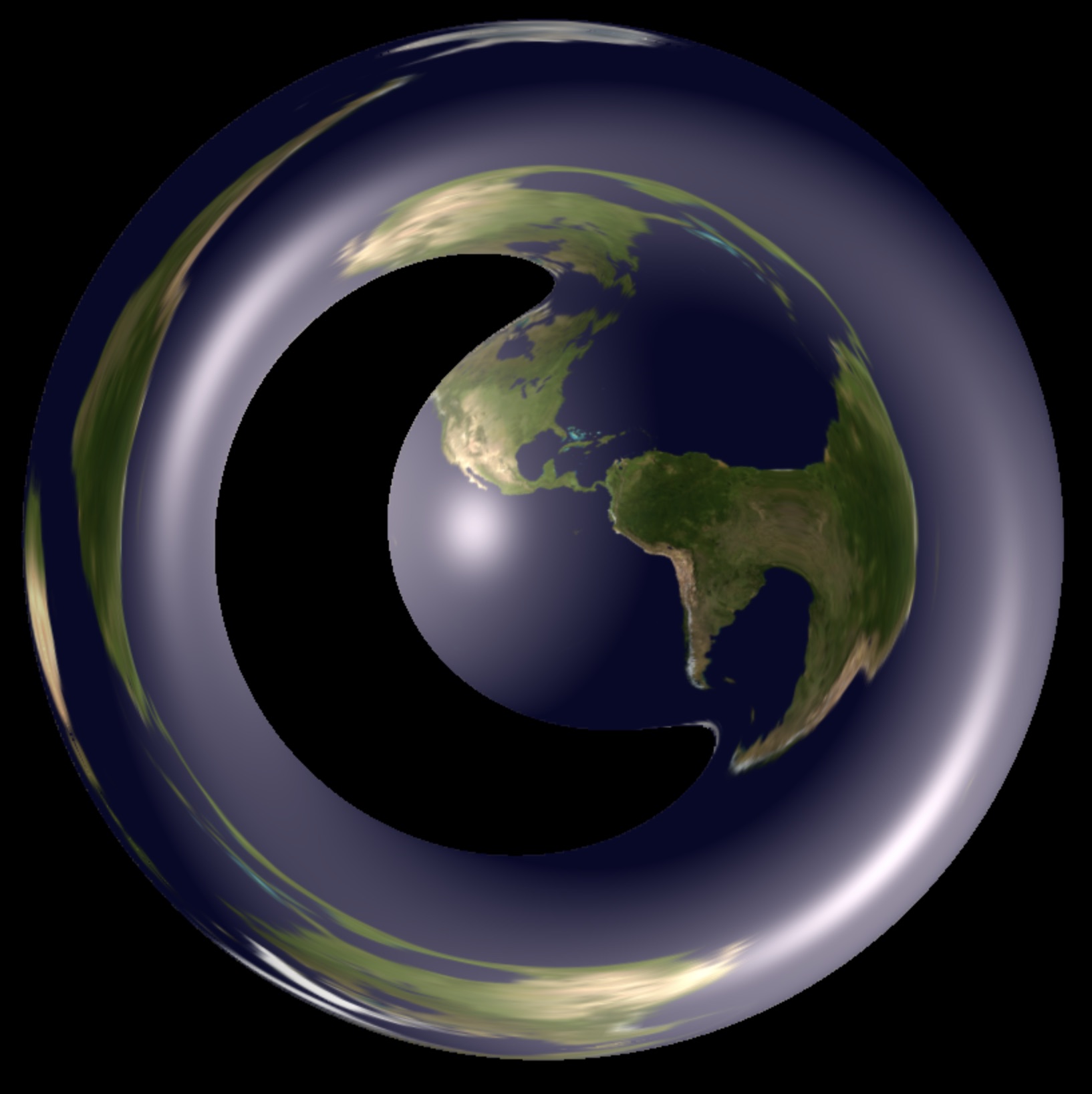
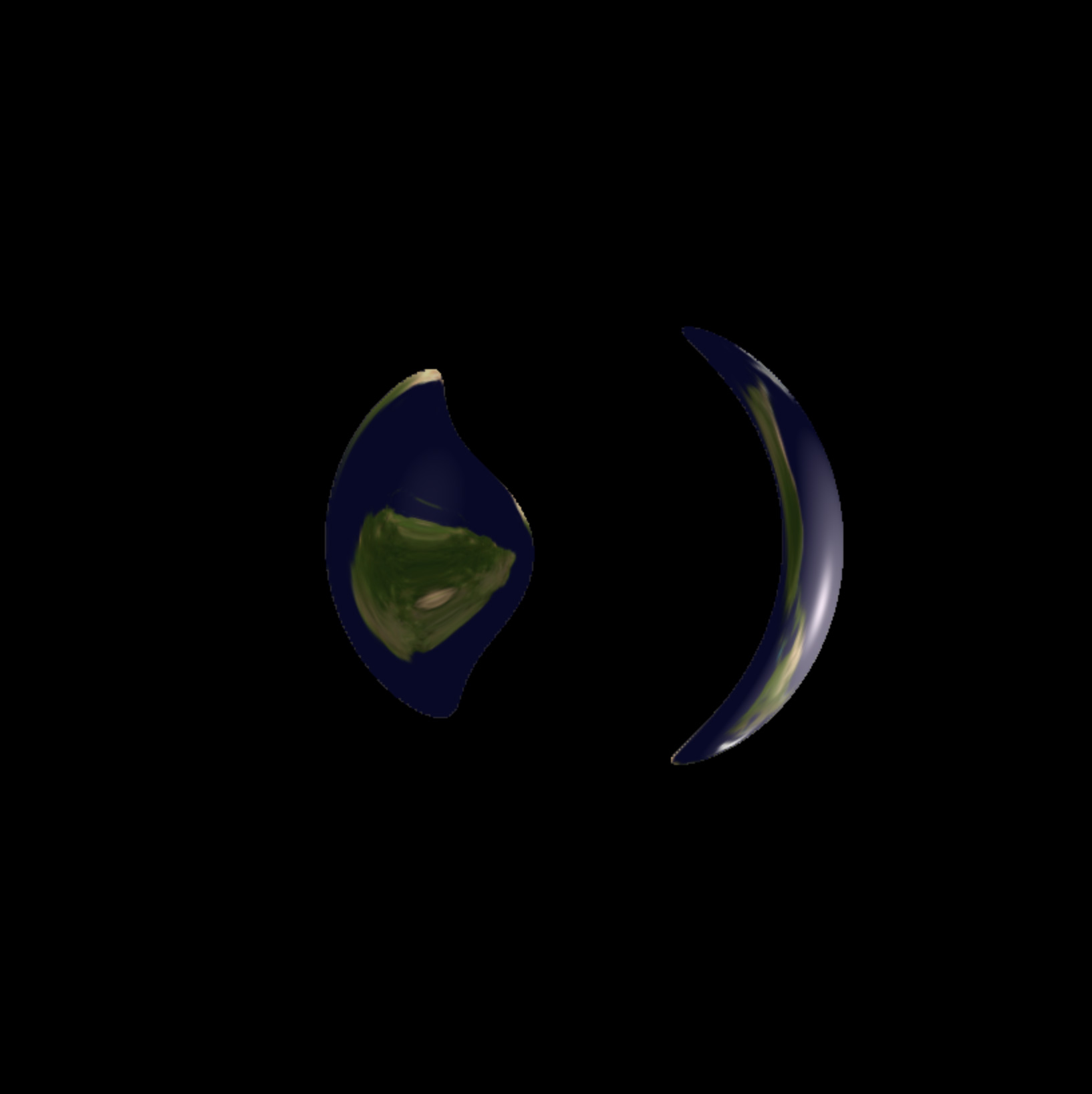
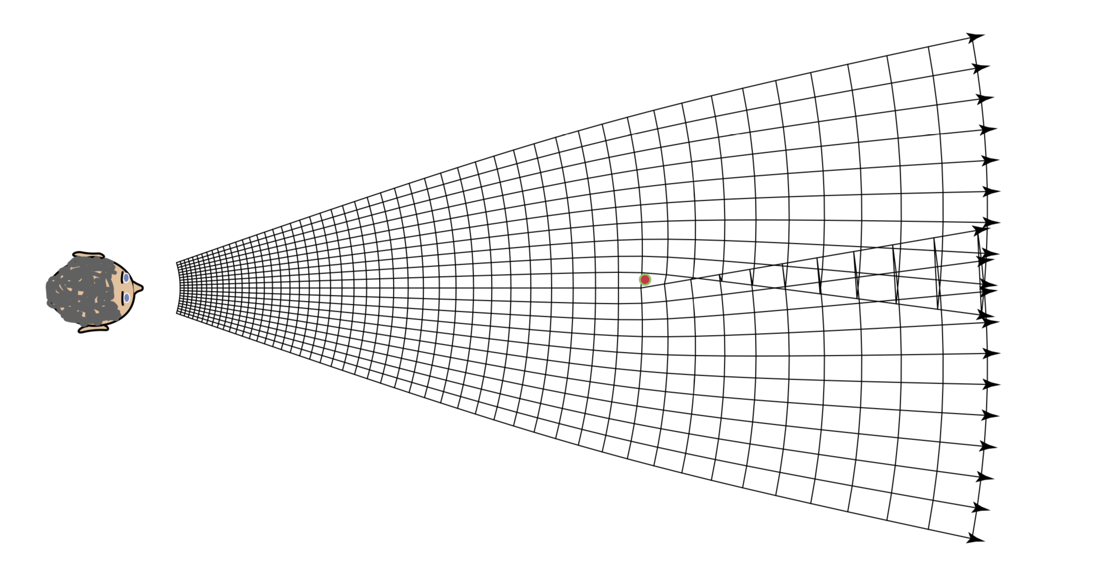
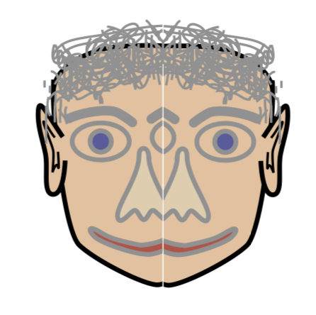
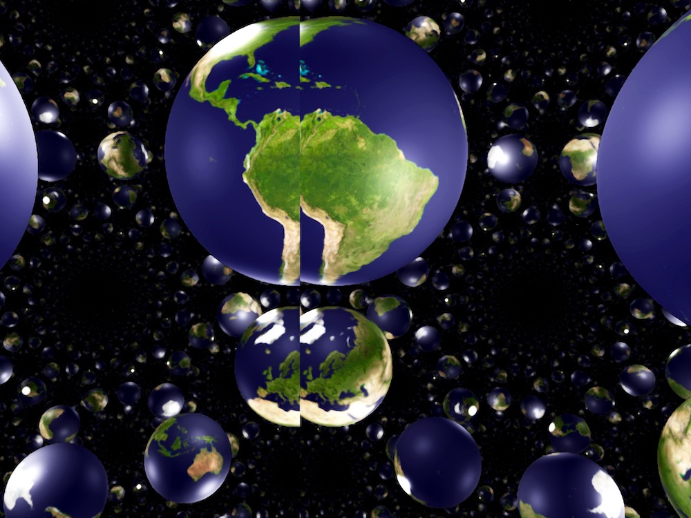
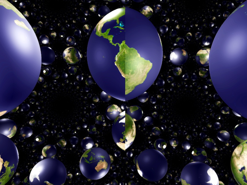
The situation is worse in , Nil, Sol, and , where geodesics “spiral”. Figure 3.3 illustrates how a small parallax in Nil can produce very different pictures: On each row, the scene consists of a single ball textured as the earth. The different images are views of this ball from slightly different positions. Using the convention that one unit represents one meter, the offset between two consecutive images is approximately half the interpupillary distance. Our euclidean brains are not able to interpret the combination of these pictures. One might think that the sphere is too small (a few centimeters) and too far away form the observer (a few meters) for our eyes to see that level of detail. However geodesic rays in Nil spiral in such a way that the angular size of the object in the observer’s view is very large. This makes the object appear as if it is very close to the observer. Thus this parallax distortion cannot be ignored. New ideas are thus needed to produce stereoscopic images in all eight geometries that can be pertinently analyzed by the brain.
Weeks [Wee20, Section 5] uses the following approach in and . The observer is represented by a point in the space . Using the inverse of the exponential map, we send objects in that space to the tangent space based at . We then implement stereoscopic vision using cameras based at two points near the origin of . This works well when the inverse exponential map is single-valued, but seems challenging in the harder geometries.
\stackunder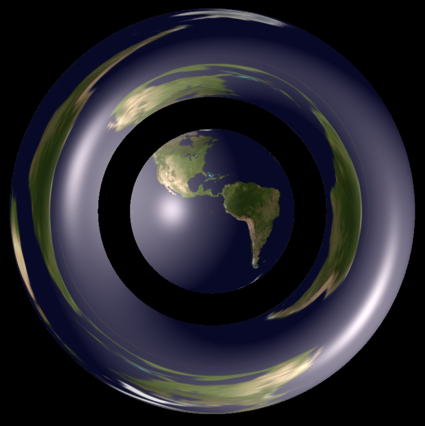 \stackunder
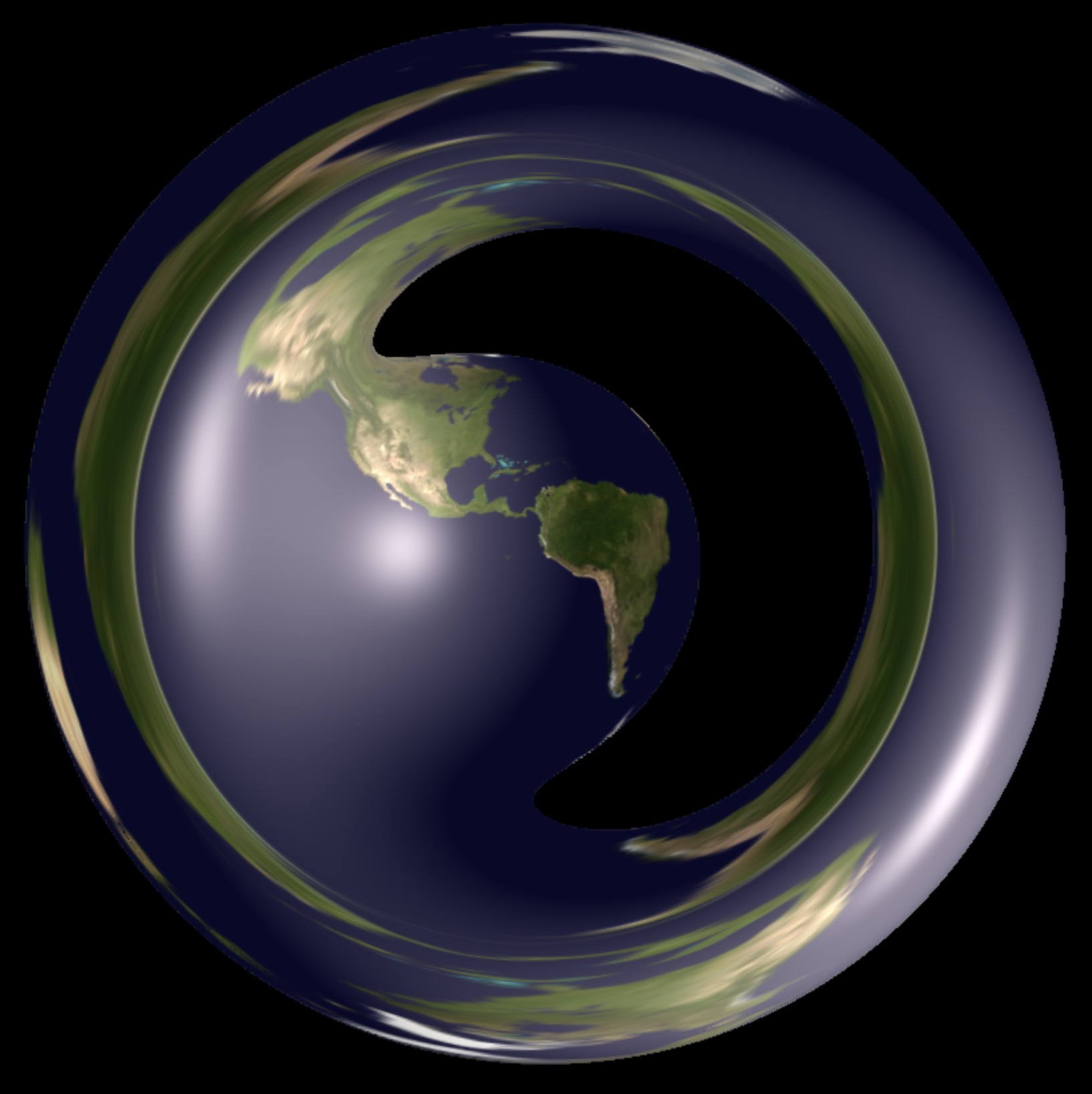
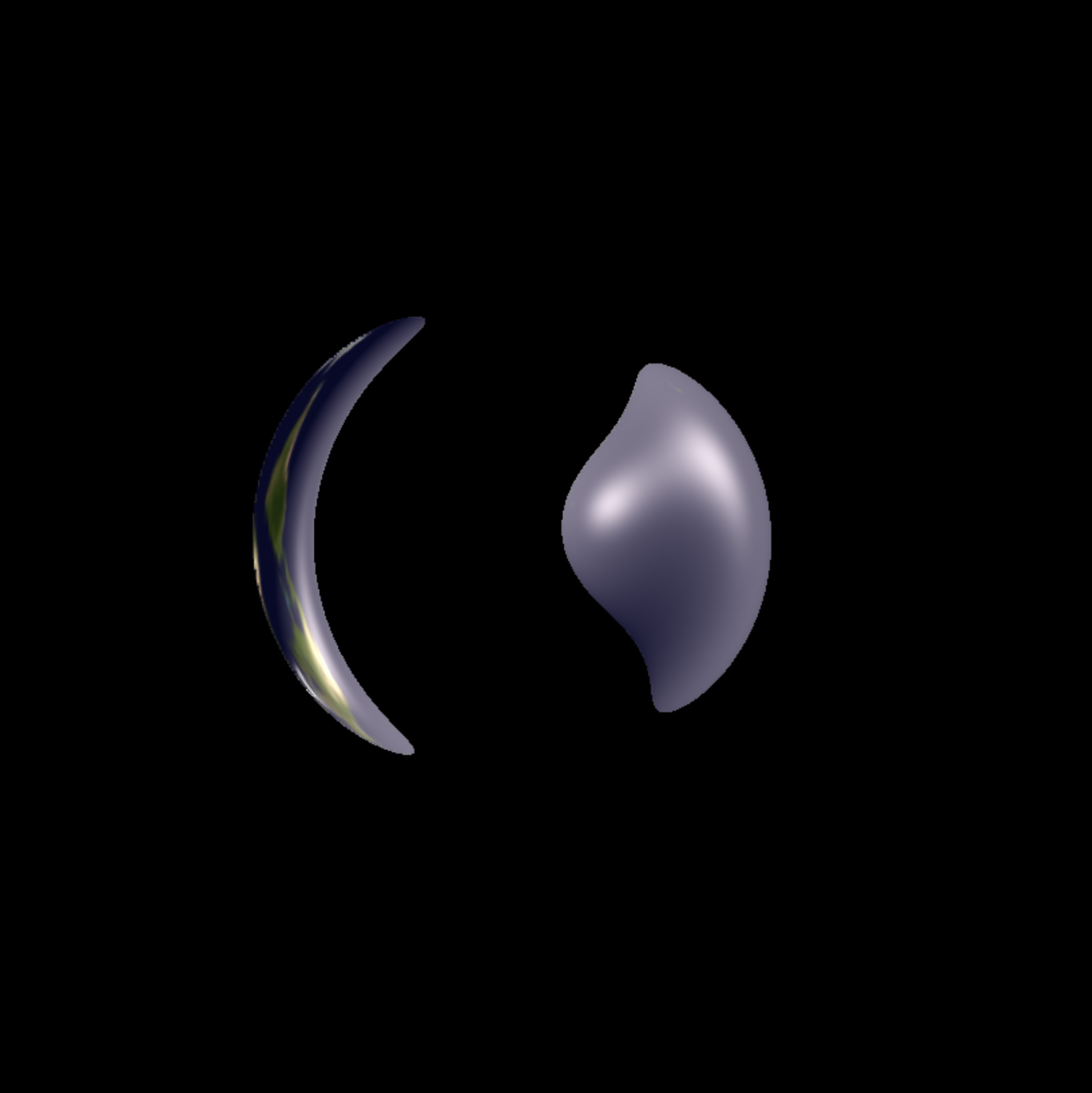
\stackunder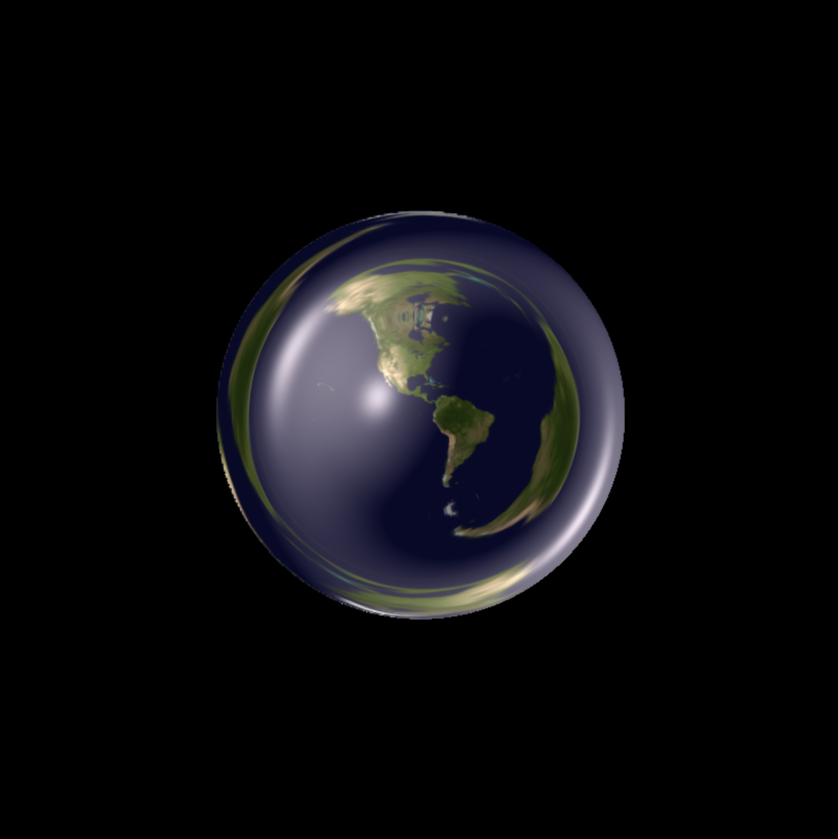 \stackunder
3.7. Signed distance functions in
The algorithms described so far render the in-space view of a scene in the geometry , given a signed distance function for it. In the interest of both simplicity and geometric accuracy, we focus on scenes built from intrinsically defined objects, including
-
•
balls (bounded by equidistant surfaces from a point),
-
•
solid cylinders (bounded by equidistant surfaces from a geodesic), and
-
•
half-spaces (bounded by totally geodesic codimension one submanifolds).
Note that a single object may fall into more than one of the above categories. For example, a hemi-hypersphere of is both a ball and a half-space.
3.7.1. Simple Scenes
In some cases, viewing and moving relative to a single simple object is all that is needed to illustrate surprising features of a geometry. In previous work for example, we qualitatively described counterintuitive features of Nil geometry [CMST20a] with a scene consisting of a single ball, and we studied a single isometrically embedded copy of the euclidean plane in Sol geometry [CMST20b]. From a collection of basic objects, many other simple scenes can be created through finitely many applications of union, intersection and difference. These operations of constructive solid geometry are particularly suited to producing scenes in a ray-marching application, as are faithfully represented on the space of signed distance functions by respectively [Quia].
In many cases however, the interesting features of the geometry are best exhibited by more complex, unbounded scenes, which cannot be built from the basic objects in finitely many operations.
3.7.2. Complex Scenes and Symmetry
Scenes which display interesting features across unbounded regions are useful to highlight various geometric features, including
-
•
exponential growth of volume in negative curvature,
-
•
anisotropy in the product geometries,
-
•
non-integrability of the contact distribution in Nil, and
-
•
the lack of any continuous rotation symmetry in Sol.
The particular details of the scene’s contents do not matter so much as the requirement that the user may travel unbounded distances in any direction and still be surrounded with an approximately homogeneous collection of objects.
One way to do this is to use the homogeneity of to build an extremely symmetric scene, by choosing a signed distance function invariant under the action of a discrete subgroup .
As geometric topologists however, we cannot help but note that covering space theory provides an alternative perspective. Consider a scene invariant under the action of . This is described by a signed distance function with for all . Such maps are in natural correspondence with maps from the quotient .
Indeed, the view from a point of a signed distance function is identical to the view from a lift of a signed distance function invariant under . This follows from the above topological correspondence together with the fact that the covering map is a local isometry.
This suggests exploring the unbounded geometry of indirectly, through the geometry of its quotients .
4. Non-simply connected manifolds
Let be a homogeneous geometry. A -manifold is a smooth manifold together with an atlas of charts
with transition maps in . The elementary theory of such -manifolds shows that one may globalize this atlas into a developing map from to , equivariant with respect to a holonomy homomorphism from to [Gol]. Furthermore, if is geodesically complete, then the developing map is a diffeomorphism and is a quotient, where is the image of the holonomy homomorphism. The simplest -manifold is itself, and we have seen above how to ray-march simple scenes in . Covering space theory implies that is the unique complete simply connected -manifold, but non-simply connected -manifolds abound. Indeed the classification of compact hyperbolic manifolds up to diffeomorphism is still incomplete. Additionally, while there are only ten euclidean manifolds up to diffeomorphism, there are uncountably many distinct euclidean structures in each diffeomorphism class. Simulating not just the Thurston geometry but also various -manifolds is a natural extension of our original goals. These manifolds may or may not have finite volume, corresponding to the discrete subgroups being lattices or not. Generalizing further, our algorithms can also simulate -orbifolds and incomplete -manifolds. Thus we may experience both the three-dimensional homogeneous spaces, and also the atomic building blocks of geometrization.
In the next section, we describe a method to ray-march (or ray-trace) within a quotient manifold, using a fundamental domain. Similar ideas are outlined in [BLV15] and [KCK20].
4.1. Teleporting
Let be a discrete subgroup of , and . To produce an intrinsic simulation of , we wish to reuse as much as possible the work that goes into producing a simulation of . To that end, we describe using a connected fundamental domain with faces . (Alternatively, one could embed in a higher-dimensional ambient space, and try to implement the techniques of Section 3 in that context.) The quotient manifold is obtained by identifying each with via an isometry . These face pairings form a generating set for . This allows us to ray-march using the geodesic flow on , and calculate parallel transport and position/facing using the parametrization of restricted to . Indeed, given a signed distance function pulled back to , the only substantial change is that we must modify the ray-march algorithm to keep the geodesic flow in . We can do this by using the face pairings. Similarly, when the user moves outside of , we move them by an isometry to keep them inside of . In either case, we call this process teleporting. See Figure 4.1.

Remark 4.1.
As a side benefit, the quotient manifold approach helps with floating point errors. At each step of our ray-marching algorithm, the basepoint of our ray is within . In the case that is compact for example, the coordinates of our basepoint are bounded by a function of the diameter of . This then avoids problem (1) of Section 2.4.1. In our experience, we see less noise in images such as Figure 1.1c with this strategy, despite the potential accumulation of errors (see Section 2.4.2) introduced by repeatedly teleporting a ray’s position and tangent vector back inside of . ∎
Remark 4.2.
It may be useful to employ teleporting even when we are simulating a scene inside of the simply connected geometry rather than inside a quotient manifold. That is, we have a discrete subgroup of isometries and a fundamental domain , and we use teleportation to keep the viewer always within . Whenever we teleport the user, we also teleport all other objects in the scene, and update the signed distance function as appropriate. The advantage here is that rays begin inside of , where their coordinates are small. Therefore floating point errors only accumulate to a noticeable degree for objects which are far from the viewer. For some geometries, such distant objects will be very small on the visual sphere. Alternatively, they may be hidden by fog. ∎
4.1.1. Teleporting with a Dirichlet domain
A simple, geometry independent implementation involves choosing the Dirichlet domain for the action of , centered at the origin . To determine whether or not a point is outside of , we compare the distance with for each face pairing isometry . When , the point can be brought back closer to via an application of . Iterating this (relabelling our point as after each step) until , we ensure that is inside of .
An advantage of this approach is that one does not need an analytic description of the boundary to accurately adjust the ray-march. When the intrinsic distance is expensive to calculate however, this adds a significant extra computational burden.
4.1.2. Teleporting with a projective model and linear algebra
A second implementation that removes the need to calculate distances is possible for the Thurston geometries. Up to covers (in the cases of and ), these have projective models: a representation of the geometry as an open subset , together with a linear representation [Mol97].
To lighten the notation in this section, we identify with its image under . We choose our fundamental domain for the action of such that , where is a collection of half-spaces of . The point is outside of if and only if there is a half-space such that . Each half-space of is in natural correspondence with a linear functional , where if and only if , so we can check if by computing the value . The embeddings are inexpensive to compute in our models (see Table 1): for we divide by the fourth coordinate, and , Nil, Sol are already affine patches. The situation for is slightly more complicated, but similar ideas work for the fundamental domains we have implemented. Thus, we reduce the problem to a quick calculation in linear algebra.
Knowing which of the half-planes is not contained in, we now must find the element of which moves back into . We iteratively construct this element from the for which (at each step) . In many cases (for example when is a finite index subgroup of a reflection group), it does not matter which such we choose at each step. In other cases, for reasons of efficiency, one must be more careful with the ordering, see for example Section 9.9.
Since we have projective models for the eight Thurston geometries, we use this strategy rather than the Dirichlet domain strategy.
Remark 4.3.
In practice, when using the projective model we can take to be an arbitrary generating set for . We then generate the half-spaces from . Their intersection forms a fundamental domain . Note that multiple faces of may lie in the boundary of a single half-space, and the face pairings of may involve elements of other than those in . However, we need only use elements of to implement teleportation. See Section 9.9 for a detailed example. ∎
4.2. Signed distance functions in
With the addition of teleportation, we may draw scenes in any complete -manifold using the same algorithms as we use in itself, given the input data of a signed distance function mapping to describing the scene. Unfortunately, efficiently calculating a signed distance function (or even a distance underestimator) for a scene in a quotient manifold is often non-trivial. In practice, we will often use an approximation.
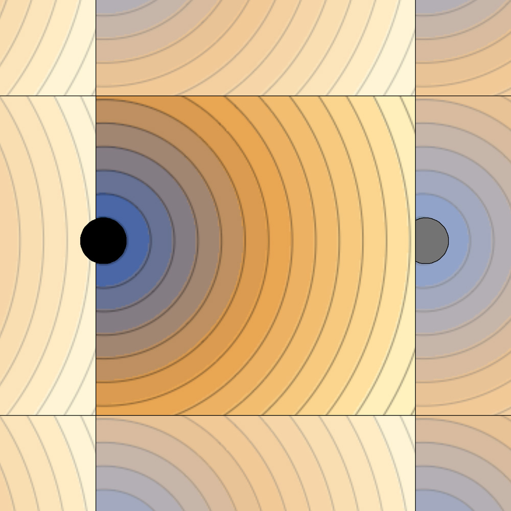
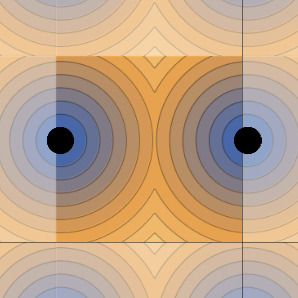
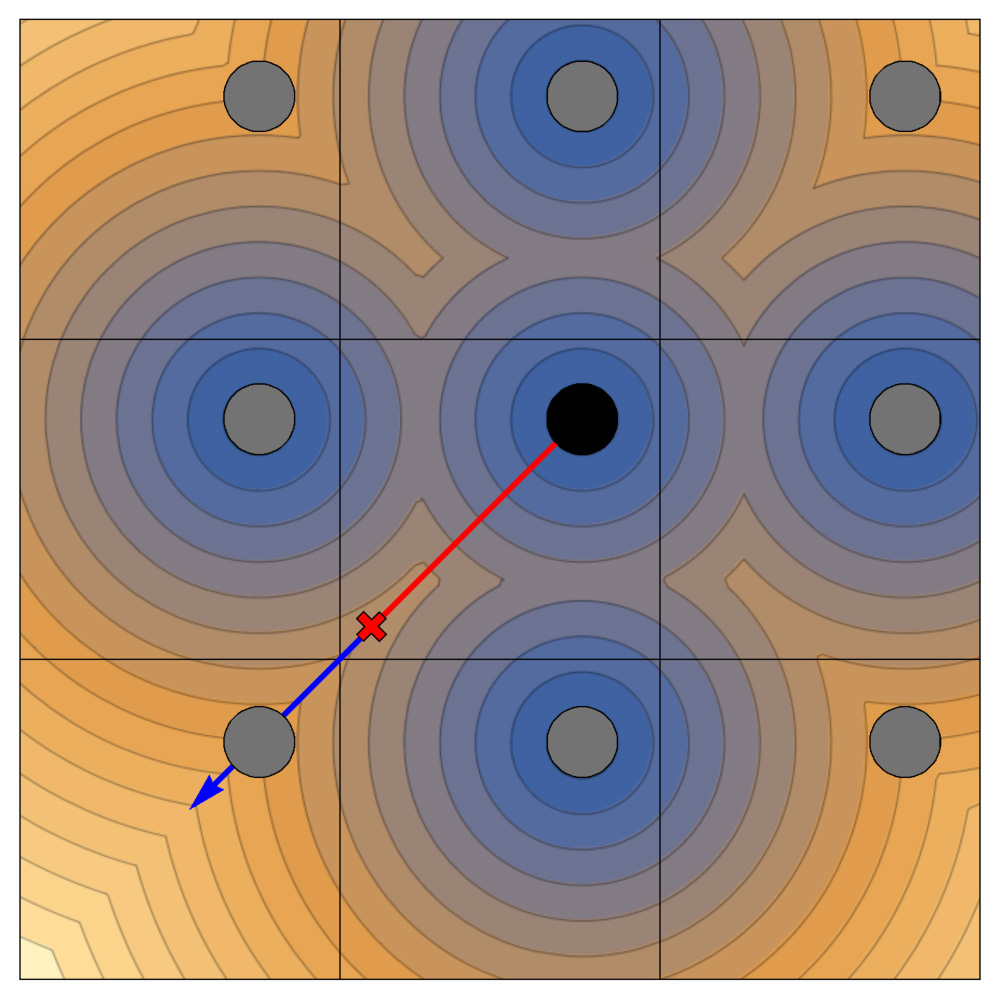
We can construct a very simple approximation for a scene as follows. Let be a fundamental domain for the quotient manifold . We then view as a subset of . For a point , we may then return the signed distance from to , where we measure distance in , ignoring the quotient manifold structure entirely. Let us call this simplest approximation . (Here we implicitly extend the signed distance function from to .)
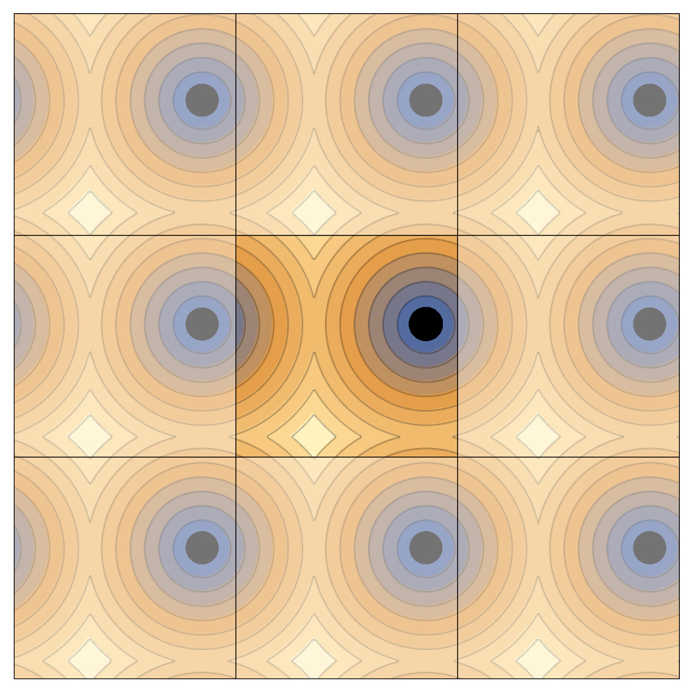
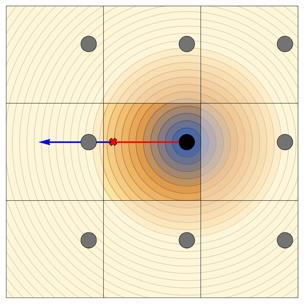
As an example, Figure 4.2a shows the correct signed distance function for a disk in a square torus, while Figure 4.2b shows . For such a square torus, will be the correct signed distance function for the quotient torus only if the disk is centered in the square. Using in place of the correct signed distance function can lead to some serious visual artifacts. For example, consider a ray starting at the position marked with a small red “” in Figure 4.2b and heading to the left. This ray should leave through the left side of , teleport to the right side of , then hit the disk. However, the function reports that the distance from to the disk (indicated with the red interval) is more than half the width of the square. A march along the ray by this distance is shown with the blue arrow: we jump straight through the disk. The result is that this lift of the disk is invisible when viewed from .
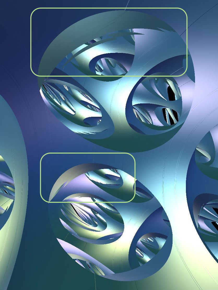
A similar but less extreme form of visual artifact is shown in Figure 4.3a. Here we see jagged errors on the boundaries between cells. In some places near the boundary of we erroneously jump through points of the scene. Whether or not we make such a jump depends on how close to the boundary of we land before jumping across the boundary. The variability in this leads to the jaggedness. Figure 4.5a shows related artifacts.
4.2.1. Creeping over the boundary of
One strategy to avoid these kinds of errors uses the observation that flowing by the distance given by is only dangerous if our ray leaves . Thus, we should detect when a ray passes outside of , and stop just outside. As usual, we are teleported back inside of , and continue ray-marching.
Detecting when a ray hits is a similar problem to that of detecting when the ray hits an object in the scene. We employ a variety of different methods, as follows.
-
(1)
One way to do this is to use ray-tracing: we solve for the intersection between the ray and the boundary, and measure the distance between this intersection point and the start of the ray.
-
(2)
If it is difficult to solve for this point of intersection, but the faces of have computable signed distance functions, then we can instead use ray-marching. We flow by the minimum of and the distance to .222In practice, we allow a march of the distance to the nearest wall plus some small : this prevents wasting many steps approaching the boundary to no appreciable theoretical disadvantage: the teleportation scheme returns us to immediately upon overstep.
-
(3)
When the faces do not have computable signed distance functions but we can still detect whether or not we are inside of , we proceed as follows: We flow by the distance given to us by , and ask if the result puts us outside of . If it does, then we perform binary search on the distance we flow to find a point just outside of .
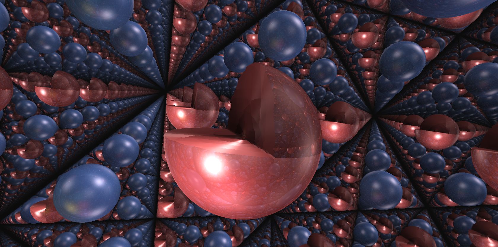
Creeping just over the boundary solves the problem shown in Figure 4.3a, giving the correct image, Figure 4.3b. In general, creeping produces the correct pictures as long as all objects in the scene are contained within the domain . However, this breaks down if we wish to, for example, move a ball from one domain to another. When a ball intersects , calculating the approximation requires measuring the distance to the center of the ball in , and at least one translate of its center under some element of . See Figure 4.4. Without this extra calculation, one sees objects cut in half by the boundary of . See Figure 4.5b. Solving this problem led us to the following alternate (or additional) strategy to creeping.
4.2.2. Nearest neighbors signed distance functions
Here we use a signed distance function on that takes into account the effects of the nearby translates of .
Let be a set of isometries. Define
For example, is just , and is the correct -invariant signed distance function. If is infinite, then we cannot calculate directly. However, if the tiling of by copies of the fundamental domain is locally finite, then there is a finite subset such that and are equal on . Indeed, we may choose for the set of all such that the distance from to is at most the diameter of . Depending on the shape of the fundamental domain and how it is glued to itself however, the size of may be large. If so, calculating this signed distance function may be prohibitively expensive.
We find that most visual artifacts can be resolved without the use of creeping by using , where . That is, we use in and its nearest neighbors, directly connected by face pairings. See Figure 4.5c. In some circumstances this may not be enough; see for example Figure 4.6. Here a ray passing close to a vertex of the tiling may not see an object diagonally adjacent to the starting domain. In three dimensions the equivalent problem can appear for rays crossing close to an edge of the tiling.
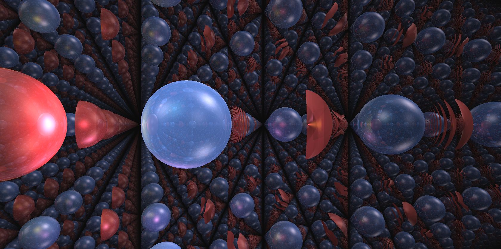
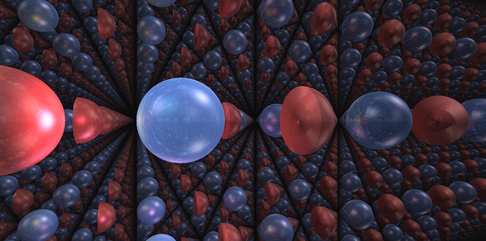
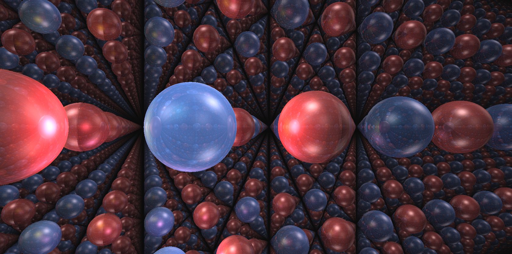
In general, depending on the circumstance, either creeping or using a nearest neighbors signed distance function, or some combination of the strategies may be the most efficient strategy to obtain correct images. Even the combination of both strategies can produce errors in some circumstances. In Figure 4.7, the only solution would be to use more translates of than just the nearest neighbors.
Remark 4.4.
We would like to choose a scene for which illustrates the geometry and topology while having a signed distance function that is very efficient to calculate. We often use the following strategy. We delete from a fundamental domain a large ball (or solid ellipsoid). The signed distance function for the complement of a ball in is
Here is a sufficiently large radius so that the deleted ball opens windows into neighboring fundamental domains. The corresponding tile for the cubic lattice in is shown in Figure 2.1b. Depending on the geometry, we may also remove a sphere centered at each vertex of the fundamental domain, as in Figure 2.1c. ∎
4.3. Orbifolds and incomplete structures
In our discussion so far we have assumed that is a manifold, but in fact nothing is lost by generalizing to orbifolds. Briefly, an orbifold is a topological space locally modeled on patches of for some finite group of diffeomorphisms. When is the trivial group, this reduces to the definition of a manifold. This additional flexibility in the definition allows for certain controllable singularities, such as cone axes (with cone angle for some integer ), while still behaving very similarly to the manifold case. Indeed, many topological notions such as fundamental groups, covering spaces, and geometric structures carry over directly to orbifolds. Geometric structures on orbifolds are defined similarly to those on manifolds (see the beginning of Section 4), with the main difference being that the action of the fundamental group under the holonomy homomorphism need not be free. However, as the image of the holonomy homomorphism is still discrete, we may find a fundamental domain for its action and draw pictures of the quotient orbifold as before. There is however little change in visual effect: by [CHK00, Corollary 2.27], every orbifold with a structure is finitely covered by some manifold. Thus, up to a finite amount of local information in the scene, the large scale picture will look the same as its manifold cover.
We can generalize still further. Manifolds and orbifolds have complete geometric structures, meaning that the developing map is a diffeomorphism. This allows the identification . The more general notion of incomplete -manifolds are also fundamental objects in geometric topology. Allowing general immersions as developing maps naturally captures various kinds of singularities, such as cone axes (where the cone angle can now be any real number) or punctures. This sort of flexibility is crucial in some core results of geometric topology. For example, the natural extension of the Geometrization Theorem to orbifolds requires the analysis of incomplete hyperbolic structures. However, incomplete structures are typically difficult to deal with, as the image of the holonomy homomorphism is indiscrete. Previous work here includes hand-drawn examples by Thurston (including two-dimensional structures in chapter three of [Thu97], and a three-dimensional drawing reproduced here in Figure 4.8a from [Thu98]) and tilings of by Bonahon [Bon09].
Our ray-marching procedure for quotient manifolds extends without change to incomplete structures, allowing the accurate rendering of these as well. Note that throughout the algorithm, only local data is required: the existence of a fundamental domain and face pairings . Both of these exist equally well for incomplete structures. Here the inside view is quite different than the complete case. The ability to render incomplete structures may aid in visualization projects, such as animating hyperbolic Dehn surgery or geometric transitions. Indeed, version 2.8 of SnapPy [CDGW] implements the inside view of hyperbolic manifolds undergoing hyperbolic Dehn surgery. However, interpreting these requires more mathematical sophistication than for more familiar manifolds and orbifolds, so we will not focus on them in this paper.
Remark 4.5.
We create some of our spaces by directly constructing a fundamental domain , then later figure out which manifold, orbifold, or incomplete manifold it is. In other cases, we start with a desired manifold, or lattice , and have to work out a fundamental domain . For the easier geometries, this generally involves (spherical, hyperbolic, or euclidean) trigonometry. We discuss the construction of fundamental domains for the harder geometries in Sections 9.9, 10.9, and 11.7. ∎
5. Lighting
Common physics-based shading techniques in computer graphics (diffuse and specular lighting, reflections, shadows, ambient occlusion, and atmospheric effects) are all computed from geometric data, and so generalize naturally to riemannian geometry. Below we briefly review some of these techniques, and the modifications required. Also see [NdSV20b] for a path-tracing lighting model in the constant curvature spaces.
The effect from each light source in the scene can be computed separately, and the final color determined through a weighted (by intensity) average of each light’s contribution. Thus it suffices to describe the contribution of a single light source. However, in the geometries with positive sectional curvatures (, Nil, Sol, ), non-uniqueness of geodesics may cause even a single light source to illuminate an object from multiple directions. As these individual contributions also combine linearly to the total, we may further reduce the problem to understanding single-source lighting from a single direction at a time.
2pt
\pinlabel [l] at 102 335
\pinlabel [tr] at 110 293
\pinlabel [tr] at 148 190
\pinlabel [tr] at 214 129
\pinlabel [t] at 254 55
\pinlabel [b] at 263 147
\pinlabel [bl] at 299 127
\pinlabel [tl] at 323 100
\pinlabel [tl] at 390 103
\pinlabel [tl] at 439 165
\pinlabel [r] at 480 203
\endlabellist
To fix notation, let be a scene in given by a signed distance function , lit by a light source at . See Figure 5.1. Let be the base color of the point of the scene, (represented as a three-vector storing its red-green-blue components), let be the color of light source, and be its intensity. Now suppose that we are at a point , looking in the direction . Assume that this line of sight ends by impacting the point of the scene. To compute the aforementioned lighting effects, we need the following data:
-
•
: unit outwards normal to at ,
-
•
: unit vector at pointing to ,
-
•
: reflection of with respect to ,
-
•
: unit vector at pointing to ,
-
•
: unit vector at pointing to ,
-
•
: unit vector at pointing to ,
-
•
: distance from to along the geodesic with tangent ,
-
•
: distance from to along the geodesic with tangent , and
-
•
: the light intensity experienced at from the direction .
Here we employ the convention that vectors in the tangent space at are written in upper case, while vectors in tangent spaces at other points are written in lower case.
Remark 5.1.
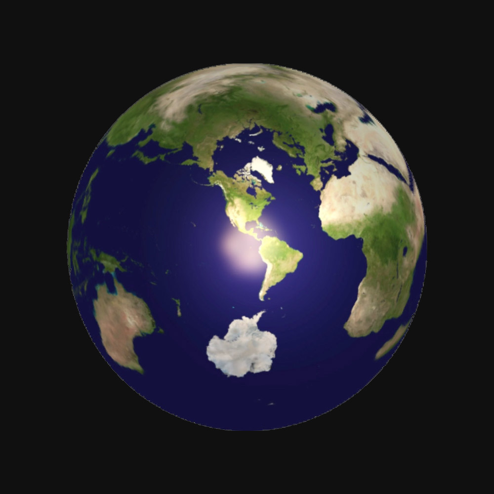
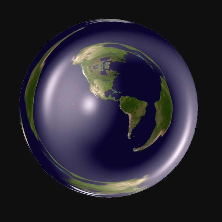
The base colour for a point of the scene can be a single colour for each object, or we can texture objects in a more complicated way. For example, we sometimes texture balls as the Earth. This provides a globally recognized coordinate system and allows one to infer the final endpoints of geodesics leaving your eye. See Figure 5.2. ∎
5.1. Phong lighting model
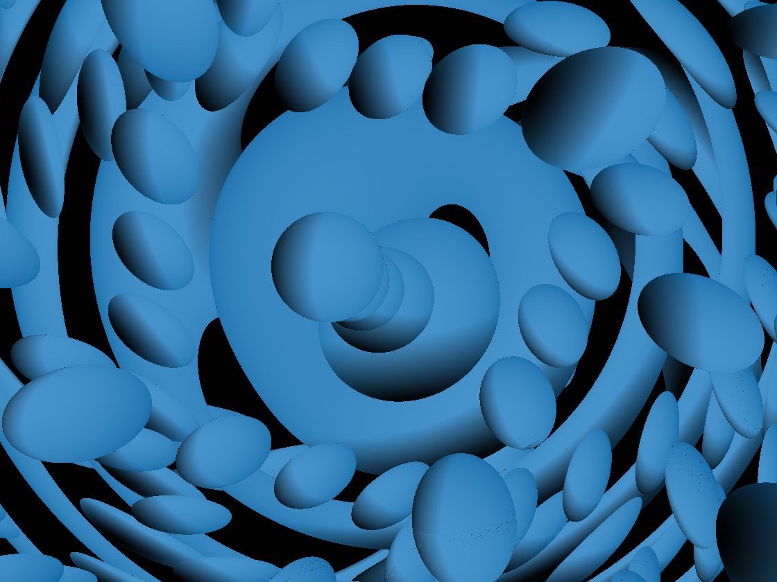
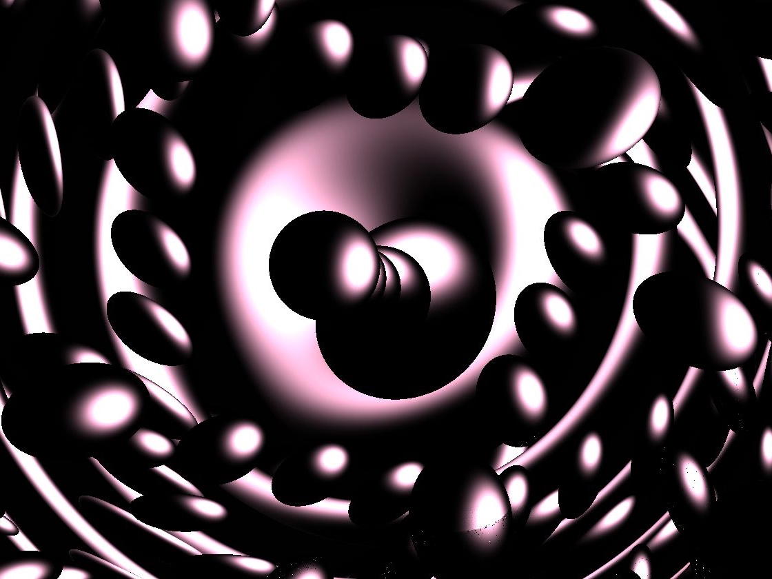
An empirical formula for accurate diffuse and specular reflection in computer graphics was published by Phong in his 1975 dissertation [Pho75] and now bears his name. The Phong lighting model (also called the Phong reflection model) decomposes the total color of the surface as a sum of three components: ambient, diffuse and specular. The ambient contribution is simply the base color of the object at . The remaining two terms are proportional to the light color and the intensity of the light source, as well as a third geometric quantity, as follows. Diffuse lighting is also proportional to the cosine of the angle between the light direction and the surface normal. Specular reflection is proportional to some power of the cosine of the angle between the viewer and reflected ray directions. This power is a parameter controlling the “shininess” of the material of the object. When either of these angles is obtuse, the corresponding lighting contribution is taken to be zero. This allows us to express the total lighting contribution of Phong lighting using the riemannian metric at :
| (5.2) |
where the constants are chosen to satisfy . These control the relative contribution of each of these factors.
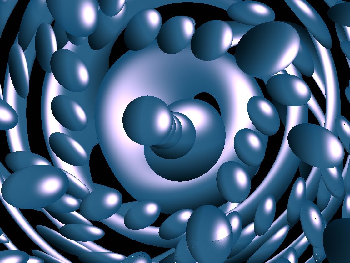
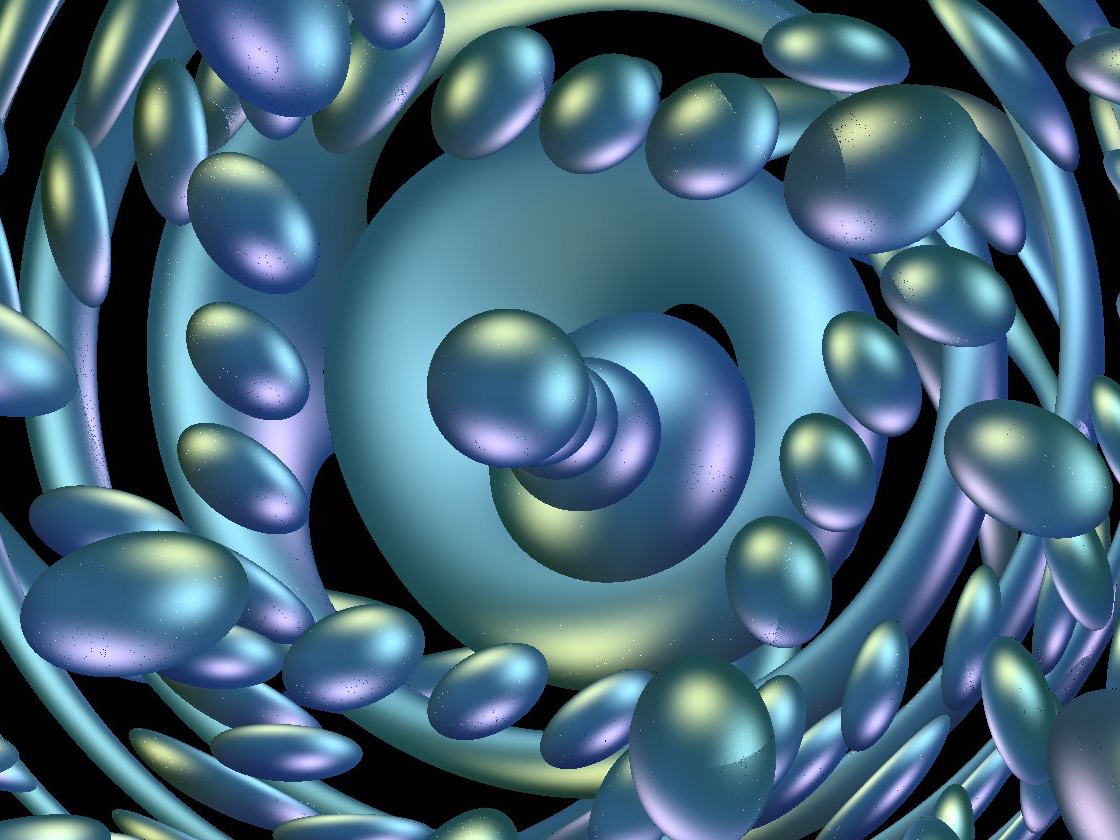
Remark 5.3.
Phong justifies his model empirically, by comparing a render with a real-life photograph of a (euclidean) scene. We use his model far outside of the setting in which it was designed for, so one could question whether or not it produces accurate results in our non-euclidean spaces. A reasonable test would be to compare our results with a more physically correct ray-tracer. ∎
5.2. Shadows
Phong lighting calculates the contribution of the observed color at due to a light source in the direction using only local computations in . While efficient, this ignores the existence of other objects in the scene, effectively rendering them transparent to the lighting calculation.
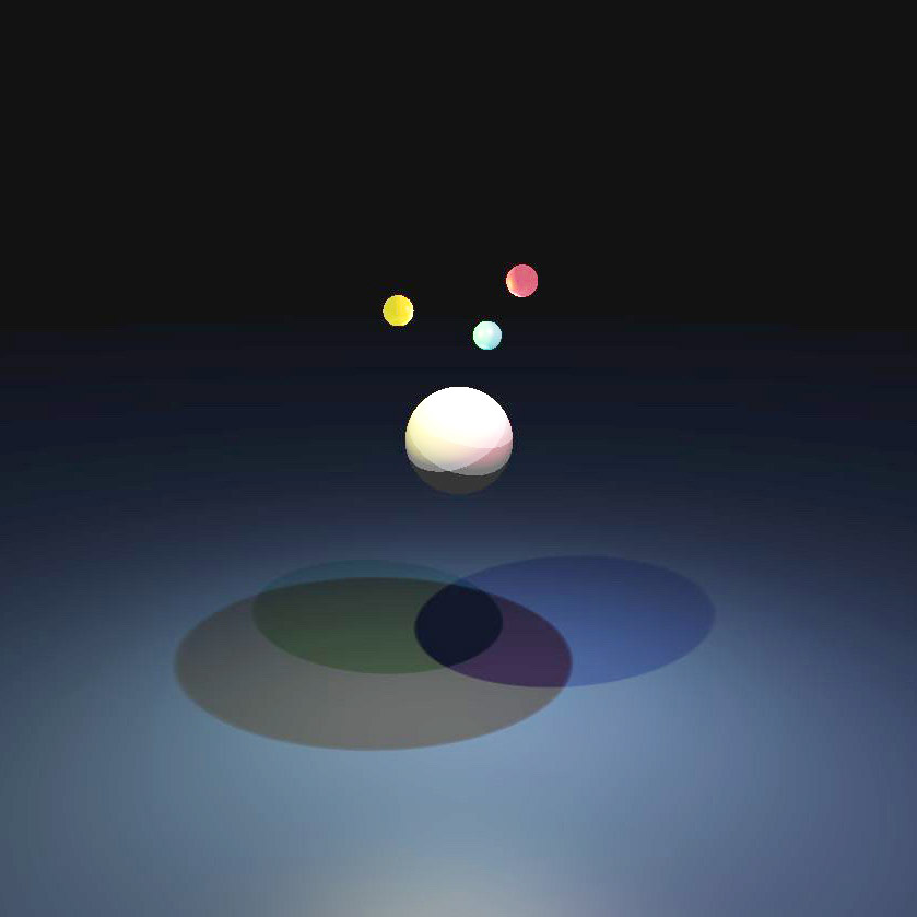
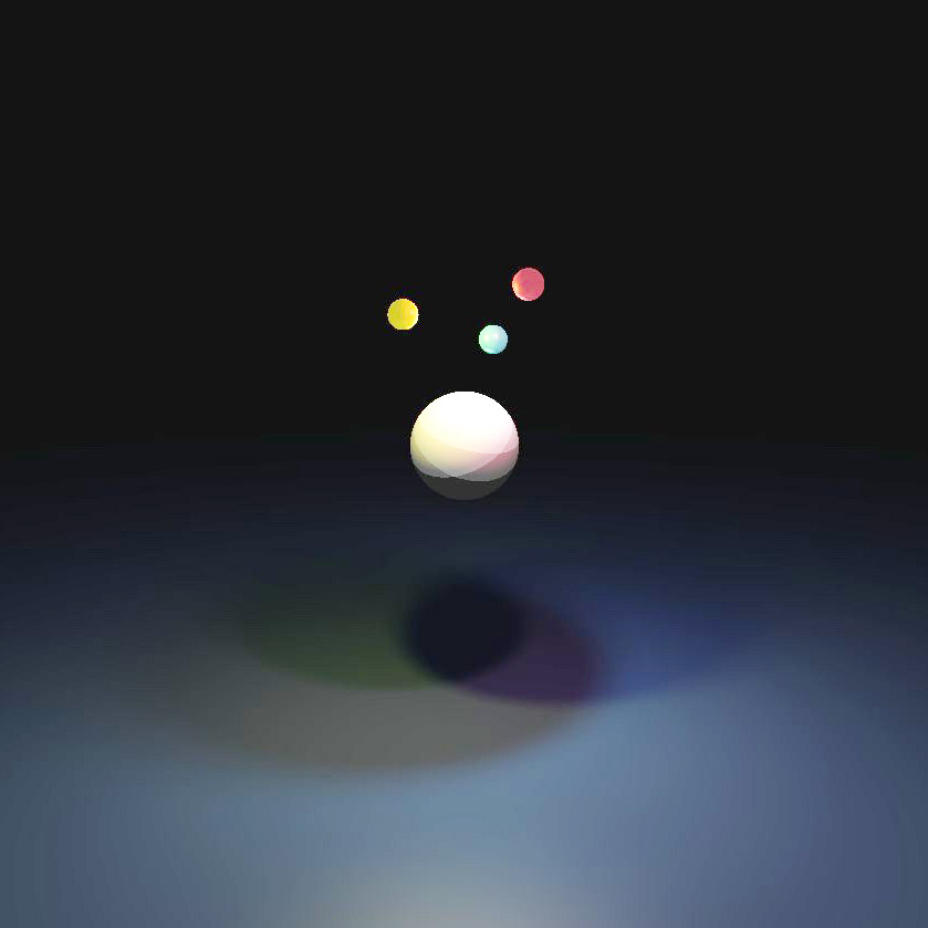
Happily there is a simple solution to detecting objects which block the path from to the light: simply ray-march starting at in the direction towards the light and see if you hit anything. If you do then there is no need to calculate the Phong lighting contribution for that light/direction, as is in shadow. When modeling lights as point sources, this produces hard shadows. Realistic light sources which emit light over an area instead produce soft shadows, as there are points in space where the light source is only partially obscured. While modeling an extended source is computationally demanding, a multitude of empirical formulas for approximating soft shadows with point source lights have been developed in computer graphics. We briefly discuss a solution particularly well suited for ray-marching below. See [Quib] for more details.
Instead of a simple binary value, the shadow is modeled as a scaling factor to be multiplied by the Phong lighting contribution, smoothly interpolating between zero and one. To compute this value, we track the distance of the light ray from other objects in the scene as we follow it backwards from in the direction . Let be the arc length parametrized geodesic from to the light at with initial tangent . The degree of shadow imparted by the surrounding scene at a point is modeled by the distance of from an object in the scene, normalized by the distance traveled from . The total degree of shadow is proportional to the minimal value of this ratio over the path, or
| (5.4) |
Here is a parameter determining softness. As this reproduces the hard shadows above. In practice, we approximate this by computing this ratio at each step of the ray-march from to , and then take the minimum.
5.3. Atmospheric Effects
The fact that computing the total distance traveled along a path is trivial in a ray-marching application makes the above soft shadow approximation efficient. This almost free availability of path lengths also lends itself well to volumetric rendering: accounting for contributions to the lighting from atmospheric media encountered along the path. The simplest such effect, distance fog, is computationally inexpensive to implement and provides helpful distance cues in complex scenes. This replaces a fraction of the color of a pixel with a “fog” color, , depending on the distance the ray travels before hitting an object.
In many computer graphics applications, this fraction is linear in path length. This has the advantage that there is a distance at which all of the pixel is given the fog color, and no further calculation is necessary. However, a physically realistic model based on scattering along a path (the Beer-Lambert law in physics) implies that the fraction is actually exponential in the path length. We give these two models below.
| (5.5) |
Here is a constant determining the rate of scattering. Each of these are extremely easy to implement, as they are standard functions of the already-available path length.
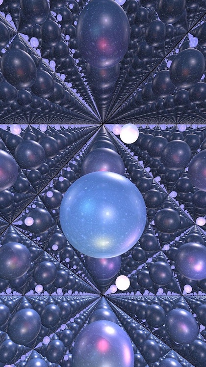
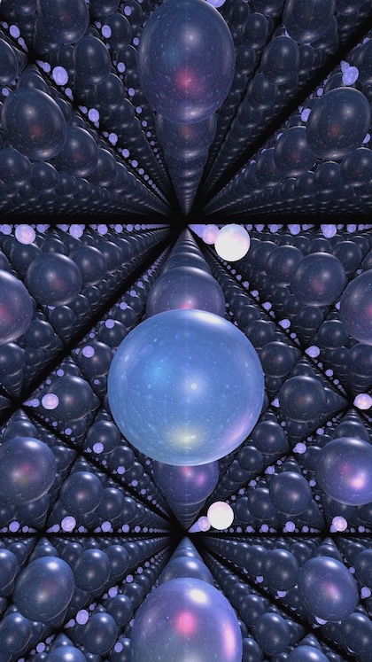
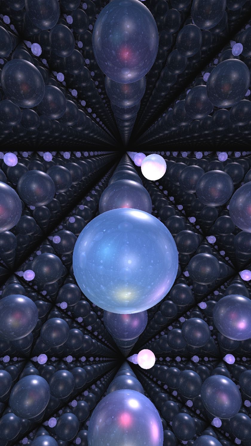
Combining the contributions from both shadows and fog, we obtain the following.
| (5.6) |
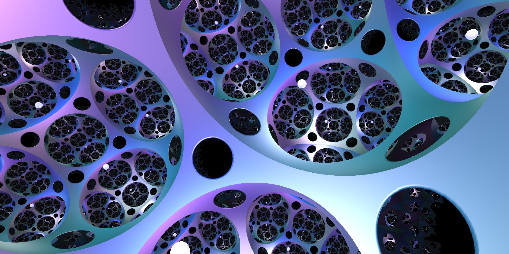
Outside of this section, our in-space images use exponential fog unless otherwise noted. We always set to be black.
5.4. Reflections
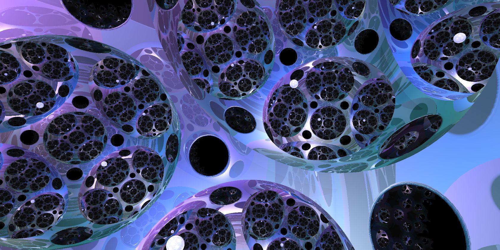
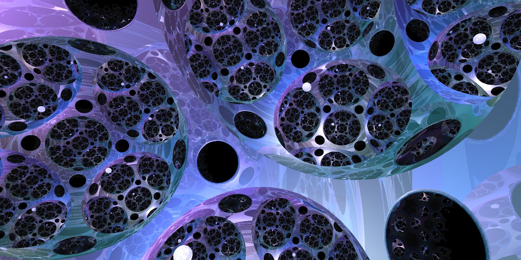
It is also relatively simple to allow for reflective materials in ray-marching, Upon impacting a reflective surface at , one simply initiates a new ray-march from in the direction of the reflected ray. This ray-march may impact another object, at say. If so, we may reflect again. Computing the observed colors at the points as above, the final color is an average, weighted by the reflectivity of the material at . This can be carried out iteratively with no additional difficulty (other than increase in computation time). The weighted averages for one and two reflections are given below.
5.5. Computing the necessary geometric quantities
As the above sections illustrate, it is relatively straightforward to calculate accurate lighting, given the geometric quantities listed at the beginning of this section. Here we turn to the issues involved in computing these. Some of these quantities are available directly from the ray-march itself.
5.5.1. Computing
The vector pointing from the viewer to the observed point is the initial tangent vector for the ray-march.
5.5.2. Computing
The vector pointing back at the viewer is the negation of the final tangent vector for the ray-march.
5.5.3. Computing
The distance from the viewer to the observed point is the path length returned by the ray-march.
Other quantities require further computation.
5.5.4. Computing
The unit surface normal is computable directly from the signed distance function . It is the gradient vector dual to via the riemannian metric. As in multivariable calculus, fixing a basis for , this is approximated for some small by
While in principle any choice of basis of suffices, even slight discontinuities in the normal field over a surface are plainly visible in the output of the Phong lighting model. To prevent this source of error, we make a globally continuous choice of basis by selecting a section of the frame bundle. A simple construction of such a section follows from the transitivity of the -action. Let be a subset (not necessarily a subgroup) of the isometry group such that the orbit map defined by is a diffeomorphism. (For example, when has a subgroup acting simply transitively, we may take this as .) The inverse of this orbit map provides a section with image , sending to . We promote this to a section of by choosing an orthonormal frame for and translating by the -action. This assigns to the frame .
5.5.5. Computing
The unit normal provides a means of reflecting rays in the surface. Given any vector we may compute its reflection in the surface by
Thus, given the direction to the light source , we may find the final direction needed for Phong lighting, . This leaves only four quantities to be computed, all dealing with the location of the light source; two directions and two scalars . These require global information about the geometry of . We discuss this next.
5.6. Computing lighting directions, , , and distance
Calculating the direction in which a light is visible from a point on the surface (and the other related quantities) cannot be reduced to linear algebra in some tangent space: it involves the global geometry of . This requires a procedure that takes two points and returns the set of lighting pairs . Here each element represents the direction, , of a geodesic connecting to , and the length, , of the geodesic segment connecting to . Since we use explicit formulas for the geodesic flow, one can directly compute from the direction and the reverse geodesic joining to . In all cases, we may use the homogeneity of to reduce the problem to understanding geodesics from the origin, and focus on calculating the lighting pairs for . However, for the convenience of the reader, in the isotropic and product geometries we provide formulas for a general point .
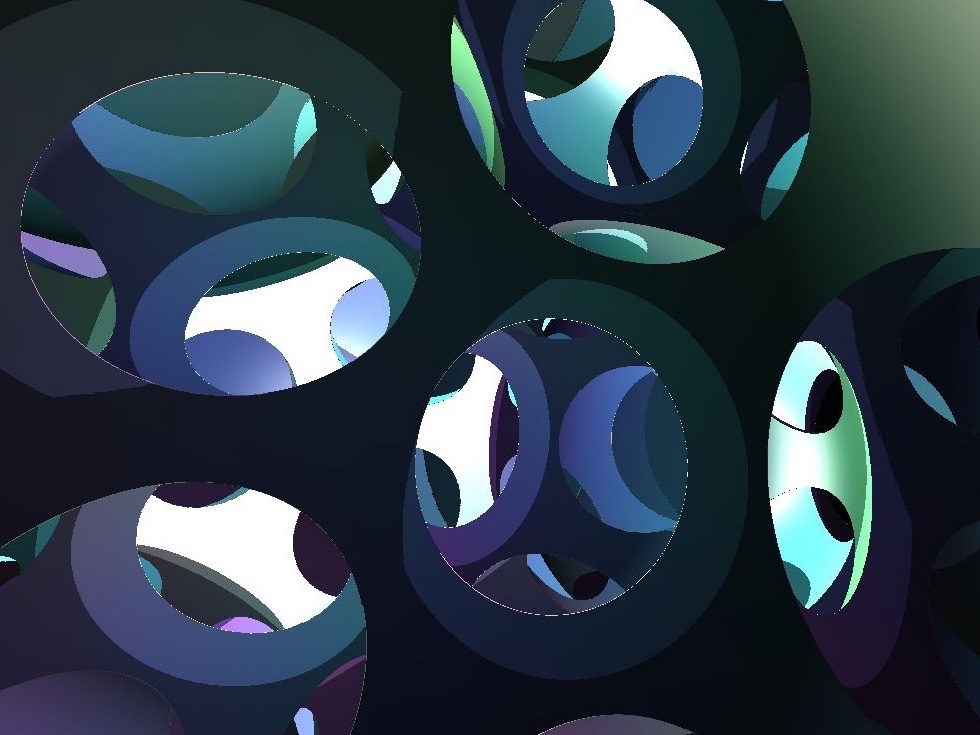
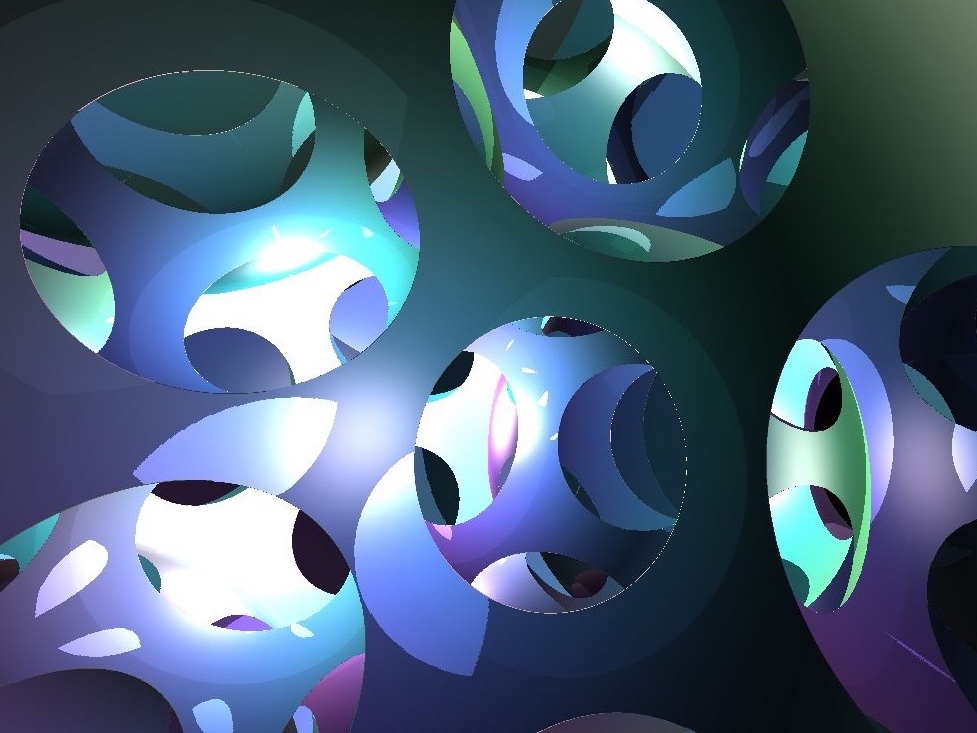
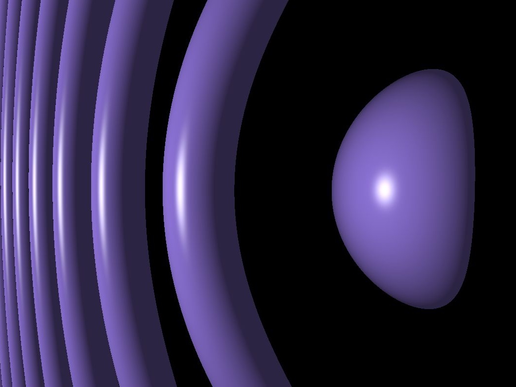
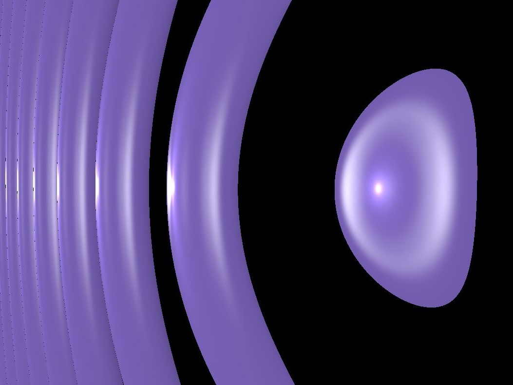
In geometries with nonpositive sectional curvature, geodesics are unique by Cartan-Hadamard. Thus for each the set is a singleton. In other geometries may be a singleton, finite, countably infinite, or uncountably infinite, depending on . See Figure 5.7b for examples of lighting along multiple geodesics in and . There is no uniform approach to calculate , so we deal with this computation in later, geometry-dependent sections of this paper.
5.7. Computing the light intensity
We have one remaining quantity to compute: , the intensity of the light source at , as observed at from direction . We model our light source as isotropic with constant intensity . To fix some notation, for any distance and unit direction vector , let be the intensity arriving from the light source after traveling along the geodesic ray in the direction for distance . For any solid angle (that is a subset of the unit tangent sphere at denoted by ), let be the surface formed by flowing outwards from along geodesics in the directions in by distance . See Figure 5.8.
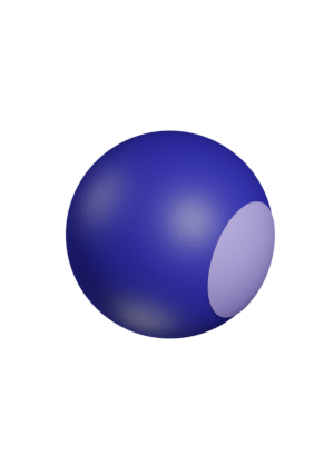
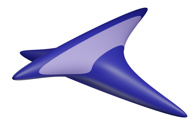
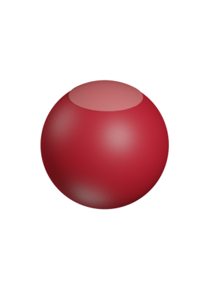
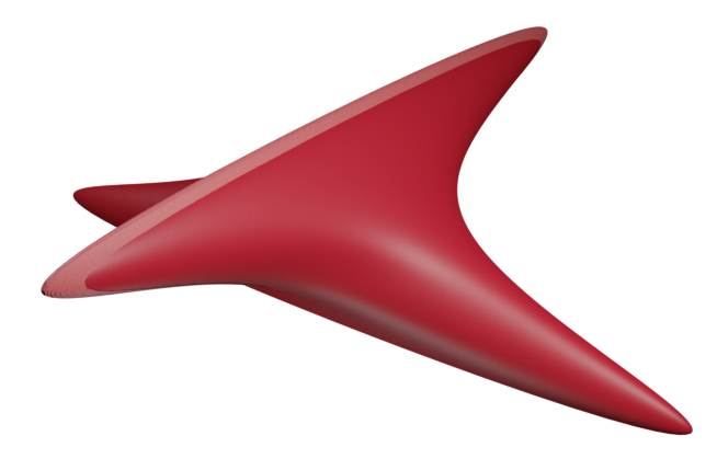
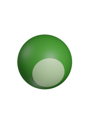
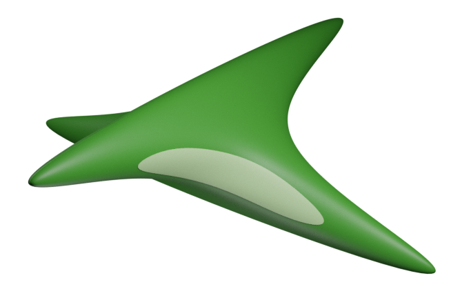
We assume that the total energy flux through the surface is constant, independent of the distance traveled. (Energy is transported by the light rays along geodesics, but not created or destroyed along the way.) This relates directly to the area density of geodesic spheres. That is, for any we have
where is the standard area form on the unit sphere in the tangent space, and is the pullback of the area form on to . We may express in terms of ; the resulting scale factor is the area density . Thus, the quantity is constant in for every solid angle . Assuming continuity and taking the limit over shrinking solid angles promotes this to a pointwise invariant: is independent of . Thus, is inversely proportional to , and
| (5.7) |
Remark 5.8.
The intensity experienced at from the direction is then just . A further correction to can occur when we add fog. Here the intensity drops off due both to (1) divergence/convergence of geodesics, and (2) distance traveled through the medium. A physically correct model for scattering from an isotropic source is already complex in euclidean space. However, as the primary goal of modeling fog is to provide useful depth cues (and hide sins), we treat these sources of loss as if they were independent, and use
when distance-dependent attenuation (fog) is desired. ∎
Equation (5.7) reduces the calculation of lighting intensity directly to the area density . In the next section, we calculate this area density by following infinitesimal patches of area along the geodesic flow.
5.7.1. Area density under the geodesic flow
Fix to be the location of a light source, and let be the exponential map. For fixed , define , so is a map of the unit tangent sphere at , into , formed by flowing along geodesics from for distance . Note that the image is not the sphere of radius about when is greater than the injectivity radius of . Recalling the notation above is defined as , for a solid angle . We denote the entire image as . Let be the standard area form on , and let be the area form on . Recall that the area density is the proportionality factor of the pullback to . We may compute this given any choice two non-collinear vectors in as
The area forms and measure the areas in of infinitesimal parallelograms in and respectively, and so may be evaluated in the algebra of bivectors on , where the area spanned by is given by
Thus, we have
| (5.9) |
Note that the numerator is the Jacobian derterminant of . As computing area elements requires nothing more than some evaluations of the metric, this reduces the calculation of area density to the computation of the differential .
Recall that , where is the exponential map. We see that for all and . To lighten notation, for the rest of this paragraph we identify with for every . Given in and in of unit length, this allows an explicit computation of in terms of the exponential map, as follows. Let be the unit vector in making angle with in the plane spanned by . Note that so we may calculate as
For each fixed , the map is a unit speed geodesic in , and the derivative is a vector field along this geodesic. Computed as above, we see this is a particularly nice vector field: it is the derivative of the geodesic flow along a one-parameter family of geodesics. Such vector fields are called Jacobi fields.
Given a smooth one-parameter family of geodesics through , the Jacobi field associated to is given by . In general, one may bypass explicit computations involving , and compute such Jacobi fields by solving a differential equation. The Jacobi field along with initial conditions satisfies the so called Jacobi equation,
| (5.10) |
where is the Riemann curvature tensor. For us then, and are the Jacobi fields along corresponding to the variations and respectively, so
| (5.11) |
In the isotropic geometries and product geometries, Equation (5.10) reduces to a second-order differential equation with constant coefficients. In any geometry where one may solve Equation (5.10), the area density is given as follows. For fixed , choose two vectors with and solve the Jacobi equation for the two Jacobi fields . Then using Equations 5.9 and 5.11, we have
| (5.12) |
In the harder geometries, solving Equation (5.10) is more challenging. Following Section 3.2.1, one could use Grayson’s method to replace Equation (5.10) with a system of differential equations on . This is not what we do though. Since we already computed the exponential map (using Grayson’s method) we directly compute its differential .
Let be the standard spherical coordinates on , with the angle measured from the north pole. Let have coordinates . Note that as the coordinate vector fields are orthogonal to , we may use them to make a uniform choice , and compute
In practice, due to the rotational symmetry in Nil and about a single axis, it is more convenient to perform this computation in cylindrical coordinates, with and . For ease of notation, we retain from spherical coordinates to denote the distance traveled along the geodesic.
| (5.13) |
5.8. Lighting in quotient manifolds
The basic algorithms for lighting remain virtually unchanged in a quotient manifold. Phong lighting is still computed in the tangent space, and the only modification to the computation of shadows and reflections is to modify the ray-march as in Section 4. There is only one major change worthy of discussion: the calculation of direction vectors pointing from the surface to a given light. This is even more necessarily multi-valued here, as light may travel in loops around the manifold before impacting the surface. Indeed, a light in is the same as a -equivariant collection of lights in . When required for disambiguation, we will denote the set of lighting pairs in a space as . For the location of a light in , thought of as the fundamental domain for , the lighting pairs can be written in terms of the lighting pairs of Section 5.6:
Note that there is no sense in which is some sort of “-translate” of : the individual sets in this union may not even have the same cardinality. This occurs for instance in Nil, where even if the distance from to is less than the injectivity radius, there may be a with arbitrarily many geodesics from to . As lighting is calculated individually for each direction and summed weighted by intensity, it is in general impossible to compute this exactly for any manifold with infinite fundamental group. Instead, for all but spherical manifolds and orbifolds, we must approximate the lighting by computing only for those paths with significant intensity.
Light intensity is inversely correlated with geodesic length of a segment from to in geometries with non-positive sectional curvature, and in all geometries if we use fog. Thus we get a reasonable approximation to the correct image by restricting to directions corresponding to ‘sufficiently short’ geodesics. Considering only the directions from lights within (that is, when ) is not enough, as some nearby translates still contribute significantly. Compare Figure 5.9a with Figure 5.9c. The latter shows the correct lighting in the quotient of the three-sphere by the binary tetrahedral group. The former shows lighting using one of the 24 light sources. An improved approximation is to use the ‘nearest neighbors’ idea from Section 4.2.2, and consider only tangent directions at which reach the light at , or its translates through the faces of . See Figure 5.9b.
This is even an issue in euclidean manifolds. Note that there is a discontinuity in the lighting of the red balls in Figure 4.5c. The left and right hemispheres are lit by different collections of lights, since they sit in different fundamental domains.
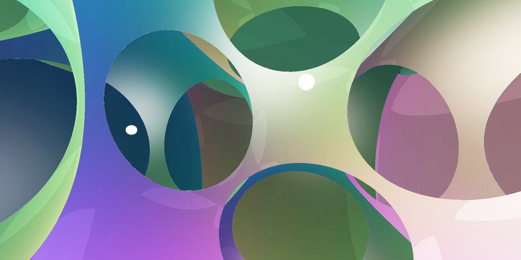
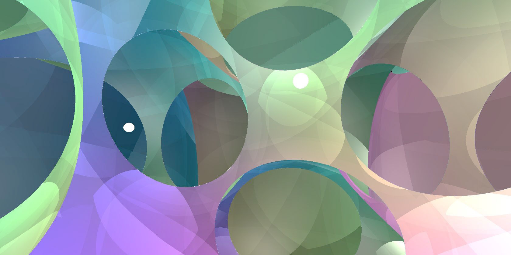
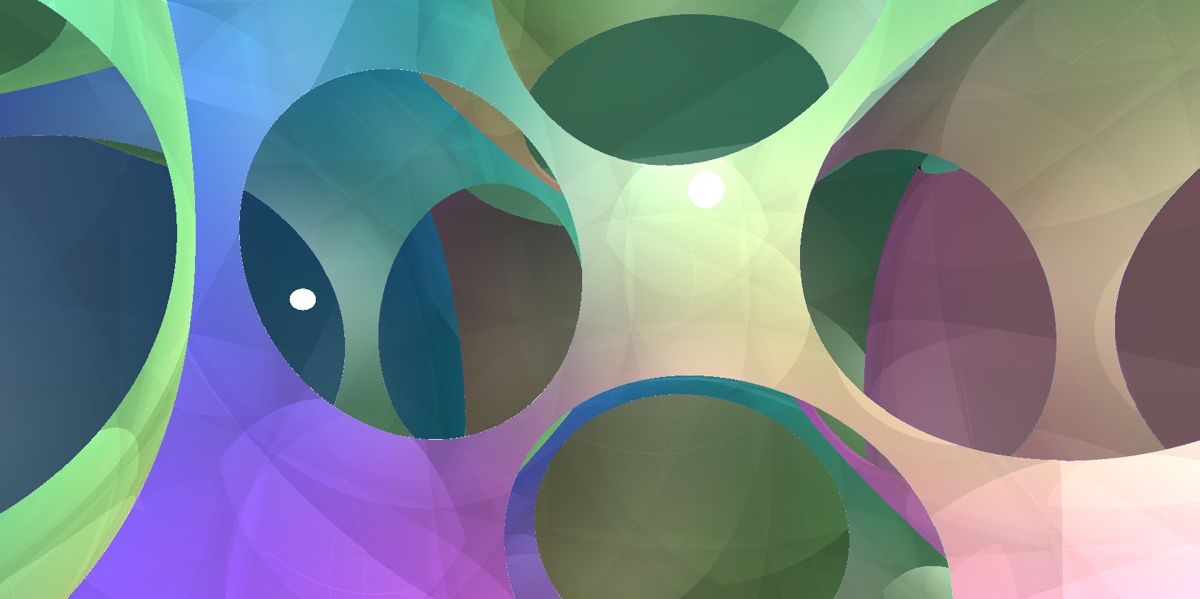
In geometries with positive sectional curvatures, light can converge again over long distances, meaning that there are certain directions where even long geodesics make significant contributions to the overall sum unless we use fog. Which translates of the lights to include in a calculation then depends on both the geometry and the scene. So far, we have only a heuristic understanding of how to choose translates appropriately, based on the light intensity function for each geometry.
5.9. Cheating
Accurate lighting and shading is a complex problem, requiring many calculations, and many ray-marches per pixel to perform correctly. As we strive to produce as accurate a simulation as possible, we have worked to implement lighting, shadows, reflections, and fog as described above. However, insistence on complete “physical” accuracy is not ideal for all applications. Sometimes lighting is best thought of as a means for euclidean humans to better perceive the geometry, rather than as a feature of the geometry in itself. This is analogous to astrophysical simulations, where it is more important to correctly render the size and position of celestial bodies, rather than to faithfully reproduce the brightness of the sun. In these situations it is often desirable to purposely employ nonphysical lighting to improve speed and/or visibility.
We find that the most often useful change to make is in the relationship of light intensity with distance. There are two main problems that we can solve here.
-
•
First, correct lighting may give intensities of vastly different magnitudes for different parts of the same scene. This means that parts of the scene will be too dark for our eyes to see any structure. Alternatively, we can increase the brightness of the lights, but then other parts of the scene will be oversaturated.
-
•
Second, and more subtly, we use variation in brightness as a depth cue, telling us how far away an object is from a light source.
Figure 5.10a shows a scene in lit by a single light. Here, exponential falloff in intensity with distance leaves everything other than the central cell shrouded in darkness. We see similar behavior in Figure 5.12c, when looking in a hyperbolic direction in . When we look in a euclidean direction in Figure 5.12a, we do see neighboring cells, giving the impression that cells are closer in that direction than in the hyperbolic directions. In Figure 5.11a, the correct lighting calculations in give an approximately even brightness over the whole image, even though only the ball at the center is particularly close to the viewer. The space works like a fiber-optic cable – on average, the intensity of the light does not decrease with distance as we move along the cable.
Instead of the correct lighting intensity , we may cheat, and use an artificial slowly decreasing intensity (say, inversely proportional to geodesic length). This provides more helpful depth cues and may also be less expensive to compute. See Figures 5.10b, 5.11b, 5.12b, and 5.12d. As a side benefit, this also allows one to see distant reaches of a negatively curved space with only a few light sources. This also reduces computational cost.
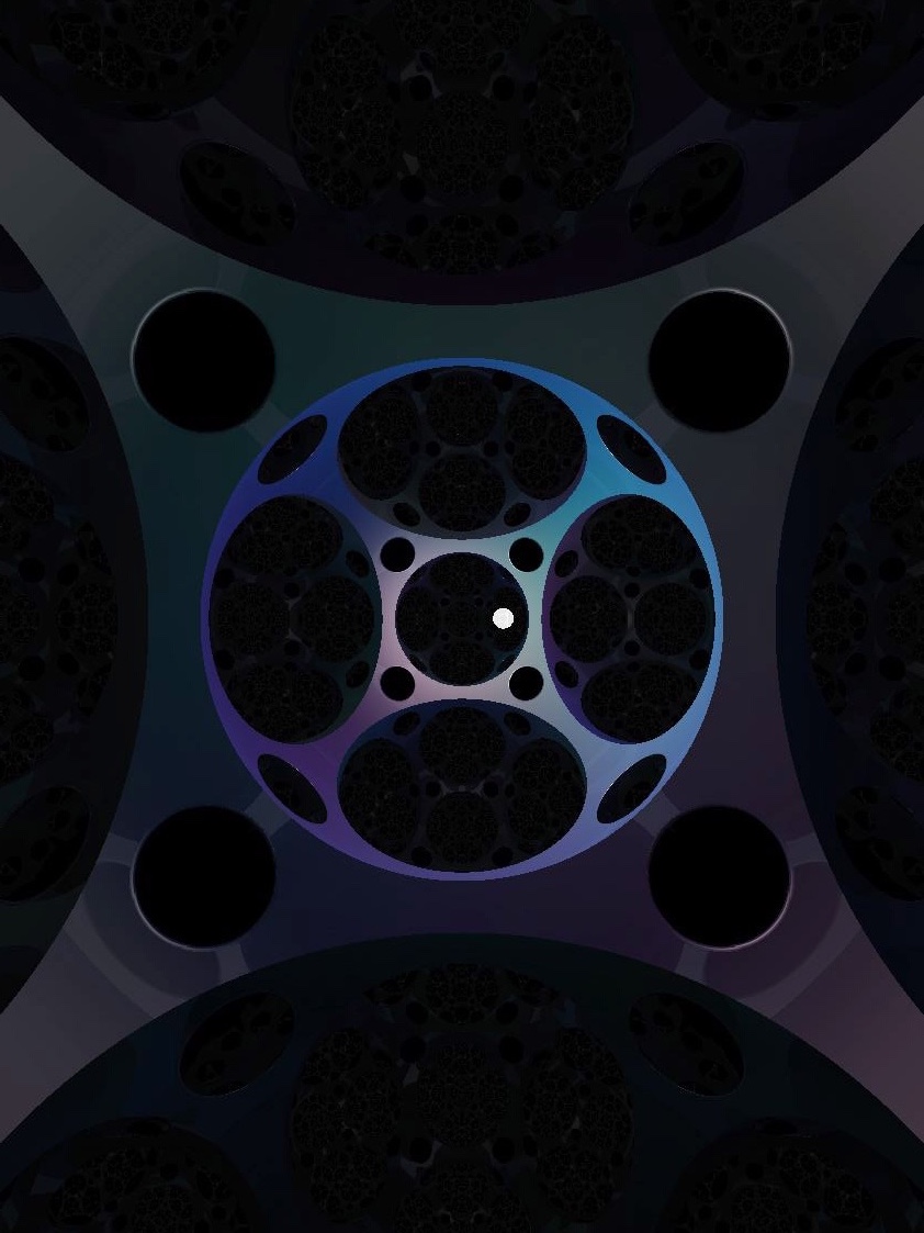
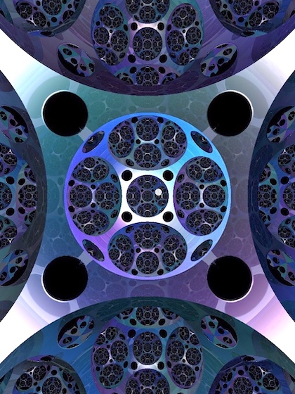
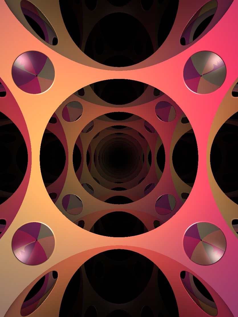
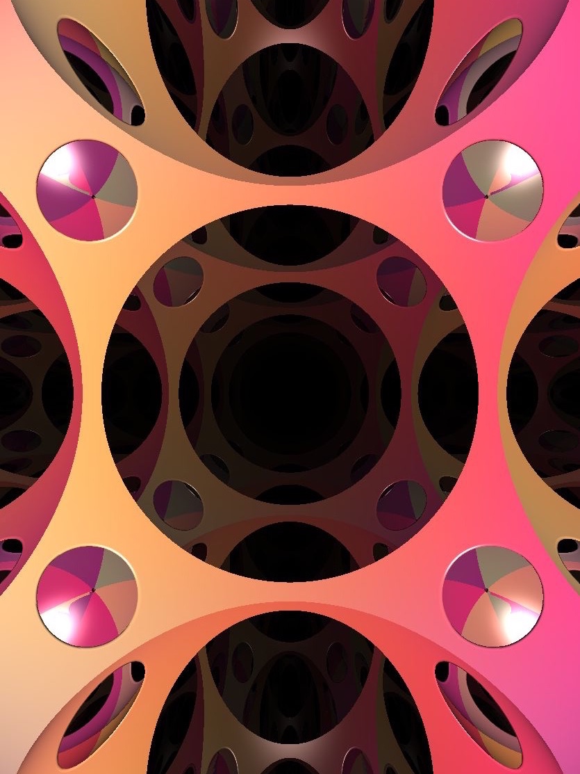
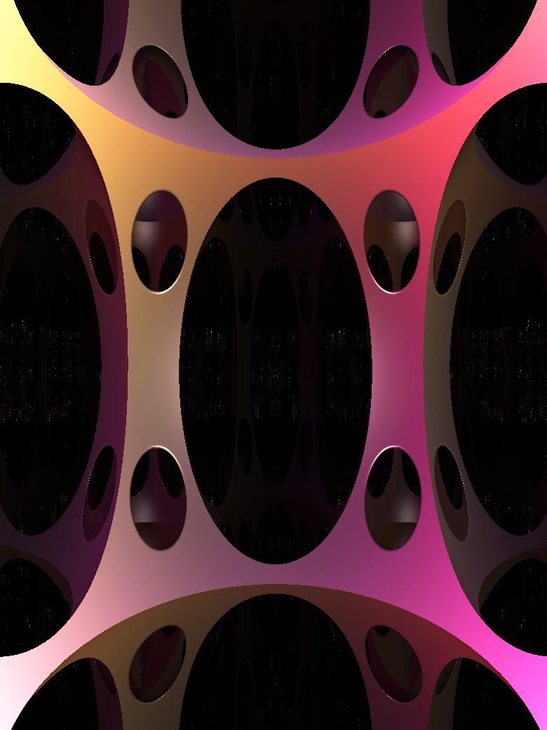
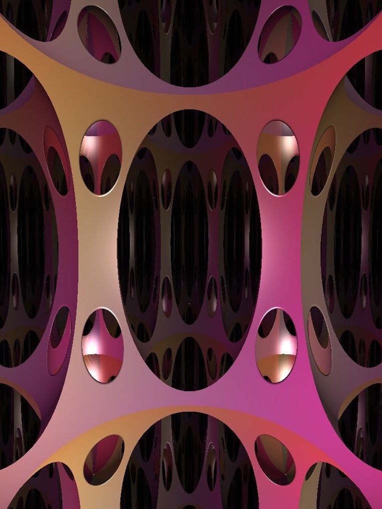
When it comes to improving speed, we may pare down the lighting pipeline to focus on giving accurate depth cues. This means preserving Phong lighting and fog, while perhaps ignoring shadows, or not using reflective materials. Another efficiency gain which does not affect the intelligibility of the scene is to consider only the direction to the light along the shortest geodesic, instead of the set of all directions. Even when attempting accurate rendering, it is often acceptable to ignore lighting along all but the shortest few geodesics. This is the case when using fog, or when the intensity fall-off makes the contribution to the weighted average along longer geodesics negligible.
However, using fewer geodesics can introduce very visible errors. In a quotient manifold, as we saw in Figures 5.9 and 4.5c we may lose shadows, or introduce discontinuities in the perceived light intensity. In some geometries, using fewer geodesics can in fact remove discontinuities in lighting intensity that should be there.
We usually indicate the position of a light with a ball in the scene centered on the light source, making sure that the shadow calculation for that light ignores the ball. To remove visual complication, we sometimes choose to not render these balls. Along these lines, in some situations we may not actually care, or may not be able to efficiently calculate, the lighting pairs . Instead, we may simply choose for each light source a continuously varying direction field . We give up on correctness, but still provide a seamless view and give visual cues. Figure 5.13 compares different choices of illumination in Nil.
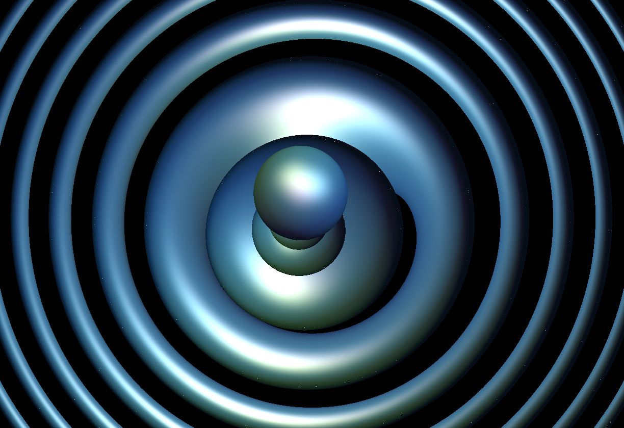
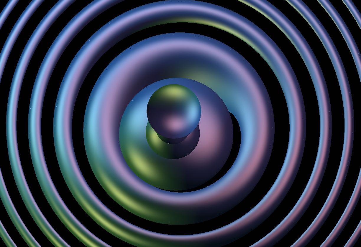
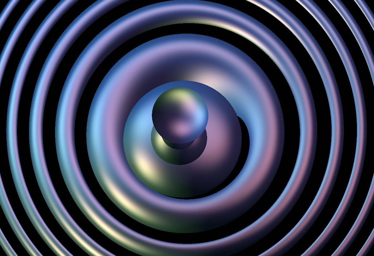
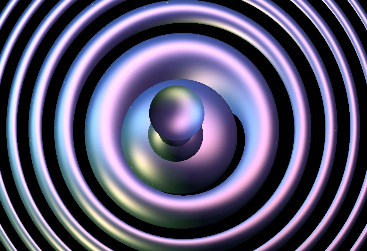
6. Implementing specific geometries
In previous sections we have described our strategies in a more-or-less geometry independent manner. Here we begin to give specific details for each of the eight Thurston geometries. To summarize the previous sections, for each geometry, we require the following:
-
(1)
A model for with action of the group of isometries . That is, we must now be explicit about how points and isometries are described by vectors or matrices of floating point numbers.
-
(2)
Arc length parametrized geodesics in the model. That is, a way to flow a position and tangent vector at that position along the ray by a given distance, as described in Section 3.2.
-
(3)
Signed distance functions in the model.
In order to render a quotient manifold with this geometry, we also need:
-
(4)
A fundamental domain with face pairings .
For the Phong reflection model of lighting, we need:
-
(5)
For a point (where a ray hits a surface) and the location of a light source , the set of lighting pairs of geodesics joining to and vice versa. See Section 5.6.
To allow the user to move, we also require
-
(6)
Parallel transport along geodesic arcs. (Used to translate movement of the user’s frame in into isometries of .)
For each of the eight Thurston geometries, we list some of these ingredients in Table 1. All of our models are subsets of .
We give further details in the following sections. We consider the isotropic geometries in Section 7, the product geometries in Section 8, and Nil, , and Sol in Sections 9, 10, and 11 respectively. A general reference for Thurston’s geometries is [Sco83].
| Geometry | Model (Set, Metric, Origin ) | Geodesic from in direction | Isometries | Example Lattices |
|---|---|---|---|---|
| , , , | ||||
| , , | The eight element quaternion group. | |||
| , , | The isometry group of Seifert-Weber space. | |||
| , , | where and | where is a discrete subgroup of | ||
| , , | where and | where is a discrete subgroup of | ||
| Nil | See Section 9.2, | See Section 9.3 | with , parabolic | |
| , See Section 10.1, | See Sections 10.2 and 10.3 | “Lift” of with compact genus surface | ||
| Sol | , | See Section 11.2 | with , hyperbolic |
7. Isotropic geometries
In this section we give implementation details for , and . For further background, we refer the reader to [BH99, Chapter I.2]. See also [Wee02]. Many details for these three geometries are very similar; for the convenience of the reader, we list these explicitly. In particular, we give distance functions for some simple shapes in standard positions. They can be conjugated by isometries to give signed distance functions for these shapes in general position. We also reference the possible discrete groups (or equivalently, manifolds) for each geometry.
7.1. Euclidean space
We represent as the affine subspace of . The origin is the point . The distance between two points and is given by
Using a hyperplane to represent is standard in computer graphics because the isometry group of acts on by linear transformations of preserving . We identify the tangent space at a point with the linear subspace of . The arc length parametrized geodesic starting at and directed by the unit vector is simply . In Table 2, we list signed distance functions for some simple objects in .
| Object | Signed distance function |
|---|---|
| Ball of radius centered at the origin | |
| Solid cylinder of radius with axis the geodesic | |
| Half-space |
From a group theoretic point of view, the co-compact discrete subgroups of have been classified. These are the crystallographic groups [BBC72]. Note that every finite volume euclidean three-manifold is finitely covered by the three-torus. In Figure 7.1, we show the in-space view for various scenes within the regular three-torus, rendered with a multicolor collection of five lights. In these images, light intensity falls off proportional to the inverse square of distance. An object receives lighting from the cell it is contained in and that cell’s nearest neighbors.
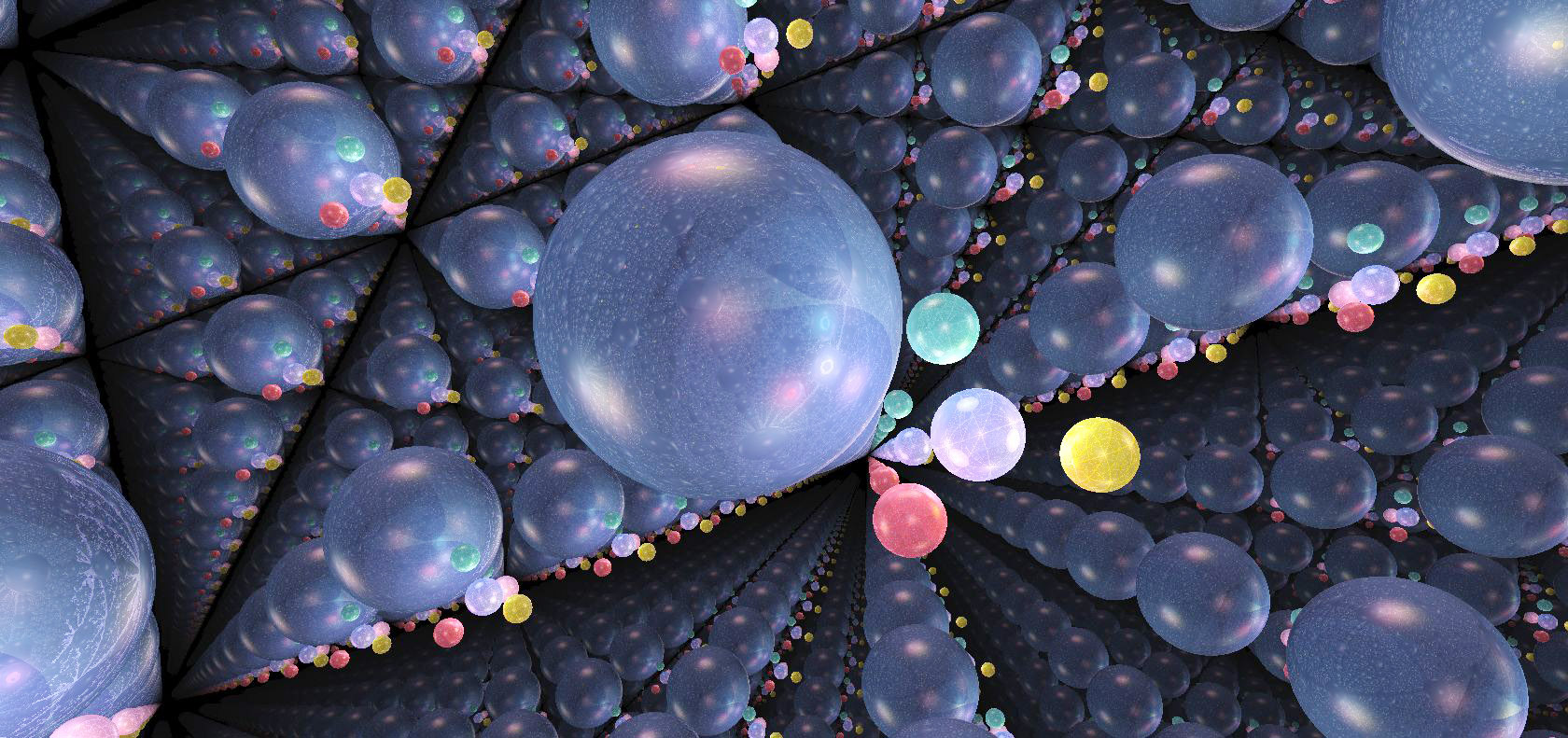
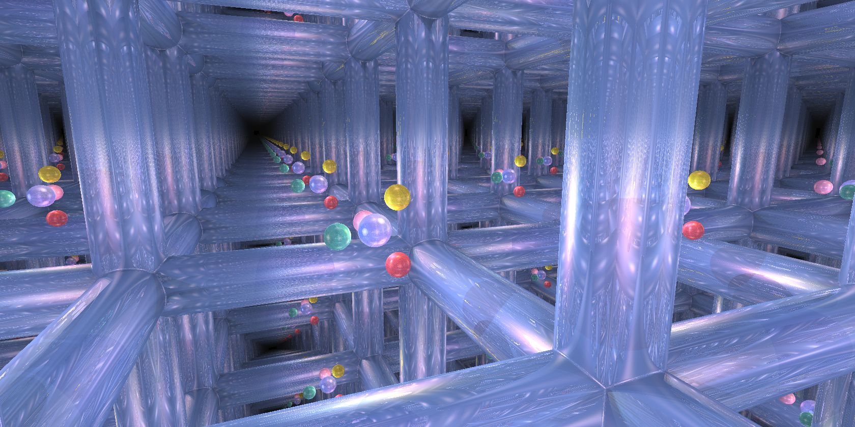
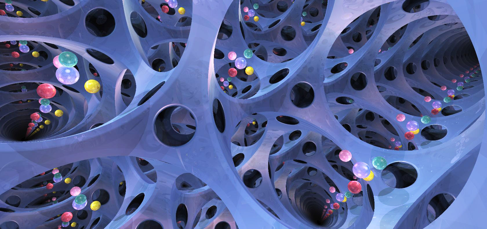
7.2. The three-sphere
We endow with the standard scalar product. That is, given and we let
We view as the set of points satisfying the identity . We choose for the origin the point . The distance between two points and is characterized by
The isometry group of acts on by linear transformations of preserving the scalar product and so . We identify the tangent space at a point in with the linear subspace
of . The arc length parametrized geodesic starting at and directed by the unit vector is given by . In Table 3, we list a few examples of signed distance functions in .
| Object | Signed distance function |
|---|---|
| Ball of radius centered at the origin | |
| Solid cylinder of radius whose axis is the geodesic | |
| Half-space |
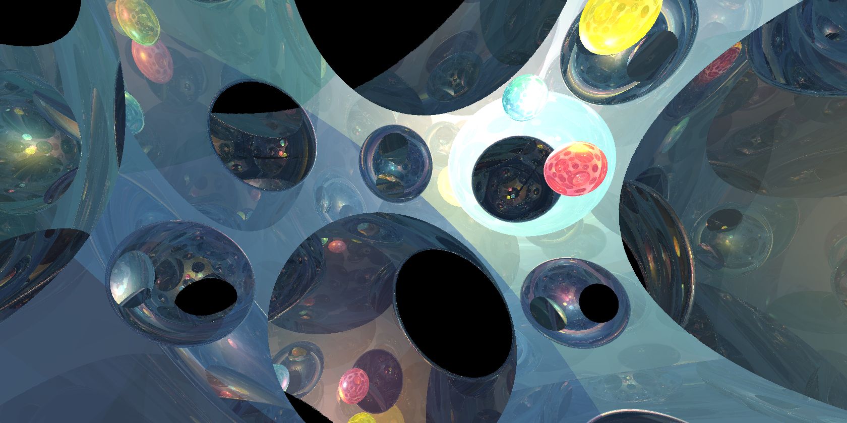
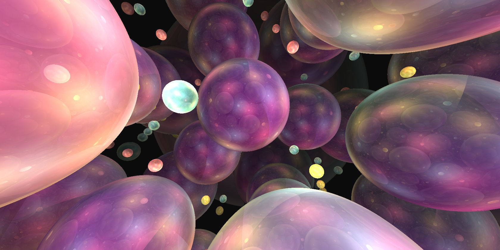
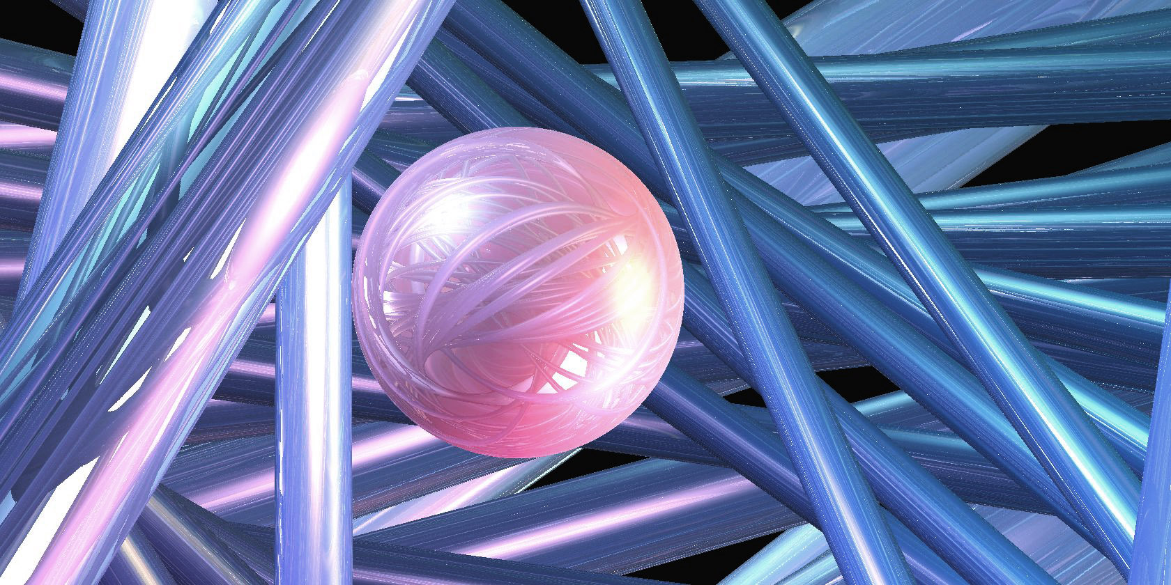
The finite subgroups of are classified in [Sco83, page 449]. In Figure 7.2 we show the in-space view for various scenes in spherical geometry. Figure 7.2a shows the quotient of by the quaternion group of order eight, . Edges of the fundamental domain are shown as in Figure 2.1c, but with balls also deleted from the edge midpoints. Figure 7.2b shows a single mirrored ball and three light sources in Poincaré dodecahedral space. Figure 7.2c shows the lifts of some randomly chosen fibers of the unit tangent bundle over (the Hopf fibration), and their reflected images in a ball. These are the fibers of the Seifert fiber space structure on spherical three-manifolds.
7.3. Hyperbolic space
We endow with a lorentzian inner product: for every and we let
We use the hyperboloid model of . This consists of the set of points in such that and . We choose for the origin the point . The distance between two points and is given by
The isometry group of acts on by linear transformations of preserving the lorentzian product and so . We identify the tangent space at a point in with the linear subspace
of . The arc length parametrized geodesic starting at and directed by the unit vector is given by . In Table 4, we list a few examples of signed distance functions in .
| Object | Signed distance function |
|---|---|
| Ball of radius centered at the origin | |
| Solid cylinder of radius whose axis is the geodesic | |
| Half-space |
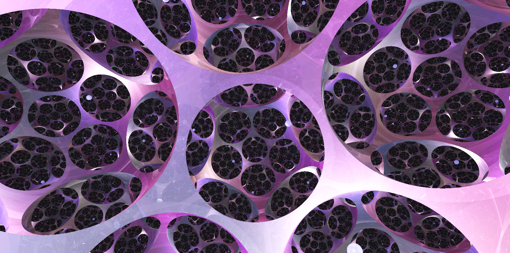
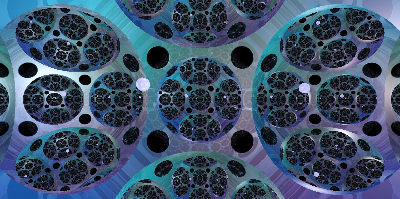
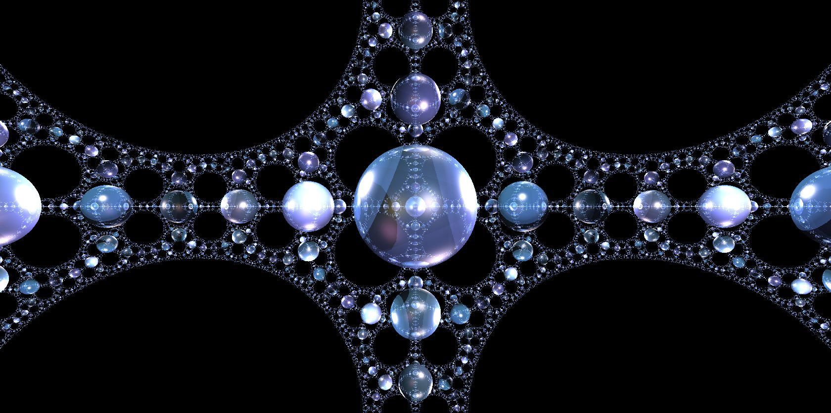
Of the eight Thurston geometries, the classification of hyperbolic manifolds (and orbifolds) is the least well understood. The software SnapPy [CDGW] lists numerous censuses of finite volume hyperbolic manifolds. In Figure 7.3 we show the in-space view for various scenes in hyperbolic geometry. Figure 7.3a shows Seifert-Weber dodecahedral space, with a fundamental domain drawn in a style similar to Figure 2.1b. Figure 7.3b shows the finite volume cusped orbifold formed from an ideal cube (with dihedral angles of ), by identifying opposite faces with a turn. The underlying manifold is (see Figure 7.2a) minus the vertices of the cube, with cone angles of at each edge of the cube. Figure 7.3c shows a sphere in an infinite volume hyperbolic orbifold formed from a hyperideal cube [NS17, Section 6.1] (with dihedral angles of ), by identifying opposite faces by translation. The limit set is the visible as the limiting pattern of spheres. The underlying manifold is the three-torus, minus a ball around the vertex, with cone angles of at each edge of the cube.
7.4. Facing and parallel transport
By definition, for each isotropic geometry , the isometry group acts transitively on the unit tangent bundle of . It follows that the position and facing of an observer can be captured by a single isometry, as explained in Section 3.3. Nevertheless, to keep the code as geometry-independent as possible, we encode our position and facing by a pair where is an isometry of and is the identity.
As we noted in Section 3.4, given any geodesic starting at , there is a one-parameter orientation preserving subgroup such that . Thus the corresponding parallel transport operator is simply . This considerably simplifies the computations: if an observer starts at and follows for time , then the observer’s new position and facing are .
7.5. Lighting
The calculation of lighting intensity for the isotropic geometries is straightforward in comparison to the other geometries. Recall from Equation (5.7) that the intensity is inversely proportional to the area density of geodesic spheres.Equation (5.12) relates area density directly to Jacobi fields along the geodesic in the direction . Here, all sectional curvatures are equal, so all Jacobi fields are parallel along geodesics, and have magnitude controlled by the curvature. Precisely, if and is the parallel transport of along the geodesic with initial tangent , the corresponding Jacobi fields are below.
Choosing a pair of orthonormal initial conditions and using Equation (5.12) gives the area densities:
Thus light intensity falls off quadratically with distance in euclidean space, and exponentially in hyperbolic space. In the three-sphere, the intensity initially decreases with distance, but beyond a distance of , it increases as all light rays begin to converge towards the antipode. Figure 7.4 shows graphs of the intensity function on the tangent space . A point at distance from the origin in the direction is colored by the value of . Dark blues represent low intensity, and yellows represent high intensity. Each plot depicts a ball of radius ten. Note that for the three-sphere diverges to infinity along spheres with as, under the exponential map, all light refocuses at the light source or its antipode.
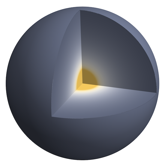
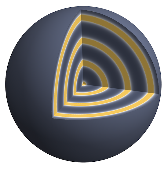
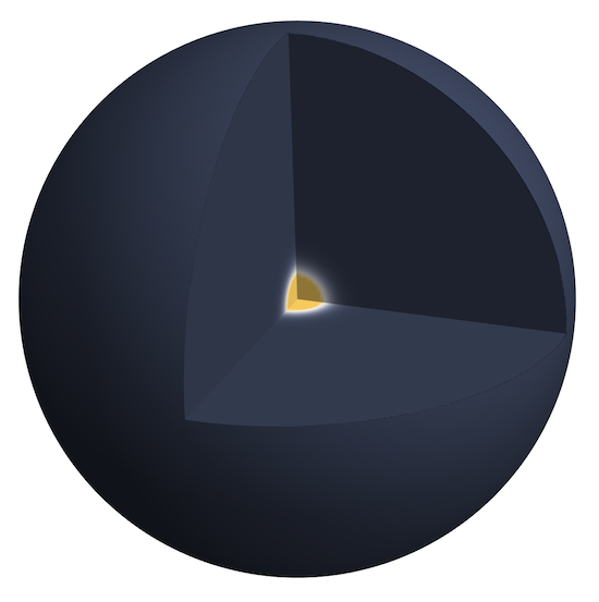
We now turn to the calculation of the lighting pairs : the set of pairs of initial tangent vectors to geodesics joining to , and their corresponding lengths . In all three isotropic geometries, this can be calculated using linear algebra in the ambient space where the models reside.
In euclidean space, geodesics are unique. Given , the required direction vector is simply .
In spherical geometry, given non-antipodal, let be the acute angle between them. The shortest geodesic from to has length and direction , appropriately rescaled. The second geodesic points in the opposite direction, with length .
Remark 7.1.
Strictly speaking, we should also include copies of the above pairs with distances modified by adding for all integers . However, if either the light source or the scene is opaque then these copies are never relevant. ∎
In practice, we don’t worry about and being antipodal: in a generic render, no pixels will involve such a situation. Moreover, if we are exceedingly unlucky and do have such a pixel, GPU code does not crash when asked to, for example, divide by zero. It just gives up and moves on to the next pixel. However, one could special-case this situation: for a pair of antipodal points , all directions from reach after traveling a distance , and so we find that the set is uncountable. As the lighting intensity diverges to infinity as one approaches such a configuration, the pixels should be colored as bright as possible.
In hyperbolic geometry we proceed analogously to the three sphere, except that we use the Minkowski inner product. Given , let be the hyperbolic distance between them. Geodesics between pairs of points in are unique, so is again a singleton:
8. Product geometries
Before describing the product geometries, we quickly introduce model spaces for and .
8.1. Models of and
Our models for and are the same as those for and , with one fewer dimension:
-
•
We view as the set of points in such that , where is the canonical scalar product in .
-
•
We represent as the set of points in such that , where is the lorentzian product in .
8.2. Product geometries
Our model for (respectively ) is the subset of , where (respectively ). We choose for the origin the point . The space is equipped with the product distance. That is, given two points and in we have
The tangent space at a point naturally splits as . Given a vector we denote by and its components in and respectively. The arc length parametrized geodesic starting at in the direction of the unit vector is given by
where is the geodesic ray in starting at with initial tangent vector .
Next, we consider signed distance functions. As usual, the distance formula gives us the signed distance function for a ball. We call an object vertical if it is the pre-image of a non empty subset by the projection . The signed distance function for such an object is given by
We define horizontal objects, and obtain their signed distance functions in an analogous way. Tables 5 and 6 list a few examples of such signed distance functions.
| Object | Signed distance function |
|---|---|
| Solid cylinder of radius with axis the geodesic | |
| Half-space | |
| Half-space |
| Object | Signed distance function |
|---|---|
| Cylinder of radius whose axis is the geodesic | |
| Half-space | |
| Half-space |
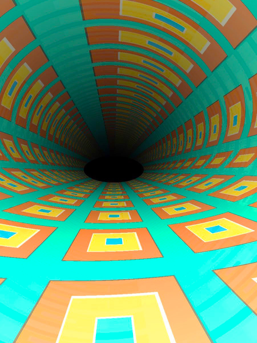
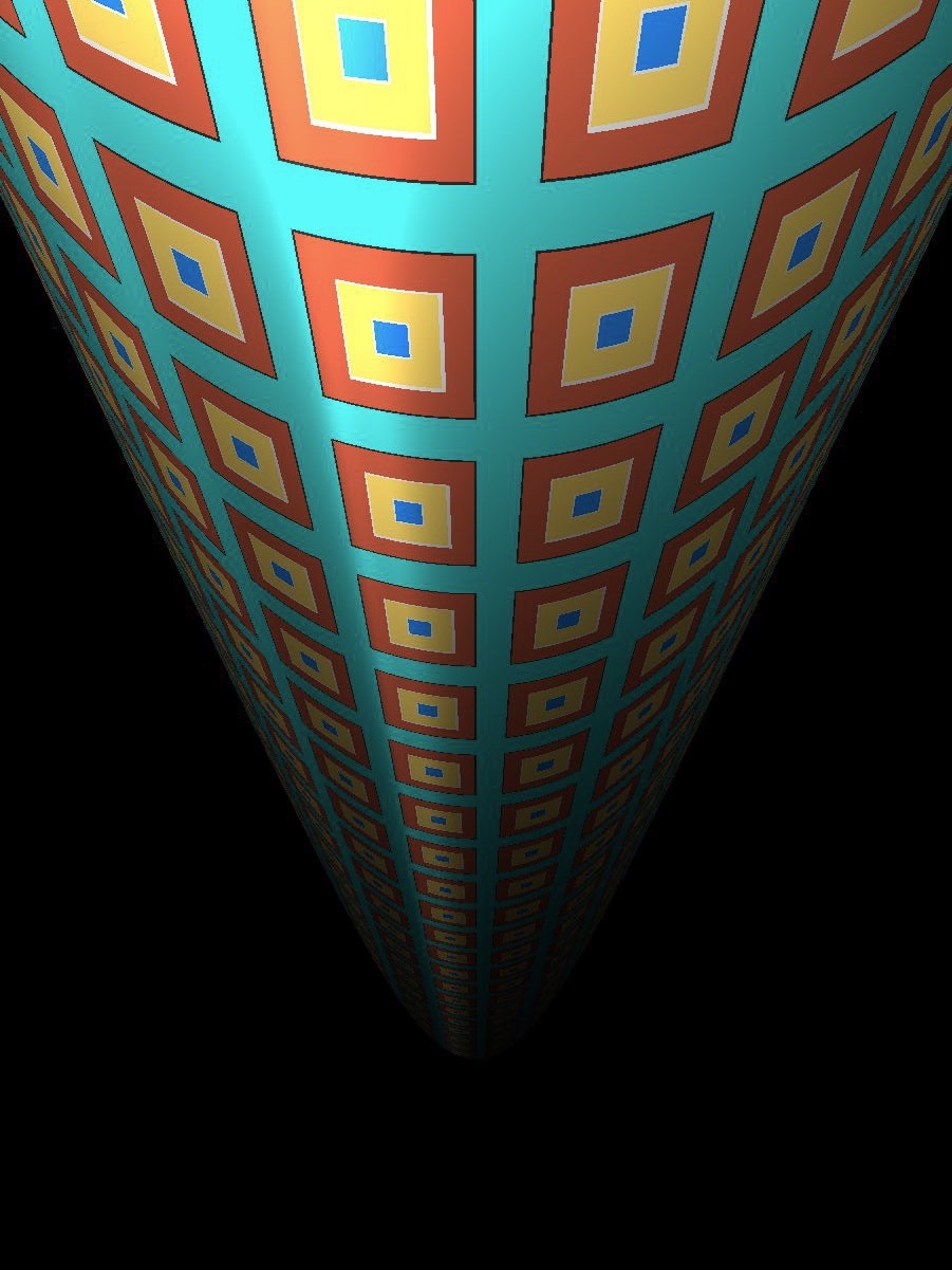
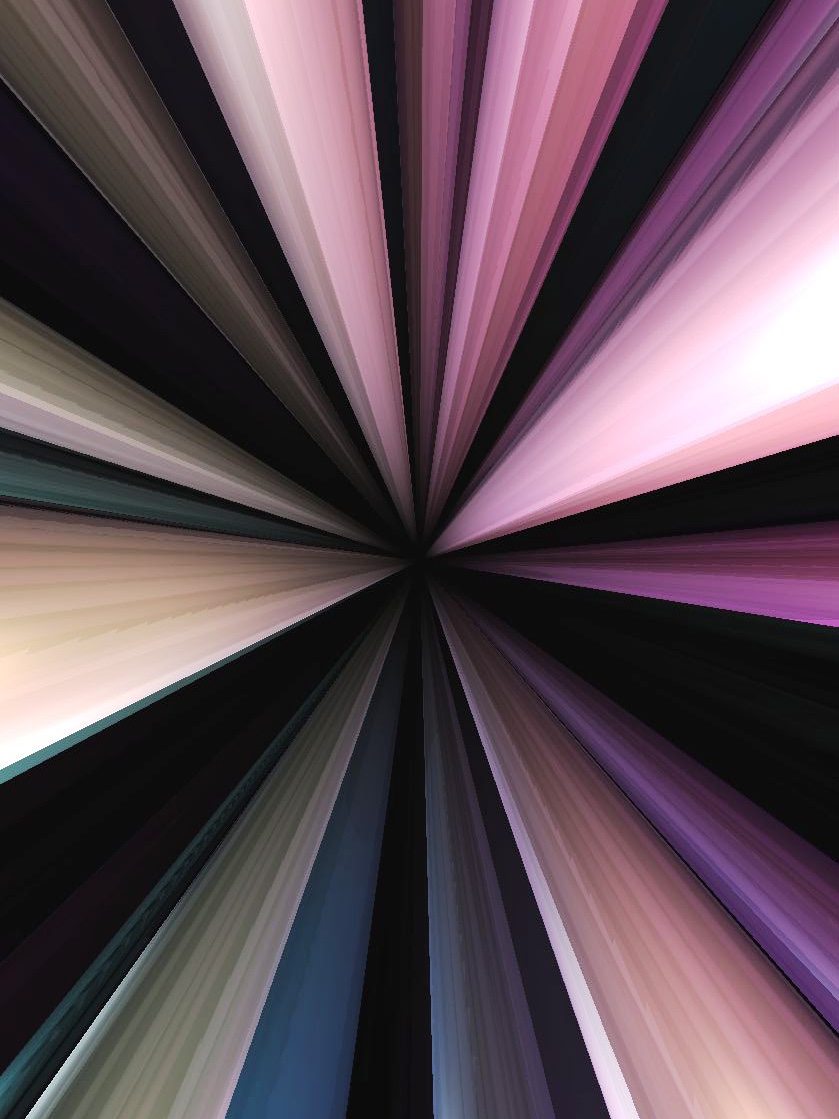
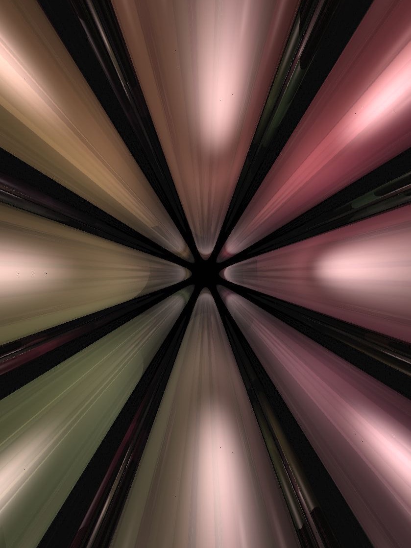
Figure 8.1 shows vertical half-spaces in the product geometries. Figure 8.2 shows solid cylinders around some fibers in the direction for the product geometries. In Figure 8.2a we place solid cylinders around fibers above the vertices of an icosahedron in the factor. In Figure 8.2b the solid cylinders are around fibers in the direction.
8.3. Facing and parallel transport
Unlike for the isotropic geometries, the position and facing of the observer cannot be encoded with a single element of . Hence we represent it by a pair as explained in Section 3.3. Nevertheless, if is a geodesic starting at the observer’s position , there is still a one-parameter orientation preserving subgroup such that . Thus after moving along for a time , the observer’s new position and facing is .
8.4. Lighting
We again use Equation (5.12) to reduce the calculation of area density (and hence light intensity) to the computation of Jacobi fields. Let , choose a unit vector and let be the geodesic starting at with initial tangent . General Jacobi fields need not be parallel along , and may rotate in the presence of a gradient in sectional curvature. When is such that the curvature of the plane spanned by is a local extremum however, then the Jacobi field with initial condition is parallel along . In this case, its magnitude is determined by , as in Section 7.5.
If is vertical (that is, ), then is symmetric under rotation about , and all planes containing have zero sectional curvature. If has parallel translate along , then the corresponding Jacobi field is . Choosing two such orthonormal conditions, Equation (5.12) implies that .
In general, suppose that makes an angle of with the vertical. Then is contained in a unique vertical plane , which again has zero sectional curvature. This realizes one of the extremal curvatures at (it is a maximum for and a minimum for ). Choosing extending to an orthonormal basis for , the Jacobi field with initial condition is as above.
The other extremal curvature is realized by the plane , orthogonal to and containing . Using the bilinearity of the Riemann curvature tensor, one can calculate this extremal curvature from the angle that makes with the vertical, and the curvature of the horizontal plane :
Let extend to an orthonormal basis for , and be its parallel translate along . The Jacobi field with initial condition is , where is either sine or hyperbolic sine as is greater or less than zero respectively. Combining these with Equation (5.12) gives the area density for each of the product geometries below.
| (8.1) |
Figure 8.3 shows the behavior of on a ball of radius ten in the tangent space at for the two product geometries. Figure 8.4 shows some effects of this behavior on the in-space view.
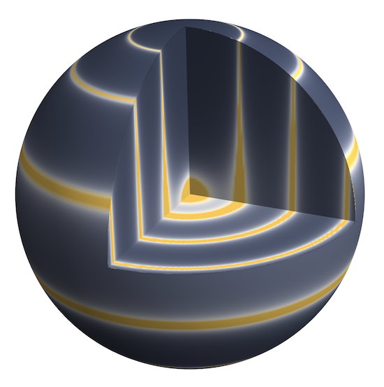
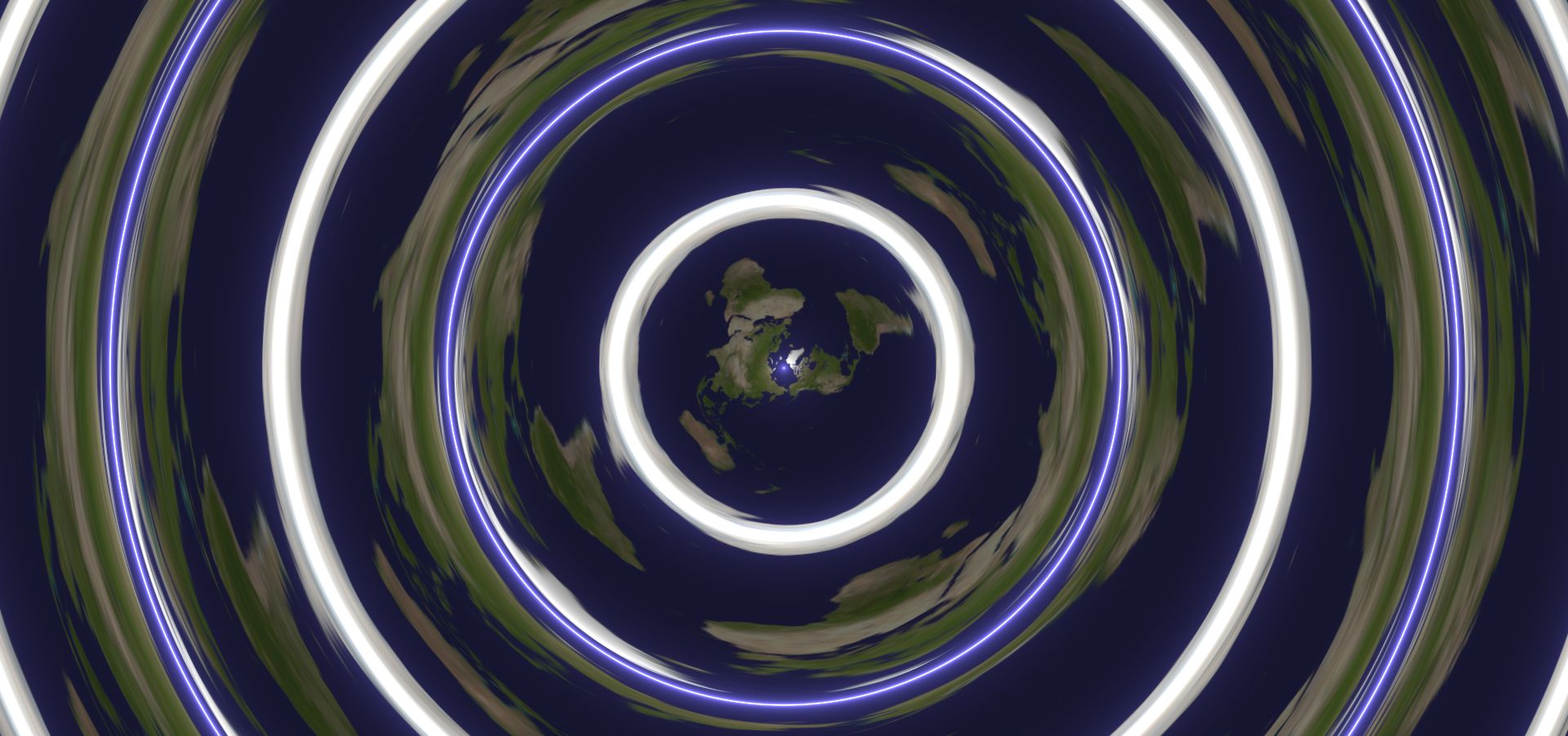
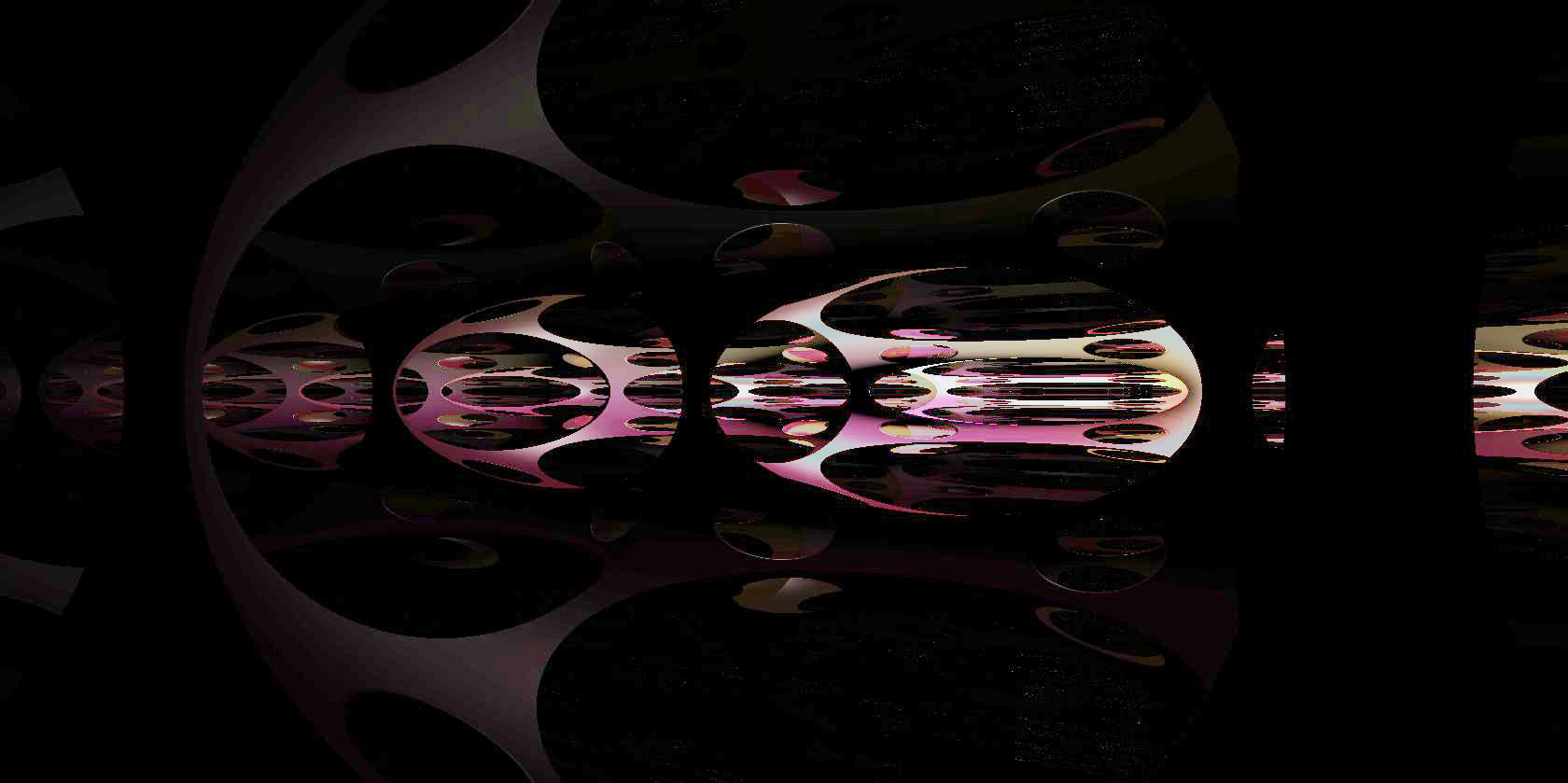
Finally, we must also compute the directions from a point to the light source at . To simplify the notation here, we will write each lighting pair of not as a pair , but as a vector of length in the direction . Let and let , be the distances between their projections into the respective factors of . Recall that the standard basis vector points along the direction. We compute the unit vector pointing along the shortest geodesic from to as in Section 7.5. The element of corresponding to the shortest geodesic is then . In geodesics are unique, so with this we are done:
In , there are three cases to deal with: first the generic case, second when lie on the same horizontal , and third when are antipodal. As for , in the implementation we don’t worry about the non-generic cases; the lighting intensity at such points is the limit of the lighting intensity for the generic case.
In the generic case, there are countably many geodesics between and . All of these geodesics lie on the cylinder formed by taking the product of the direction with the great circle containing and . For each natural number , there are two geodesics – one starting by traveling the ‘short way’ around the factor, followed by additional full turns, and the other the ‘long way’ followed by additional turns. All together, this gives the set of directions
If and are not antipodal, then we just set above. As in Remark 7.1, all but the shortest two are irrelevant if either the light source or the scene is opaque.
In the third case, where are antipodal in , there are uncountably many geodesics joining to . Their directions are a countable sequence of rings in the unit sphere in accumulating on the horizontal equatorial circle.
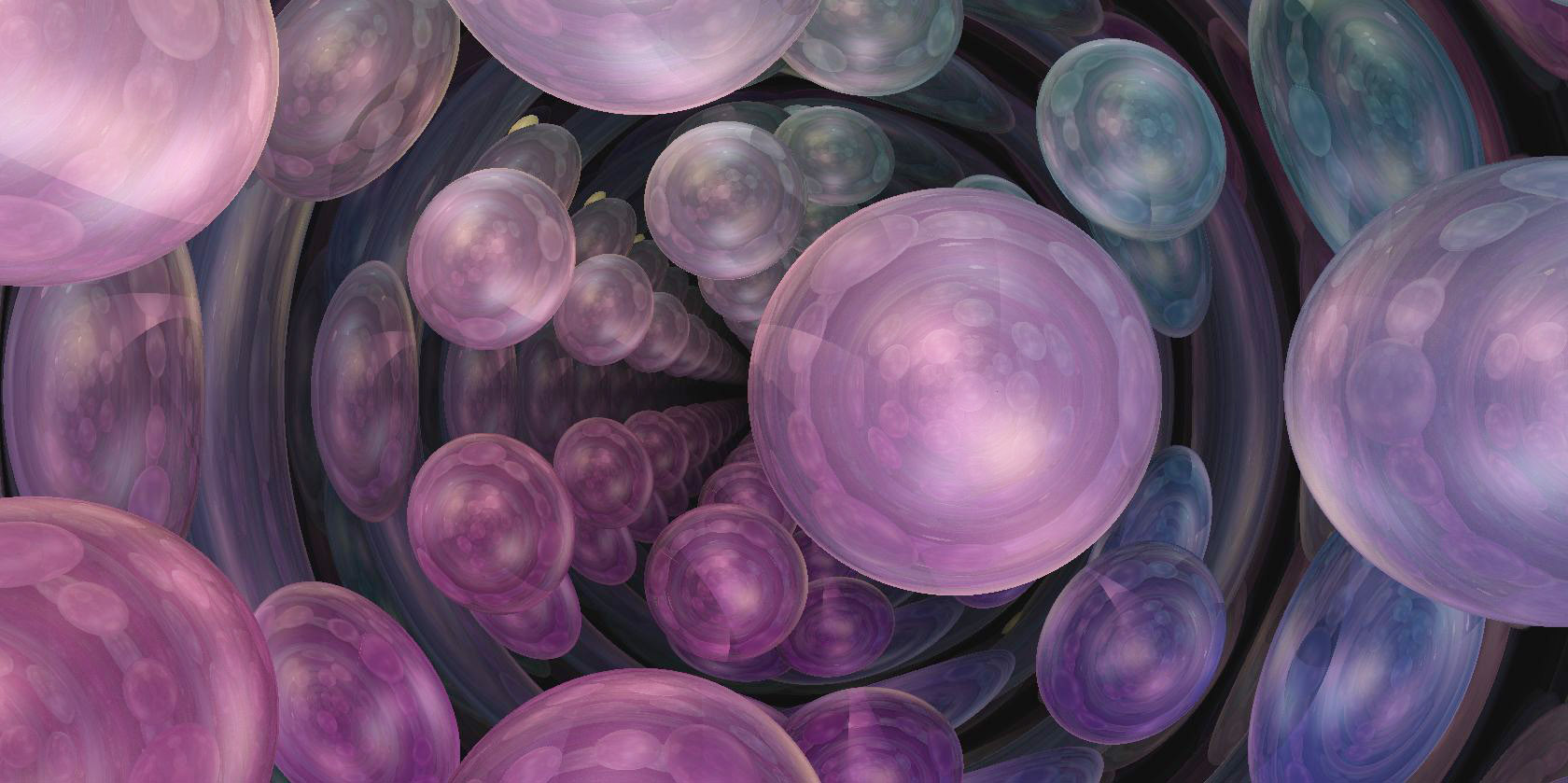
There are only seven manifolds with geometry. These are listed in [Sco83, page 457]. In Figure 8.5, we show the in-space view for various scenes in the Hopf manifold . Figures 8.5a and 8.5b show a collection of spheres spaced at the vertices of a regular dodecahedron. Figure 8.5c shows a slab , with holes cut out at the vertices of the dodecahedron.
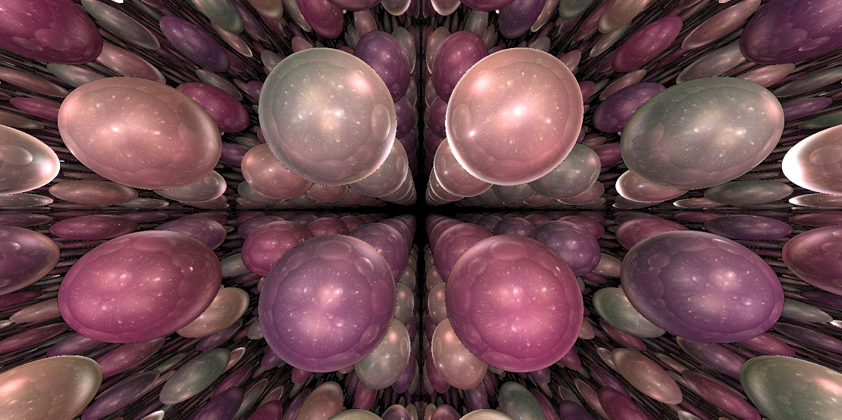
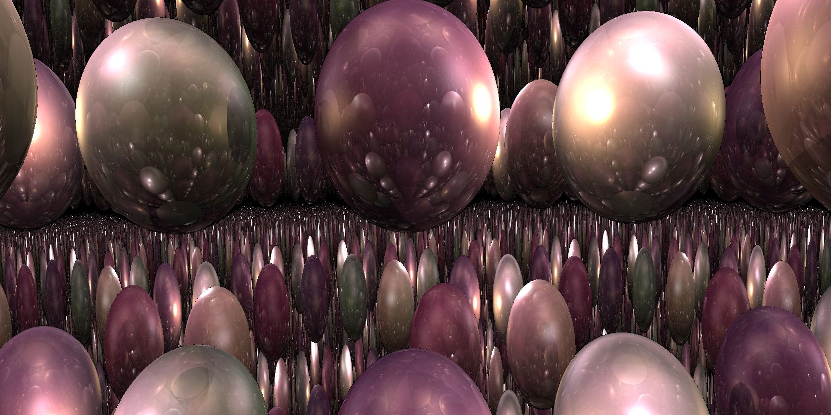
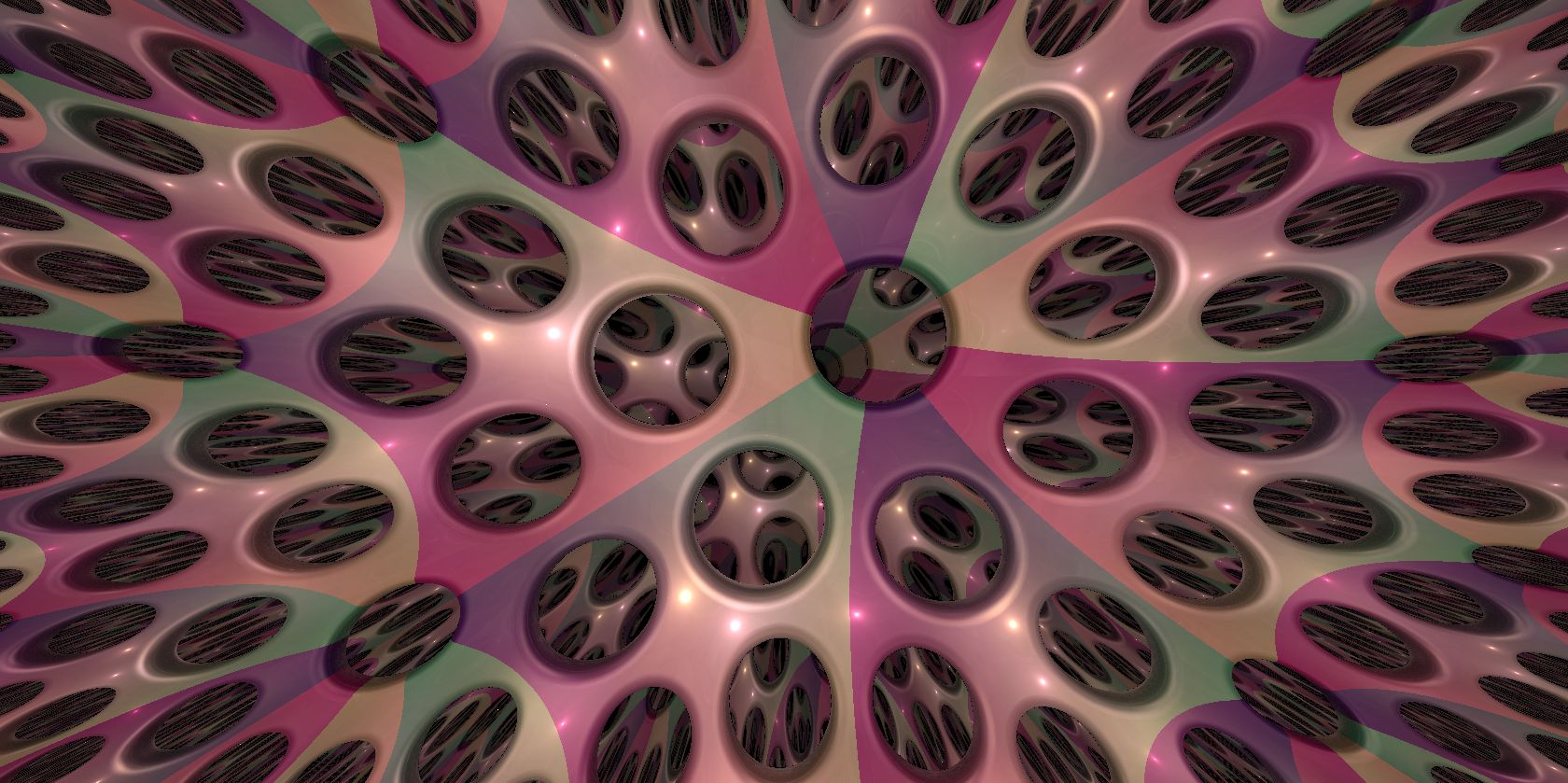
The manifolds with geometry are classified in [Sco83, Theorem 4.13]. In Figure 8.6, we show the in-space view for various scenes in geometry. All of these images show the orbifold which is the product of a circle with a torus containing a cone point of angle . Figures 8.6a and 8.6b show a collection of spheres, four in each fundamental domain. Figure 8.6c shows a slab , with four holes cut from the fundamental domain of , and a further hole cut around the cone point.
9. Nil
9.1. Heisenberg model of Nil
There are several models for Nil. Probably the most commonly used is the Heisenberg model (also known as the polarized model of the first Heisenberg group). The Heisenberg group is the group of upper triangular matrices of the form
We identify this with through the -, -, and -coordinates. The metric
is invariant under the left action of on itself.
The space has a major drawback for our purposes. To see this, let be point (corresponding to the identity matrix) which we see as the origin of the space. The group of isometries of fixing is isomorphic to . In particular, it contains a one-parameter subgroup of rotations. These rotations are difficult to visualize in the Heisenberg model of Nil. See Figure 9.1.

9.2. Rotation invariant model of Nil
For our computations we use a “rotation invariant” model of Nil. The underlying space of the model is the affine subspace of defined by . The group law is as follows: the point acts on on the left as the matrix
The origin is the point . Its tangent space is identified with the linear subspace of given by the equation . Our reference frame is where is the standard basis of . The metric tensor at the point is now given by
The map
is an isometry between the Heisenberg model and the rotation invariant model of Nil. For every , we write for the transformation with matrix
One can check that is an isometry of , rotating by angle around the -axis. Let be the transformation with matrix
This is another isometry of , in this case it flips the -axis, and satisfies . These two kinds of isometries generate the stabilizer of in .
9.3. Geodesic flow and parallel transport
The solution of the geodesic flow in the Heisenberg model of Nil has been computed, for example in [Mol03]. We could convert the solution into our rotation invariant model . Instead, we take this opportunity to illustrate Grayson’s method (Sections 3.2.1 and 3.4.1) and calculate the geodesic flow and parallel-transport operator directly in , as follows.
Let be a geodesic in Nil and be the corresponding parallel-transport operator. We define two paths and by the following relations
Recall that the identification of parallel transport with the path in is done via our reference frame at the origin . After some computation, Equations (3.2) and (3.6) respectively become
and
For the initial condition , where and satisfy , one gets
In order to get the expression for , we follow the strategy detailed in Section 3.4.1 and obtain
where
and
Note that is the differential of the rotation written in the reference frame .
Let us now move back to the original geodesic , which we write as
Without loss of generality we can assume that . Equation (3.1) becomes
Plugging in our solution for , we finally get
| (9.1) |
and otherwise
| (9.2) |
Remark 9.3.
If is very small but not zero, the above formulas are the source of significant numerical errors. This is due to the term
see Section 2.4.1(2). In practice, this causes noise around the -plane, see Figure 9.2. To fix this issue, when is small, we replace the formula given in Equation (9.1) by its asymptotic expansion of order seven around zero. ∎
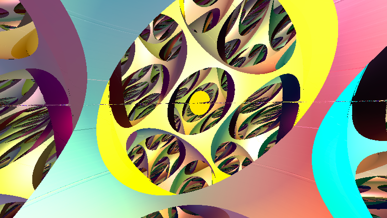
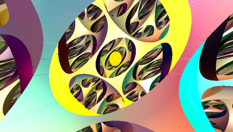
9.4. Distance to a vertical object
Observe that Nil comes with a natural -Lipschitz projection , sending to . In analogy with objects in the product geometries, we call the pre-image under of any non-empty subset of a vertical object. For example, any affine plane with equation is a vertical object.
Lemma 9.4.
Let be a subset of and the associated vertical object. The distance from any point to coincides with the distance between and in .
Proof.
Any isometry of preserves the fibers of the projection and induces an isometry of . Hence, applying a translation, it suffices to prove the claim in the case that is the origin . Similarly, applying a rotation, we can assume that the projection on is a point of the form , with . Since is -Lipschitz, we have
Let us explain the reverse inequality. We have seen previously that the map , mapping to , is a geodesic of Nil. Hence the distance in Nil between and the pre-image of is at most . Consequently
Figure 9.3 shows a vertical half-space in Nil. We texture the boundary with squares of side length one in its euclidean metric. Note that here (and in Sections 10 and 11) we extend the notion of a half-space from that given at the start of Section 3.7: the boundary may not be totally geodesic. Figure 9.12c shows vertical solid cylinders.
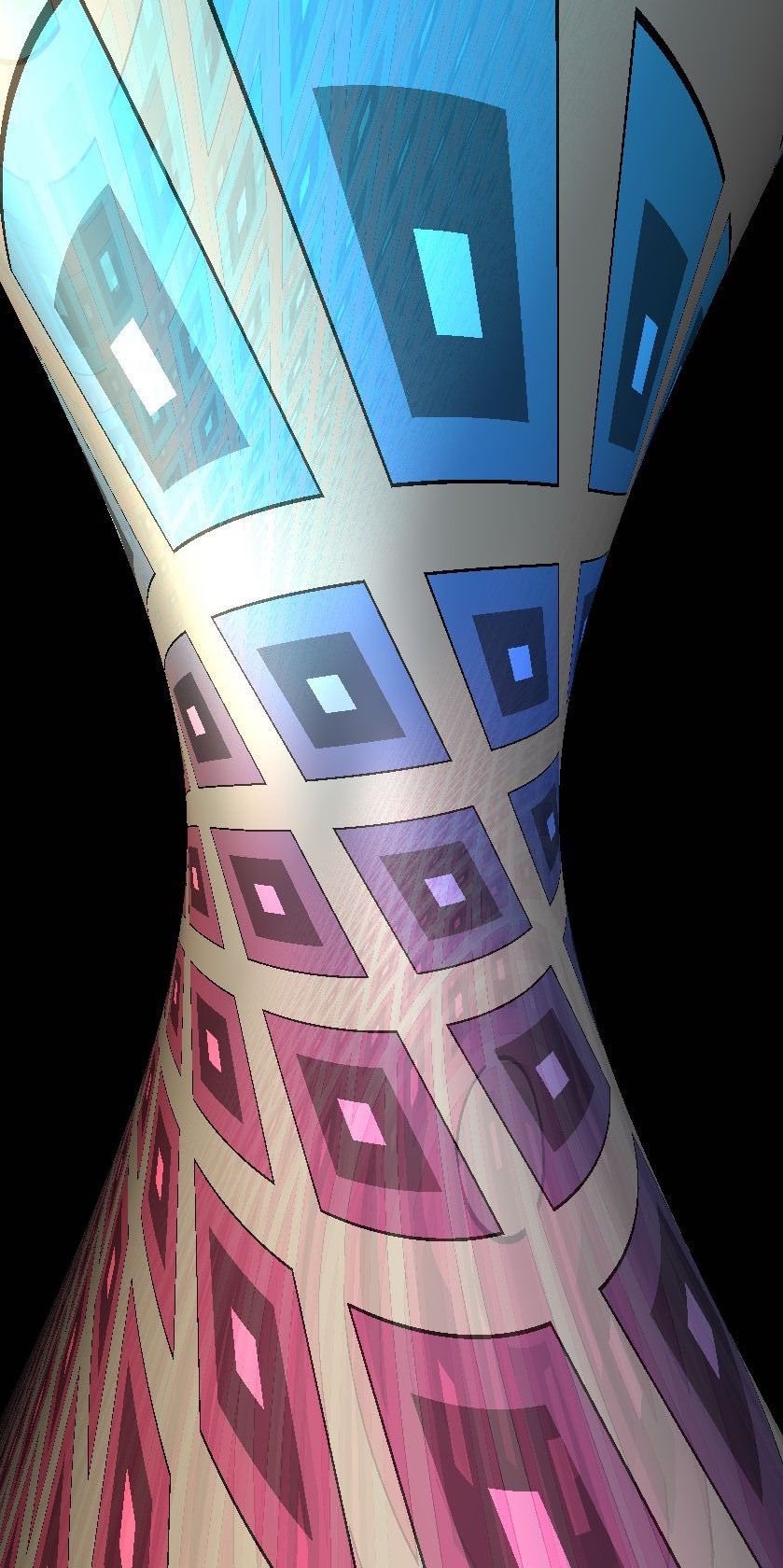
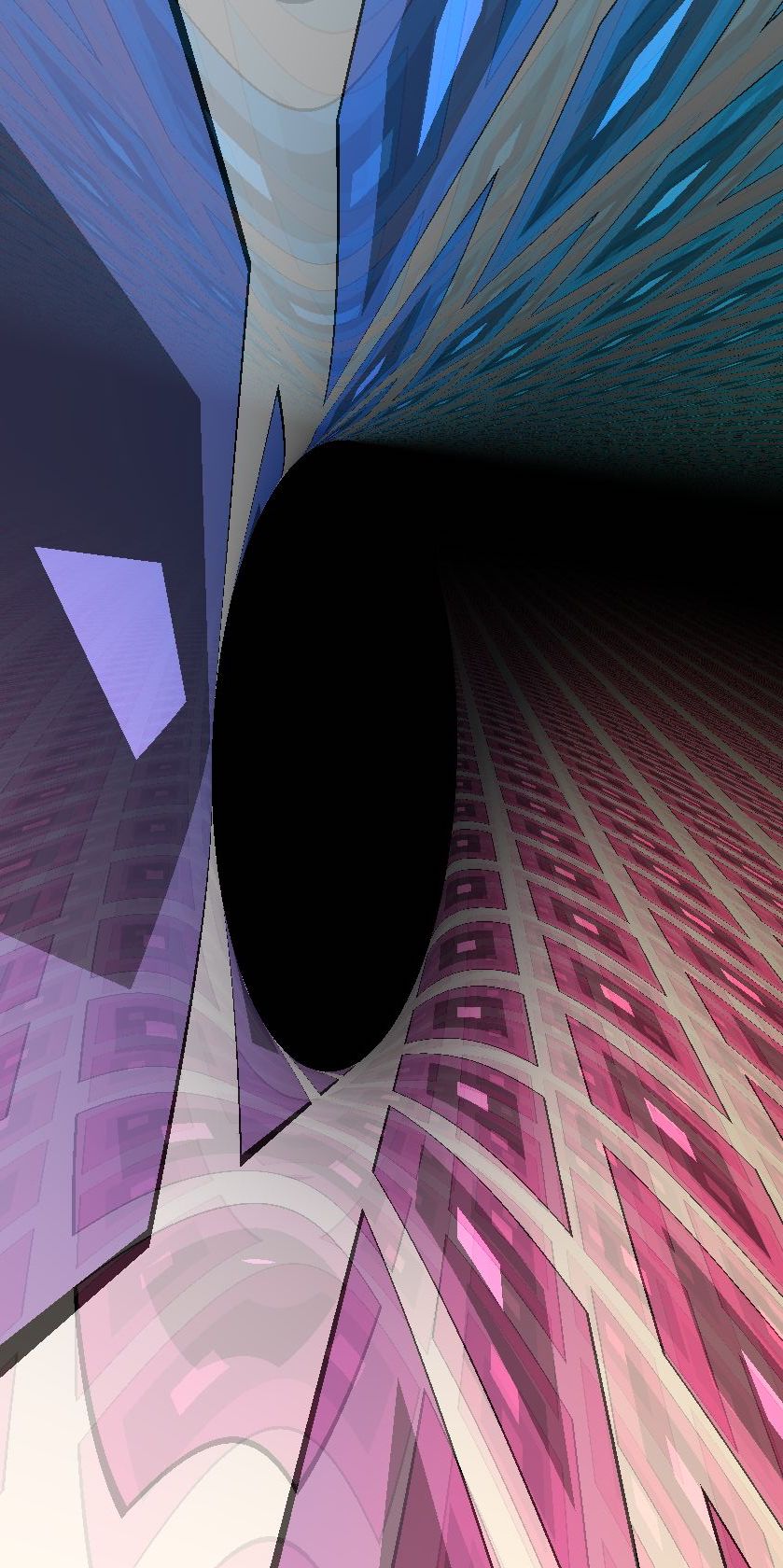
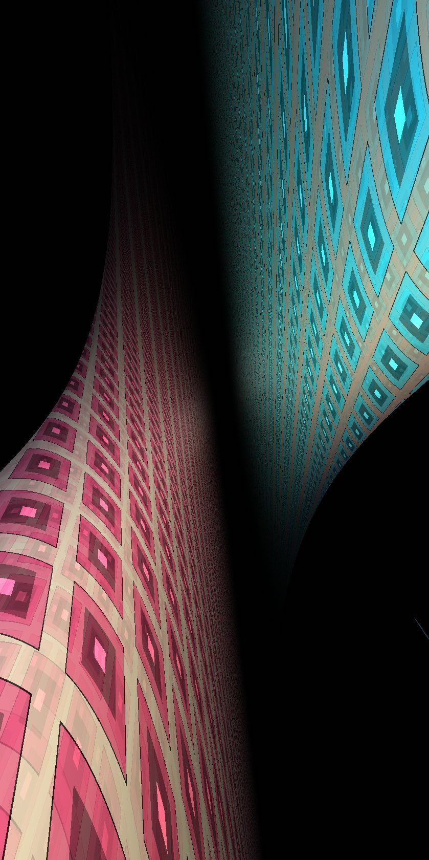
9.5. Exact distance and direction to a point
Since is homogeneous, we only need to compute the distance between any point and the origin. In order to calculate lighting pairs, we need to compute the direction at the origin of the geodesics from to . Unfortunately, in Nil there is no closed-form expression for either of these two quantities. We compute both using the same numerical approach. Using the flip symmetry, we may assume that the coordinates of satisfy .
Assume first that the point lies neither on the -plane nor on the -axis. Let be a geodesic from to . That is, and , for some . As in Section 9.3, we write for its (unit) tangent vector at . We deduce from Equation (9.1) that
where and . These quantities have the following useful geometric interpretation:
-
•
is the distance in between and , and
-
•
is the angle described by the projection of in .
Computing the directions from to consists of solving a system with five unknowns (, , , , and ) and five equations (the three given by Equation (9.1) along with the relations and ). Once has been found, it is an exercise to uniquely recover and by directly solving the equations. Hence there is a one-to-one correspondence between the geodesics joining to and the zeros of the function
see Figure 9.4.

A geodesic is minimizing if and only if the corresponding angle belongs to . It turns out that is strictly convex on the interval for every integer . Moreover, it is increasing on . In order to find the minimizing geodesic from to we numerically compute the unique zero of on using Newton’s method.
For physically accurate lighting, we also need the lighting pairs, , as defined in Section 5.6. Using binary search, we find a value of where is positive and is negative. We then run Newton’s method, starting from , producing a sequence . Recall that is strictly convex on . Hence if the equation admits a solution in this interval, then will converge toward the first such solution. Otherwise, either escapes the interval , or the sign of the derivative becomes positive. Either case is a halting condition for our algorithm. Repeating this procedure starting with a point for which is positive, we find the other solution in the interval. Depending on the level of precision that we want for lighting, we can repeat the procedure on the next intervals , , …
Assume now that lies in the -plane. Then there is a unique geodesic joining to . It coincides with the euclidean geodesic of between the same points. Hence its direction and length can be computed explicitly. Alternatively, using continuity, we can extend the definition of the previous function at by letting . In this way, this particular case is included in the previous discussion. Indeed the only zero of is .
If lies on the -axis, then the path is a geodesic from to with initial direction and length . If , for some integer , then and are joined by other rotation-invariant families of geodesics where runs over . The th of these has length
and direction at the origin
9.6. Distance underestimator for a ball
As mentioned in Section 2.2, we don’t necessarily need the exact distance to an object to perform ray-marching. A distance underestimator also works. A rough estimate using the solution of the geodesic flow shows the following.
Lemma 9.5.
Let be the continuous increasing map defined by
If is a point at distance from the origin , then and . ∎
As a consequence, for every , for every , we have
This allows us to build a distance underestimator to render a ball of radius centered at , as follows. Let
where
and is a constant that is much larger than the threshold used to stop the ray-marching algorithm. This is more efficient than the exact signed distance function: here, the rough (and inexpensive to calculate) estimate is used to handle points at a large distance from the ball. When the point is close to the ball we replace this estimate by the exact distance computed numerically as explained in Section 9.5. We use this distance underestimator to render the balls in Figure 5.13 (a line of balls along the fiber direction), and Figure 9.12b (a lattice of balls in Nil).
9.7. Creeping to horizontal half-spaces
In the case of vertical objects, we can use the geometry of Nil to help us build signed distance functions. For “horizontal” objects, for example the half-space, we do not have anything equivalent. Thus, it is difficult to come up with a signed distance function (or even a distance underestimator). However, we can still detect whether a point is in a half-space or not, and so we can use the same binary search algorithm as used to detect the boundary of a fundamental domain in Section 4.2.1. Figure 9.5 shows the half-space in Nil geometry, with boundary textured by squares in the coordinate grid of side length one.
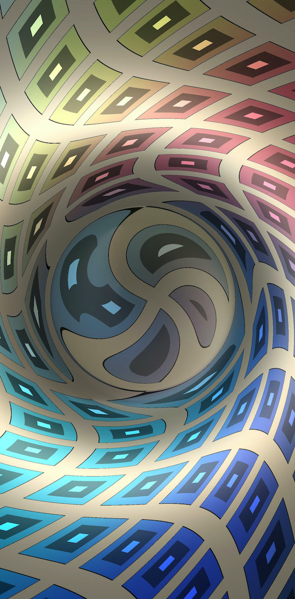
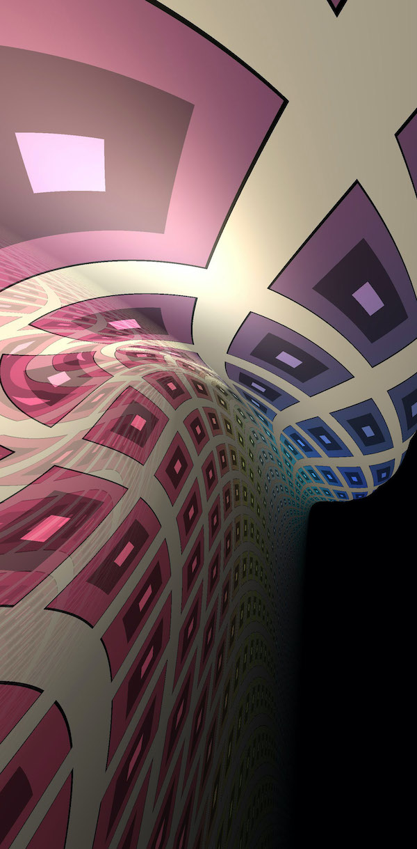
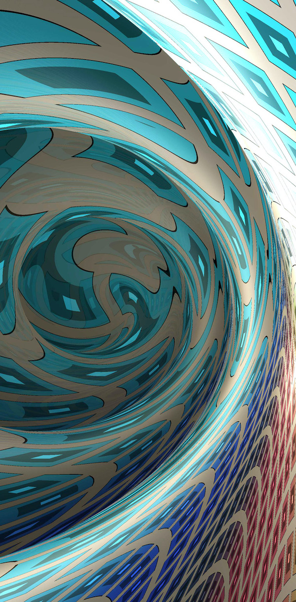
9.8. Lighting
We addressed the calculation of lighting pairs in Section 9.5. Here, we calculate the intensity experienced from an isotropic light source traveling a distance with initial tangent . Recall that this is inversely proportional to the area density . Here we calculate this area density directly by taking the derivative of the geodesic flow as in Equation (5.9).
A parameterization of the speed geodesic starting at the origin with arc length parameter in the direction is given by Equation (9.1) for the generic case (when ) and by Equation (9.2) for geodesics in the -plane. Below we concern ourselves with the generic case. Let be the cylindrical coordinates on with the norm of the projections onto the plane and axis respectively, and measured from the positive axis. In these coordinates the point is expressed . Thus, using Equation (5.13) we may calculate the area density in terms of the and derivatives of Equation (9.1).
| (9.6) |
See Figure 9.6. As with the computation of the geodesic flow in Section 9.3, to obtain correct lighting along the plane direction, one should use the asymptotic expansion of Equation (9.6) around .
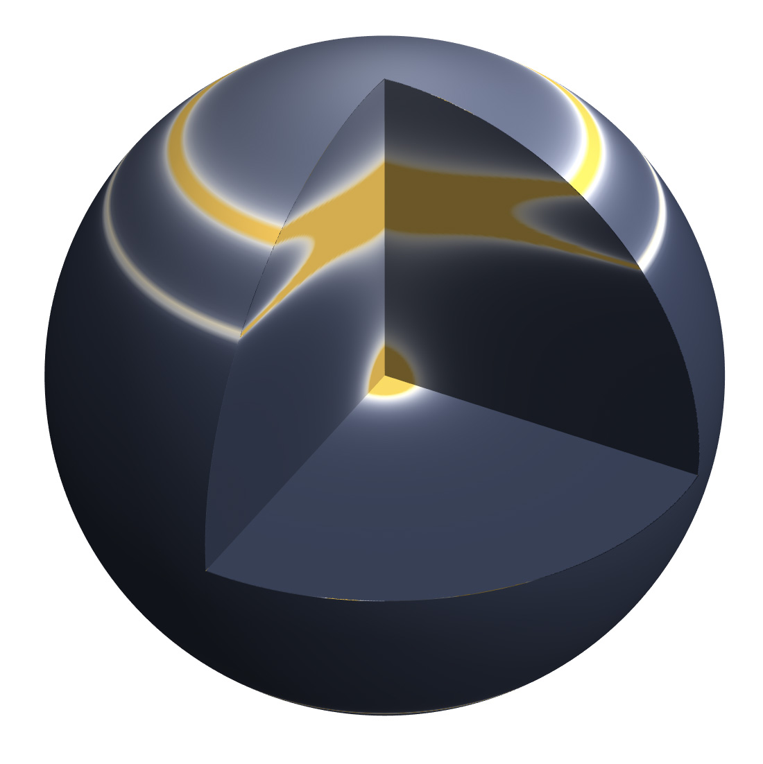
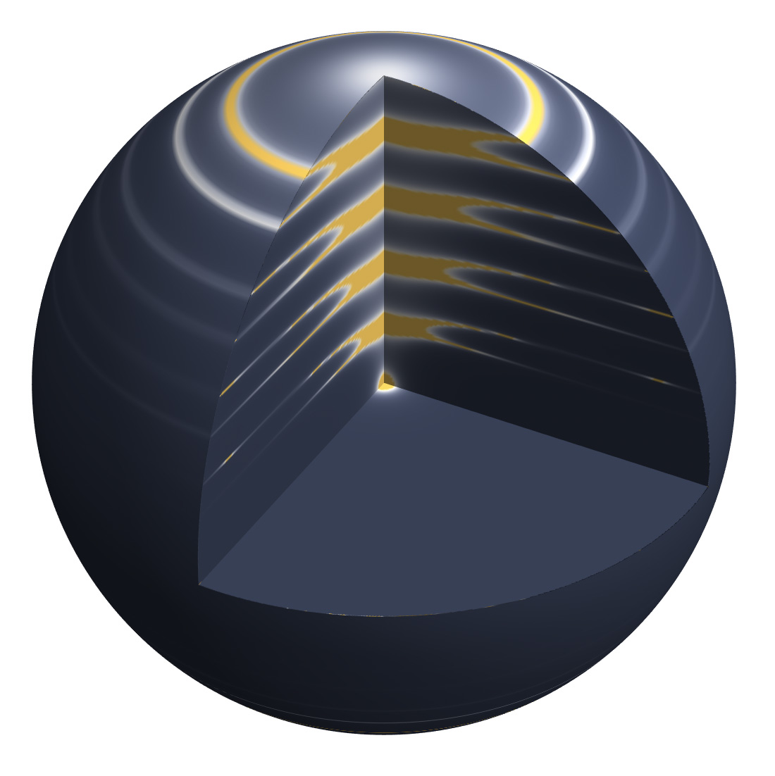
In horizontal directions, the light intensity quickly drops away. Near the vertical axis, the intensity of a light source periodically blows up as geodesics reconverge. See Figures 9.7, 9.8, 9.9, and 9.10.
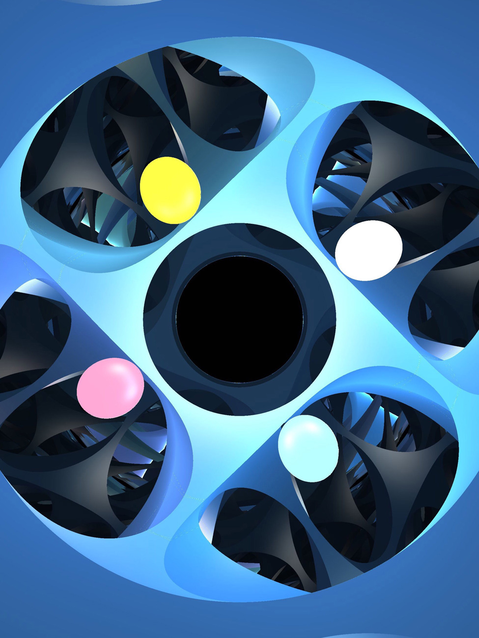
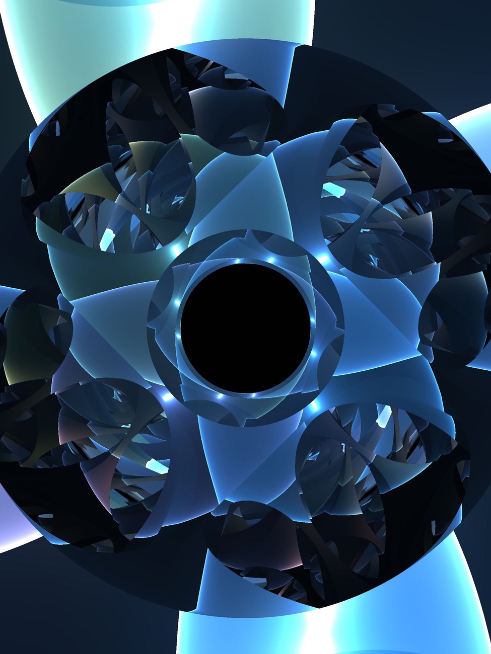
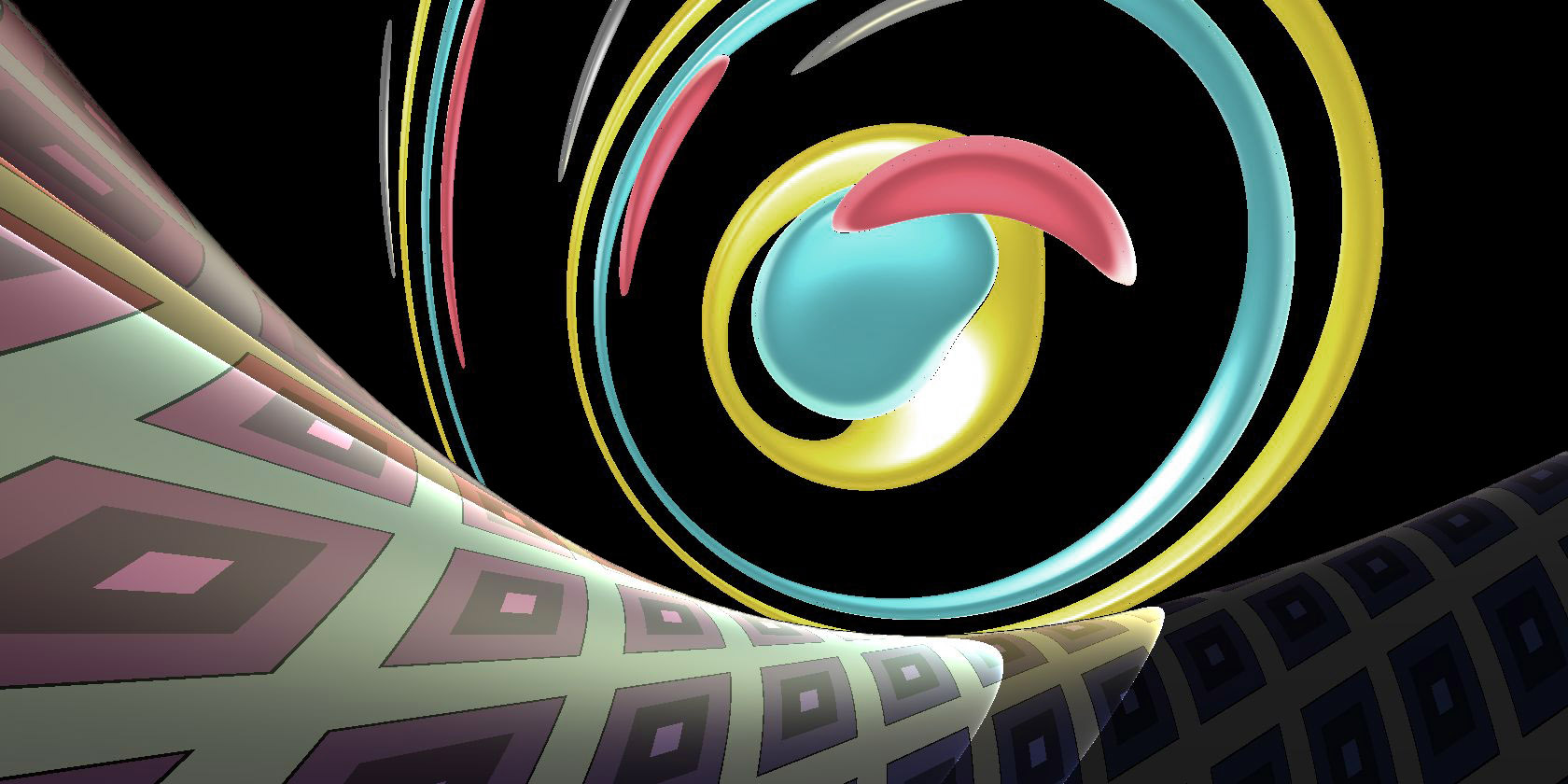
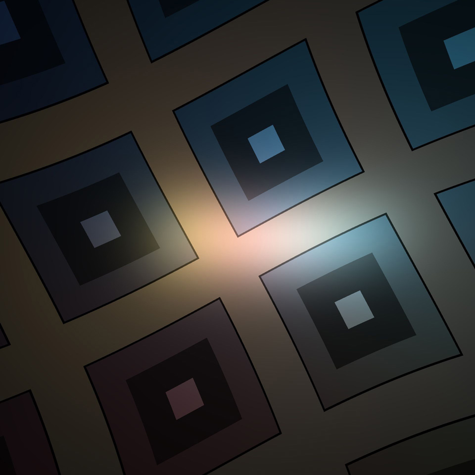
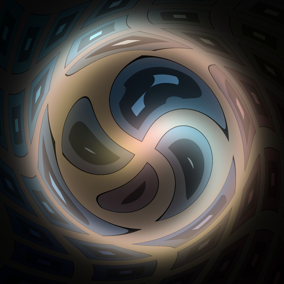
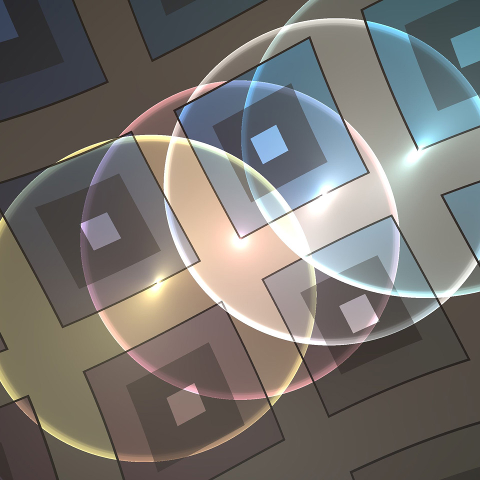
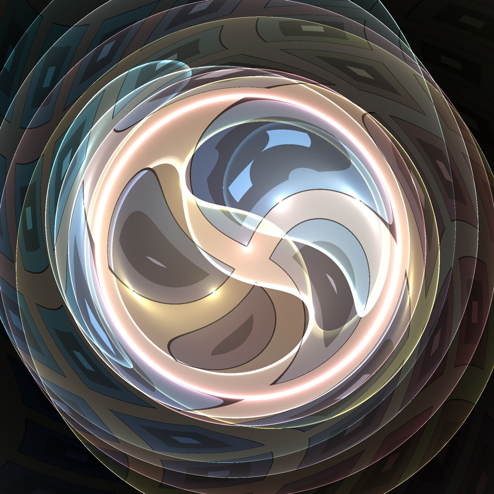
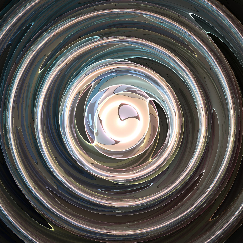
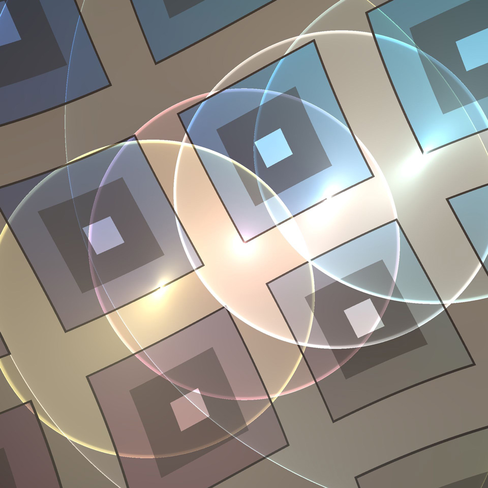
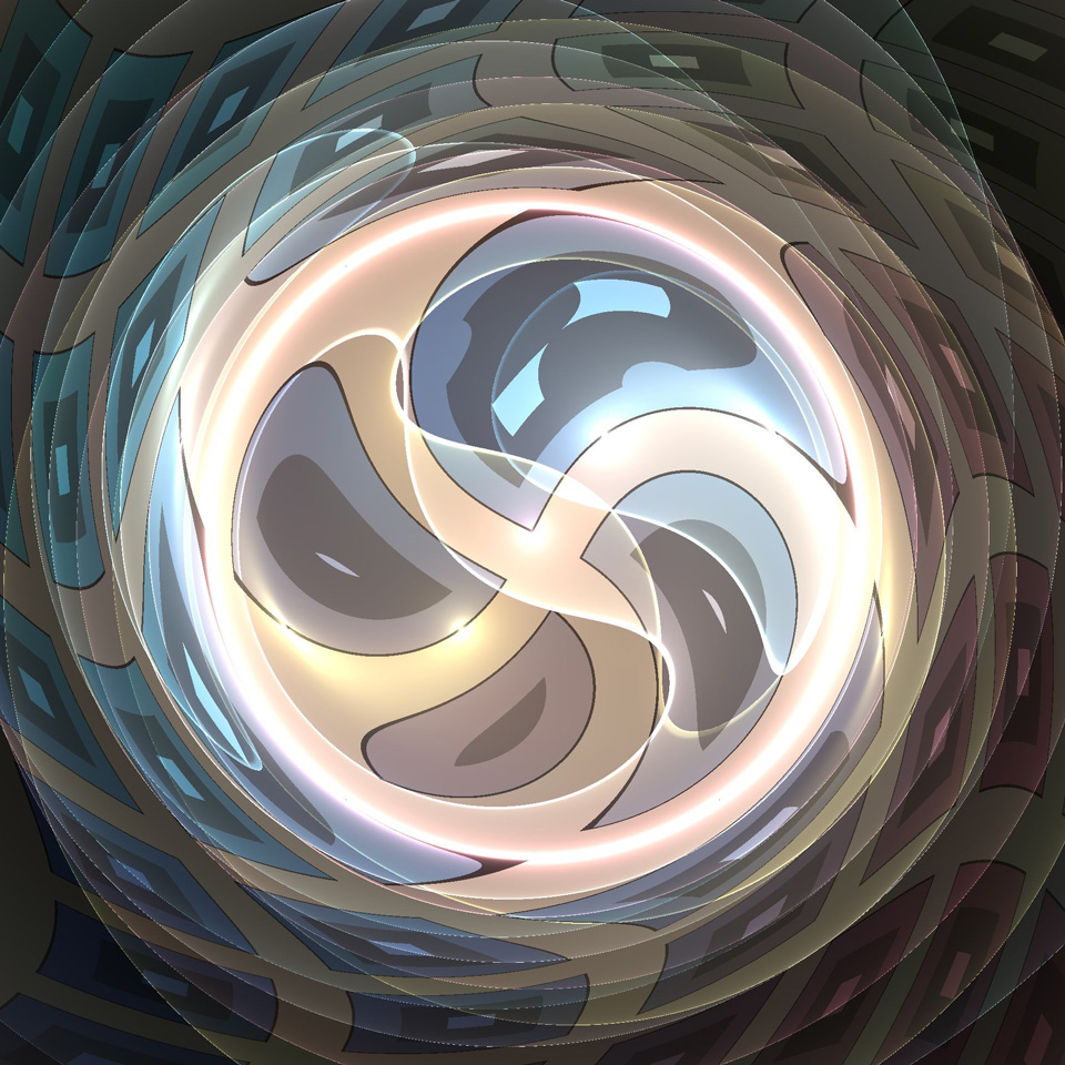
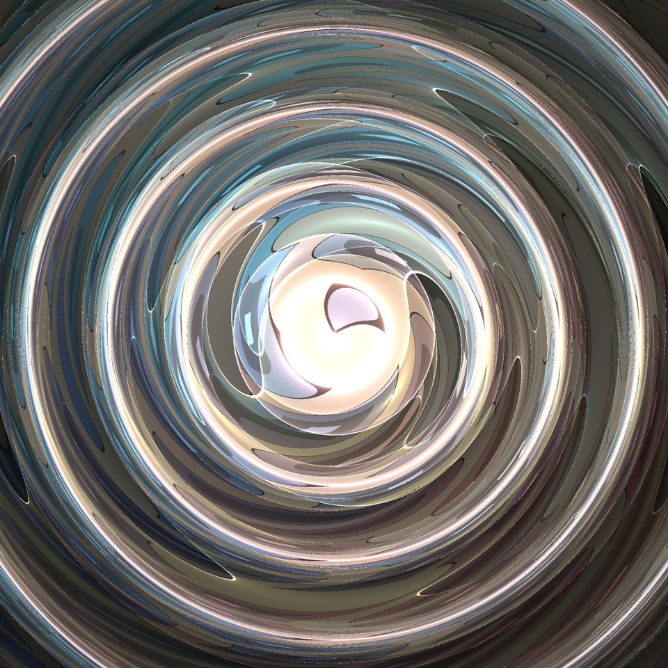
9.9. Discrete subgroups and fundamental domains.
The compact Nil manifolds are circle bundles over euclidean two-orbifolds with non-zero Euler class [Sco83, Theorem 4.17]. The simplest example of a Nil manifold can also be seen as the suspension of a regular two-torus by a Dehn twist. The fundamental group of is a lattice in . We explain here with a concrete example how to construct a fundamental domain for the action on on .
Let be the Dehn-twist of the standard two-torus with action given by the matrix
Consider the Dehn-twist torus bundle which is the mapping torus of with monodromy . Its fundamental group has presentation
Here and can be interpreted as the standard generators of . The conjugation by is the automorphism of induced by . Note that is central, hence corresponds to the loop along which we are performing our Dehn twist. The group is actually generated by and only. Nevertheless it is more convenient to keep three generators as they represent translations in three independent directions. The group can be identified with the discrete Heisenberg group, that is the set of points with integer coordinates in the Heisenberg model of Nil. (Recall that is the rotation-invariant model of Nil. Hence the group is not the set of integer points in . This set is actually even not a subgroup.) Concretely, , , and are the elements of Nil whose coordinates in are
Observe that via the projection , every element of induces an isometry of : and correspond to translations along the - and -axis respectively, while acts trivially on . It follows that the “cube”
is a fundamental domain for the action of on . Note that , and do not directly pair the square sides of the “cube”. See Remark 9.7. Our rotation-invariant model for Nil is also a projective model. The fundamental domain can be seen as the intersection of a collection of half-spaces , , as described in Section 4.1.2. Here
while and are defined in the same way. The teleporting algorithm has two main steps. Let be a point in .
-
(1)
If does not belong to (respectively , ), then we move it by (respectively , , ). After finitely many steps, the new point will lie in
The isometries of induced by and commute, so we don’t pay attention to the order in which we perform these operations.
-
(2)
Once this is done, if does not belong to (respectively ), then we move it by (respectively ). Note that does not affect the -coordinates of . Therefore, after this process, lies in .
Remark 9.7.
Note that the collection of isometries does not provide a face pairing of our fundamental domain in the sense of Section 4.1. Consider for example the square sides and which are the intersections of with the affine planes and respectively. The generator is a shear, not an affine translation in along the -axis. See Figure 9.11a. Thus it does not map to . In order to get a proper face pairing, one must subdivide the sides of and increase the number of generators. This is illustrated on Figure 9.11b. We draw the one-skeleton of and color the sides (on the left) and (on the right). The yellow (respectively blue, red) face in is mapped bijectively to the face with the same color in via (respectively , ).
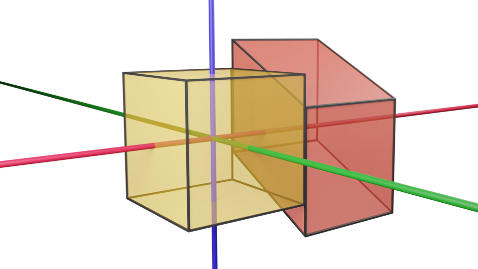
2pt \pinlabel at 250 375 \pinlabel at 200 543 \pinlabel at 223 175 \pinlabel at 104 541 \pinlabel at 89 422 \pinlabel at 129 310 \pinlabel at 100 620 \pinlabel at 226 274 \pinlabel at 23 570 \pinlabel at 312 214
at 550 411
\pinlabel at 465 569
\pinlabel at 354 626
\pinlabel at 338 360
\pinlabel at 323 531
\pinlabel at 360 439
\pinlabel at 458 363
\pinlabel at 493 660
\pinlabel at 320 421
\pinlabel at 572 584 \endlabellist
A similar subdivision can be found for the sides and . (No subdivision of the horizontal faces of is needed as is an affine translation along the -axis.) As explained in Remark 4.3 and illustrated by the above algorithm, when using a fundamental domain defined as the intersection of projective half-spaces, we do not need a proper face pairing to implement teleportation. ∎
In Figure 9.12, we show the in-space view for various scenes in Nil geometry. Figure 9.12a shows the Dehn-twist torus bundle with monodromy as in Section 9.9, with a fundamental domain drawn in the style of Figure 2.1b. Figure 9.12b shows a lattice of spheres, textured as the Earth, lit by a corresponding lattice of light sources. Figure 9.12c shows solid cylinders (which we implement as vertical objects) around fibers of Nil. Compare with Figure 8.2.
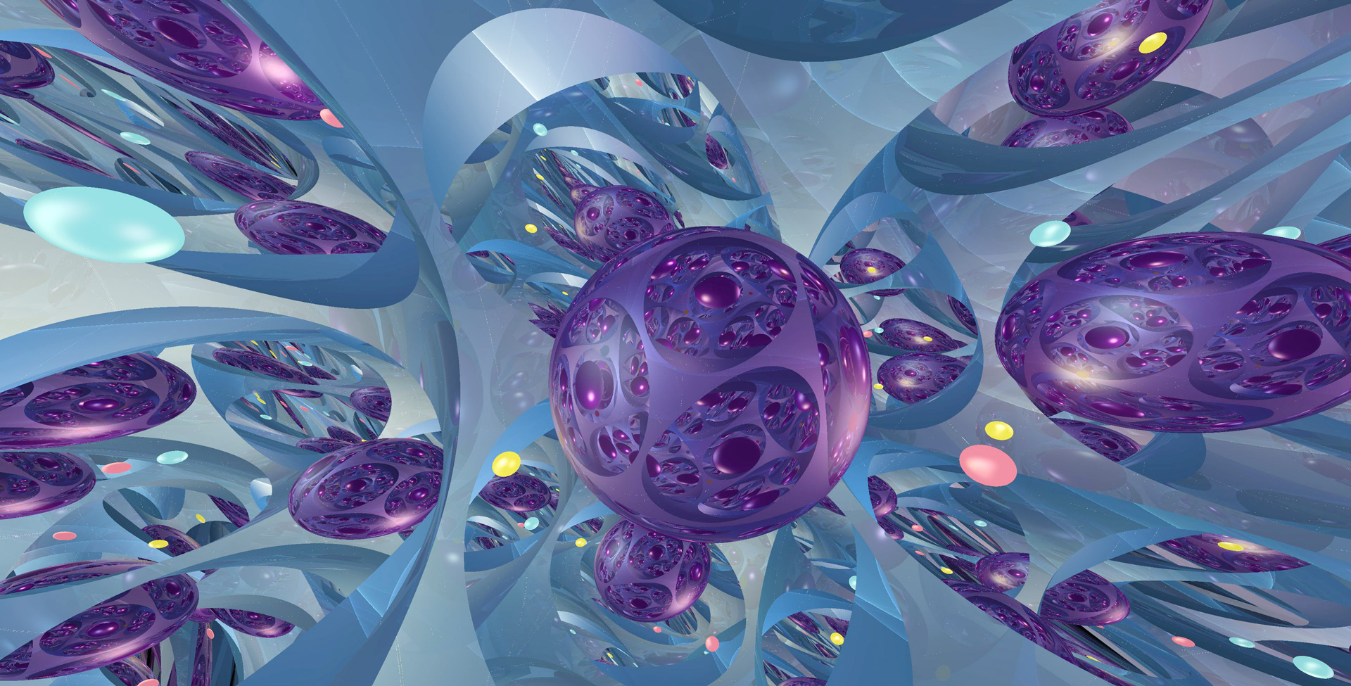
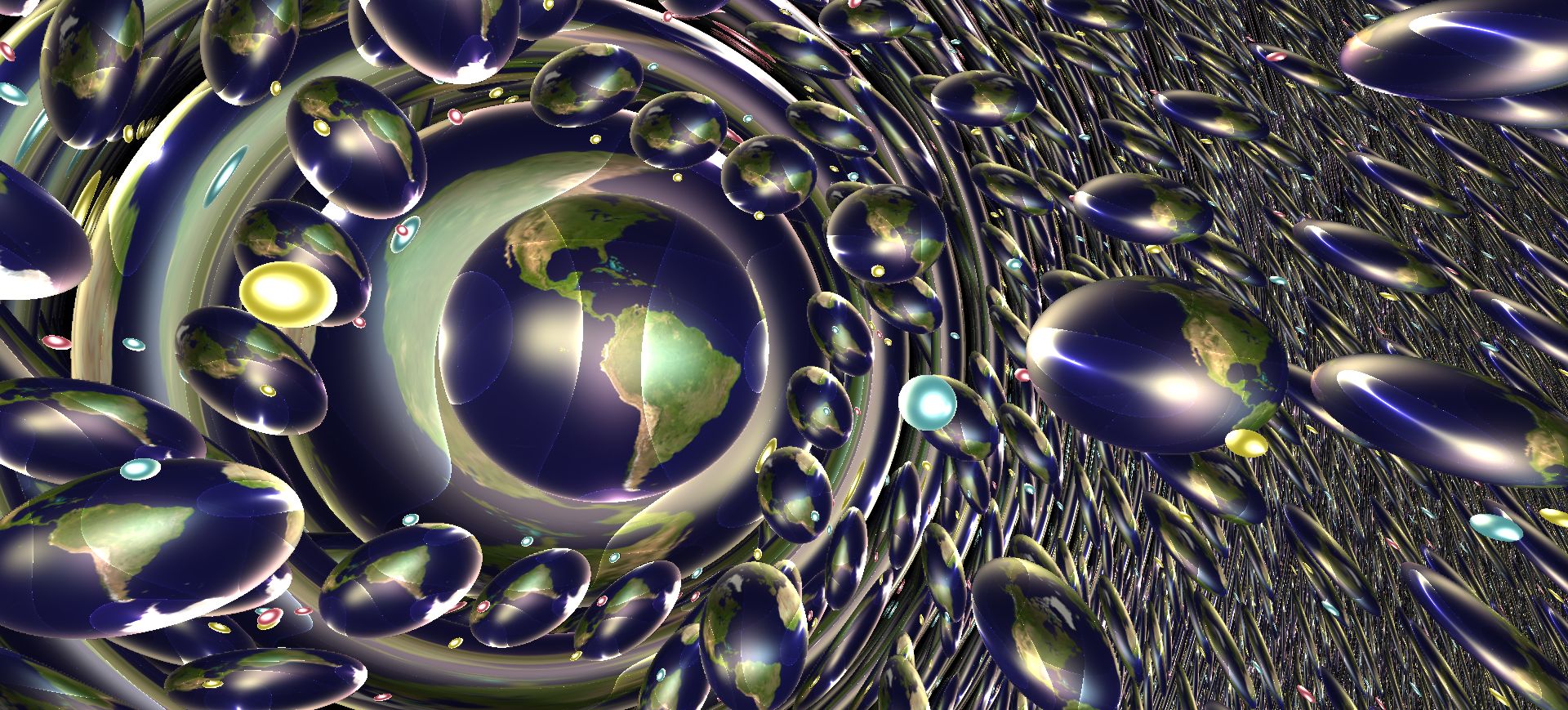
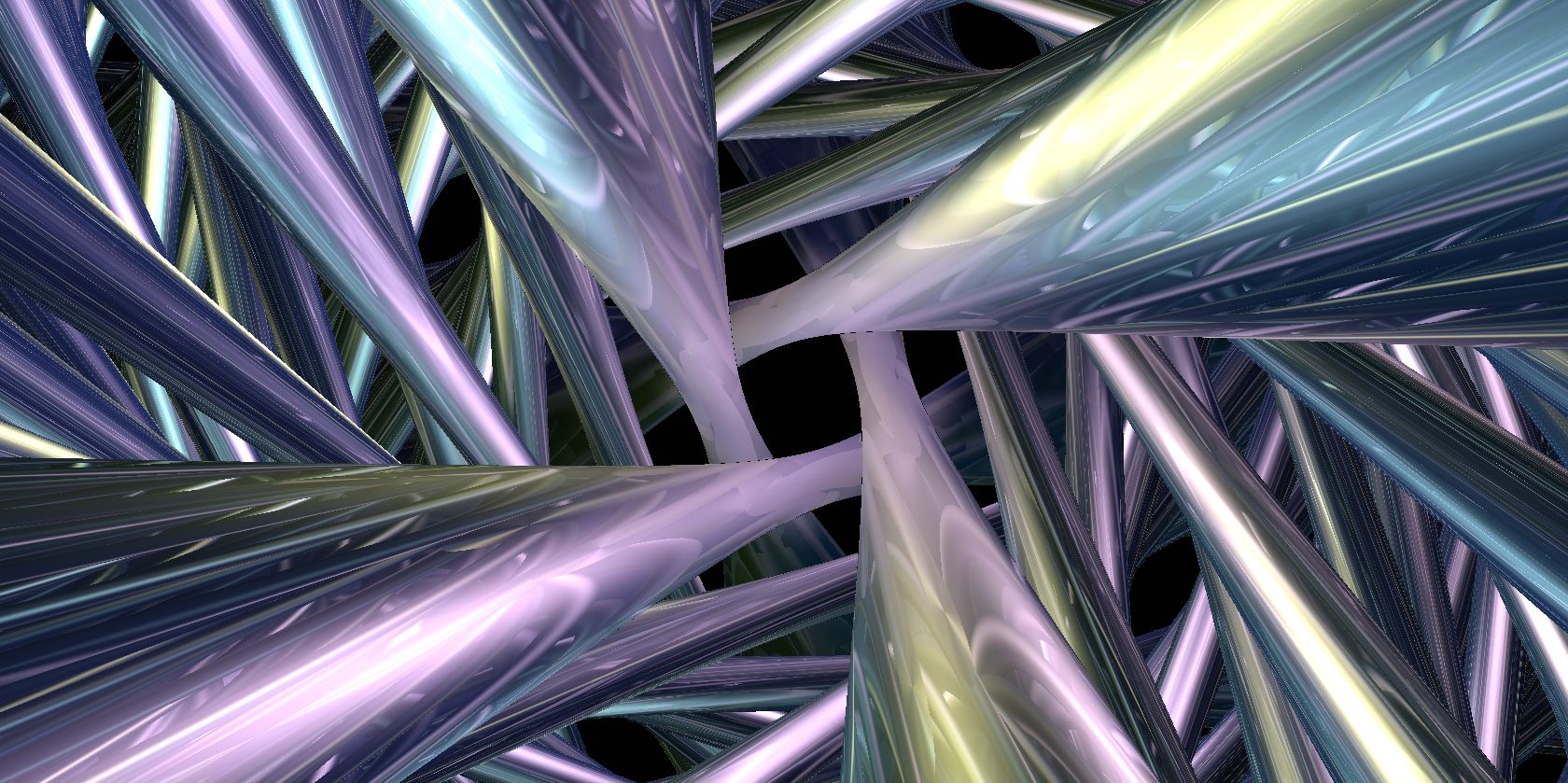
10.
10.1. Model
In order to build our model space, we view as a circle bundle over . This construction is analogous to the Hopf fibration . In the spherical case, conjugation by (thought of as the unit quaternions) defines an action by rotations on , seen as the Lie algebra of . More precisely, this action preserves the Killing form, which in this case has signature . In particular, after fixing a base point in the unit sphere of , the orbit map defines a projection from onto , whose fibers are circles.
We follow the same strategy for . The action by conjugation of on its Lie algebra preserves the Killing form which here has signature (2,1). The level set of this form is a model . As above, the orbit map defines a projection from onto , whose fibers are also circles. Topologically this realizes as a trivial bundle homeomorphic to . Its universal cover is homeomorphic to . This is the description we use for our model.
We now give detailed computations. We identify the space of -matrices with via the basis given by
The quadratic form is diagonal in this basis: given any point in , we have
In particular and correspond to the subsets
of . We choose for the origin the point . This corresponds to the identity. The group law can be rewritten as follows: given a point in , the corresponding element of acts on as the matrix
We endow with an -invariant riemannian metric:
where
It turns out that the level sets of are totally geodesic subspaces of . The stabilizer of the origin is generated by:
-
•
rotations of angle , with matrix
-
•
the flip , with matrix
Observe that , so is isomorphic to .
The space we are really interested in is not , but its universal cover. Topologically, the latter is a line bundle over . The identification goes as follows. Consider the adjoint representation of on its Lie algebra
This action preserves the Killing quadratic form
which has signature . Hence it induces an action by isometries on the hyperboloid model of . In our context, the Lie algebra is isomorphic to the linear space spanned by
The Killing form is diagonal in this basis: if , then . So we choose for the hyperboloid model of the set as defined in Section 8.1:
We define a -Lipschitz, -equivariant projection by sending the origin to the point . (The scaling factor four in the metric on was precisely chosen so that the best Lipschitz constant for is one.) The fiber of the point is a circle parametrized as follows.
where is the section given by
and is the transformation of with matrix
Note that translates points along the fiber by an angle , not . This accounts for the fact that the map is a two-sheeted cover. Finally one observes that the projection
is a covering map, providing an identification between and our model space . We call the factor (respectively ) the horizontal (respectively vertical or fiber) component of .
Remark 10.1.
In practice, we adopt a slightly different point of view. We store a point as a pair where is the image of by the covering map and is the fiber component of . This representation is redundant, but allows us to go quickly back and forth between and its universal cover. ∎
We choose as a base point of the point which is a pre-image of . The covering map induces an isomorphism between the stabilizer of and the stabilizer of , that is .
-
•
We choose a lift of with the following properties. It fixes the fiber component, and acts on the horizontal component as the usual rotation of by angle centered at . Beware that is a rotation of our model space of which is distinct from the element of representing a rotation of .
-
•
The map sending of to is a lift of .
10.2. Geodesic flow and parallel transport in
The solution of the geodesic flow has been computed in [DESS09]. We follow a slightly more geometric approach.
Since the covering map is a local isometry, the geodesics of are lifts of geodesics in . Hence we first integrate the geodesic flow in using Grayson’s method. We endow the tangent space with the reference frame , where
We write for its image under . (Note that and coincide with the previous definition.) It follows from our choice of metric that is an orthonormal basis of .
Let be a geodesic in and let be the corresponding parallel-transport operator. As in Sections 3.2.1 and 3.4.1, we define paths and by the relations
After some computation, Equations (3.2) and (3.6) can be written relative to the basis as follows
and
For the initial condition , where and satisfy , one gets
In order to calculate the expression for , we follow the strategy detailed above and obtain
where
and
Note that is the differential at of the rotation , written in the frame .
Let us now move back to the original geodesic . Equation (3.1) becomes , where
Using a change of variables, one can reformulate the previous equation into a first-order differential system with constant coefficients that we integrate with standard methods. We obtain that the geodesic , such that and , decomposes (up to a rotation) as a product of two one-parameter subgroups:
| (10.2) |
As before, is the rotation of by angle and is group multiplication in . The spin factor represents a rotation of fixing the origin . It can be written in as
The translation factor can have three forms, corresponding to the three types of isometries of . For simplicity we let .
-
•
If , then is an elliptic transformation, given in by
-
•
If , then is a parabolic transformation, given in by
-
•
If , then is a hyperbolic transformation, given in by
10.3. Passing to the universal cover
Let us now consider the geodesic in the universal cover starting at with initial velocity . This is a lift of the geodesic computed above. The horizontal component of is obtained as the image of under the projection . Note that the spin factor fixes the base point . Moreover, the rotation of induces (via the projection ) the rotation of by angle centered at . Consequently, is the image under of one of the following points, depending on whether , , or respectively:
These are parametrizations of orbits under the one-parameter subgroups above. Their images are a circle, a horocycle, and an equidistant curve to a geodesic, respectively.
In order to compute the fiber component of it is convenient to introduce cylindrical coordinates on . Given , and , the point of with cylindrical coordinates is
This choice has been made so that the projection from (in cylindrical coordinates) to (in polar coordinates) is given by . In view of the expression for and its projection onto , we may calculate an expression for the fiber component of . This calculation is greatly simplified by the use of polar coordinates. We obtain
where is characterized by
Observe that if , then . Therefore its value can be computed from the above equation using the standard function. On the other hand, if , then the geodesic spirals, and the value of needs to be adjusted by the correct multiple of .
Note that the covering map is a local isometry. Hence the parallel transport operator in can be obtained by lifting the parallel transport operator in . In view of Grayson’s method, this operator is encoded by a local path , see Section 3.4.1. The identification relies on a choice of a preferred frame in the tangent space at the origin. By construction is equivariant with respect to the projection . Moreover it maps to our preferred frame in . Thus and actually coincide.
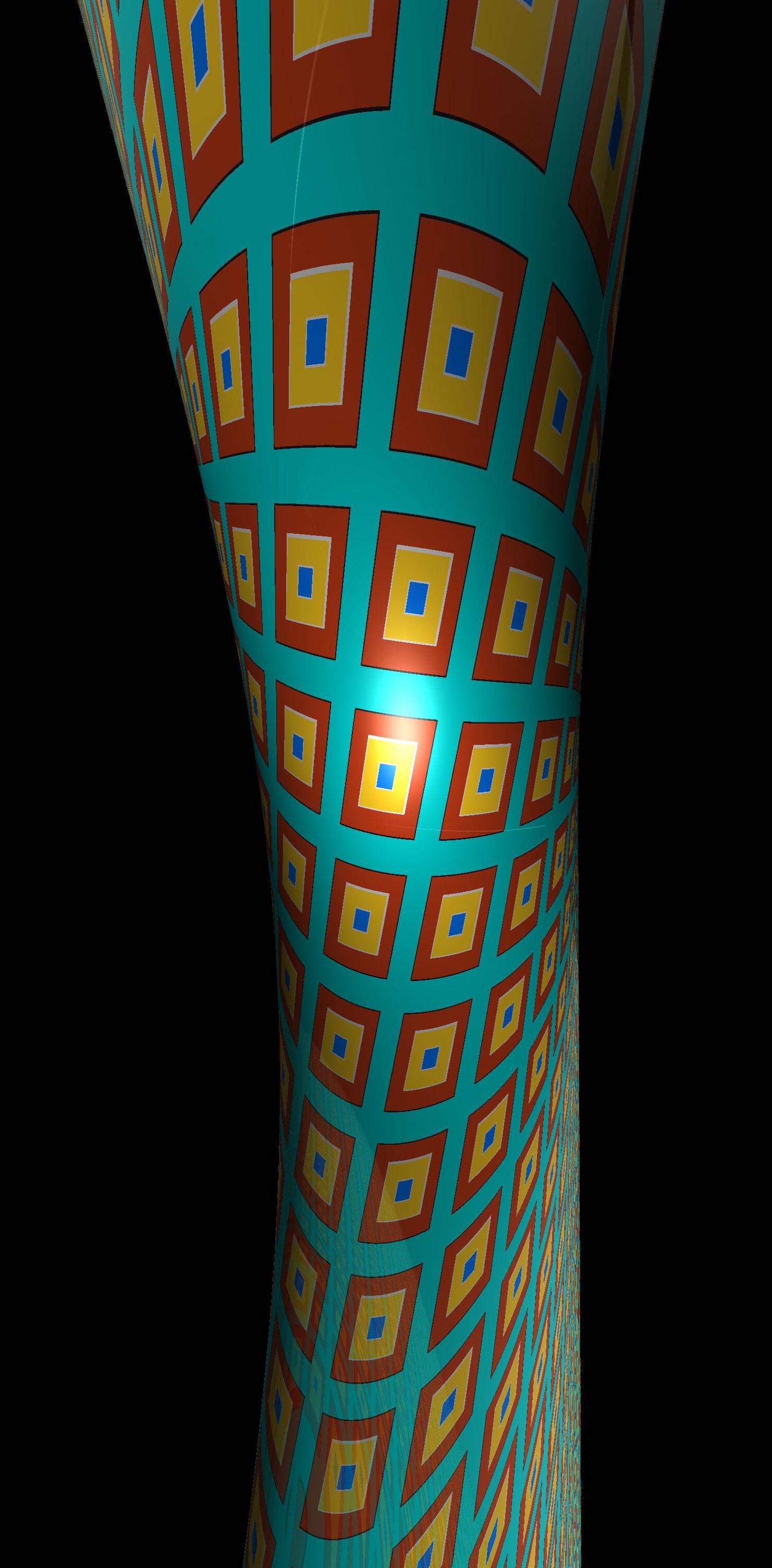
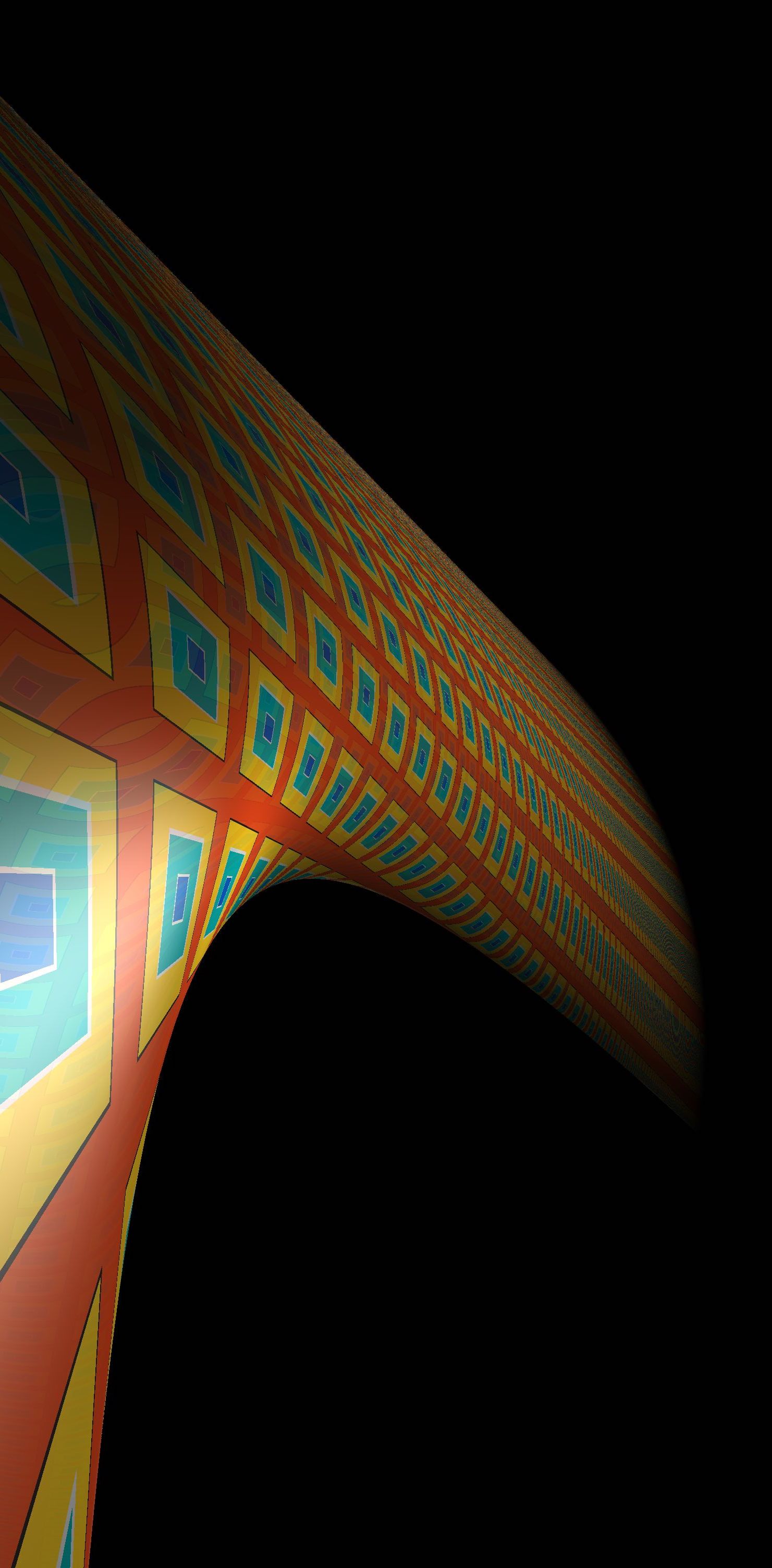
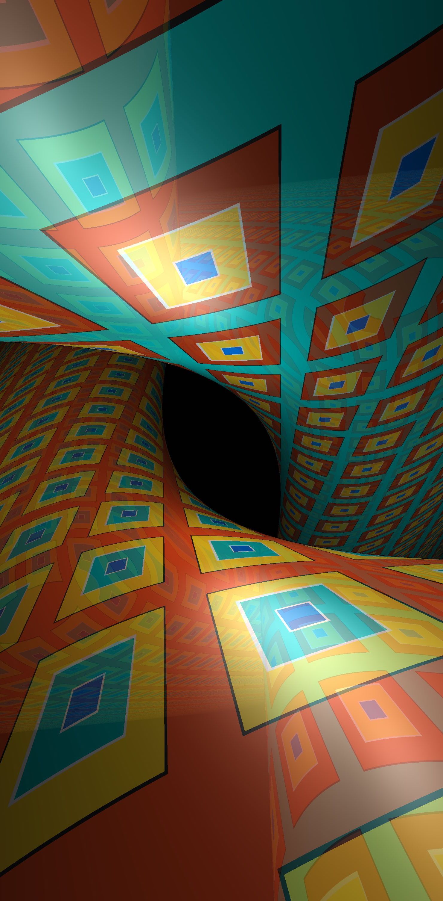
10.4. Distance to a vertical object
Exactly as in Nil, we say that an object is vertical if it is the pre-image of the projection of a non-empty subset of . In this situation, for any point we have
Figure 10.1 shows pre-images of a half-space with geodesic boundary in . The boundary of each is patterned with a square grid following the induced euclidean metric on the plane. The grid has side-length .
10.5. Exact distance and direction to a point
The strategy to compute the distance and direction from the origin to an arbitrary point with cylindrical coordinates is similar to the strategy used in Nil. Because of the flip symmetry, we may assume that . First assume that . Using the solution of the geodesic flow, we observe that the geodesics joining to are in one-to-one correspondence with the zeros of a function
| (10.3) |
We define this function in Figure 10.2; see Figure 10.3 for its graph.
Observe that along a given geodesic , the angle is a decreasing function of the time parameter . Said differently, when is moving up in the fiber direction, then its projection in turns clockwise. Hence the domain of is contained in . Moreover is decreasing around .

As in Section 9.5, we compute the zeros of using Newton’s method, and thus calculate the lighting pairs .
Assume now that . The path is a geodesic from to with initial direction and length . If , for some integer , then and are joined by other rotation-invariant families of geodesics , where runs over . Each geodesic in the th family has length
Moreover, the initial direction at the origin is characterized by
10.6. Distance underestimator for a ball.
As we explained in Section 10.1, is a (metrically) twisted line bundle over . As a subset of , our model for is identical to our model for (see Section 8). This gives an identification (of course, not an isometry) between and , which we use to approximate distances in as follows.
Lemma 10.4.
For every point , we have
Proof.
Consider an arc length parametrized geodesic joining to . We write for its length in . A computation shows that . Hence . Second, a similar calculation shows that the arc length parametrized geodesic of joining to is still parametrized by arc length when viewed as a path in . Consequently . ∎
Remark 10.5.
Note that the proof here relies on the fact that these geodesics begin at the origin, . The result does not hold for general geodesics. ∎
As in Nil, we use this observation to construct a distance underestimator to render a ball of radius centered at , as follows. Let
where
is half the distance from the origin to in , and is a constant that is much larger than the threshold used to stop the ray-marching algorithm. In the last case of , the exact distance is computed numerically as explained in Section 10.5. We use this distance underestimator to render the balls in Figure 10.4. Compare with Figure 5.13, which shows a line of balls in Nil.
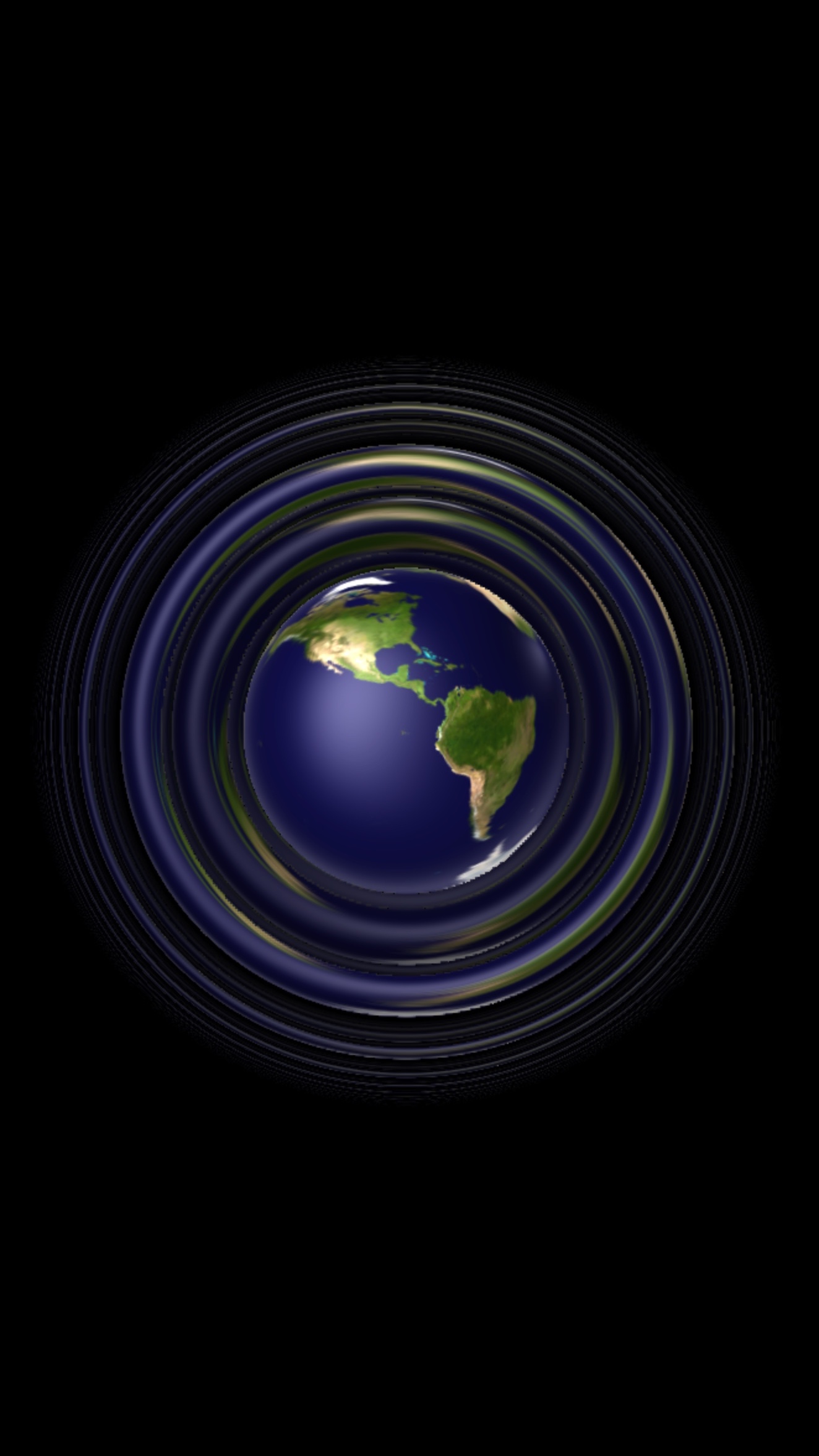
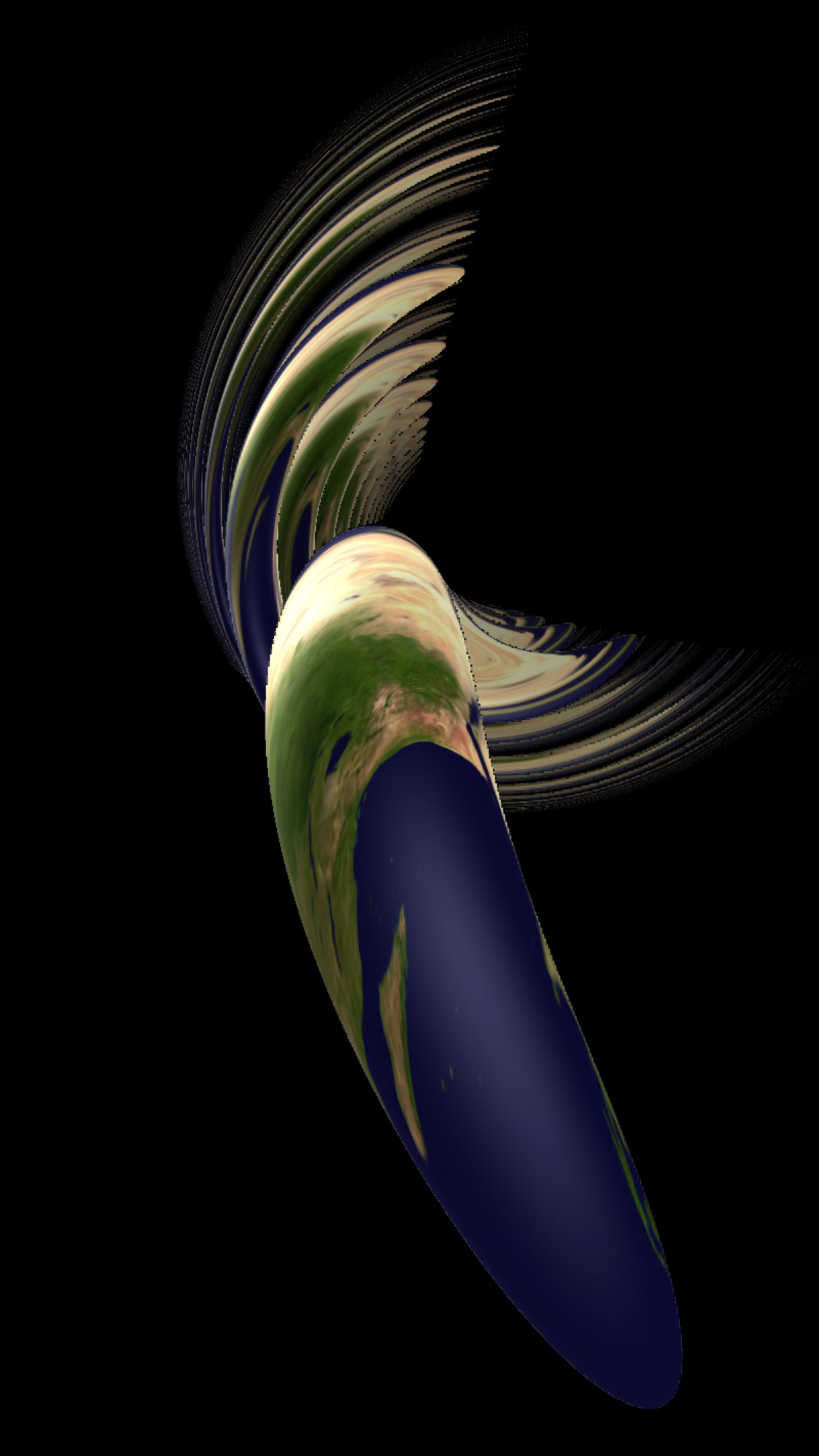
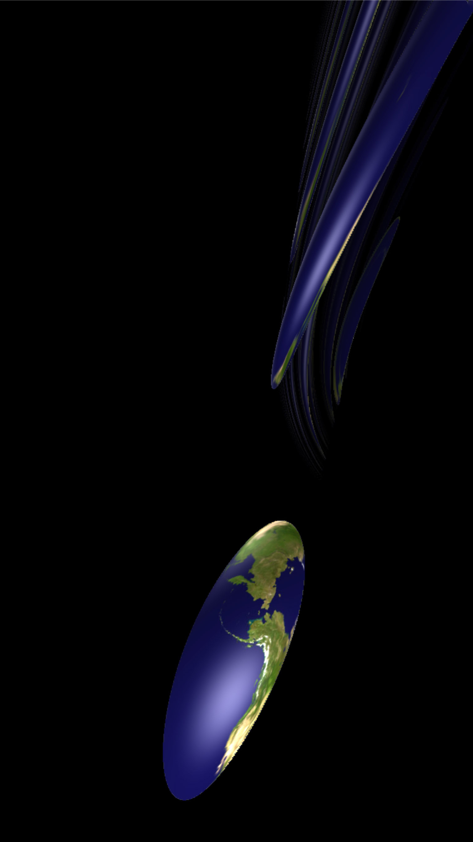
10.7. Creeping to horizontal half-spaces
As for Nil in Section 9.7, we can use a version of creeping to draw pictures of “horizontal” half-spaces. For example, in Figure 10.5 we draw the half-space , the boundary patterned with equidistant curves to a geodesic (in white).
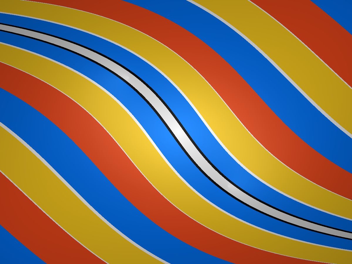
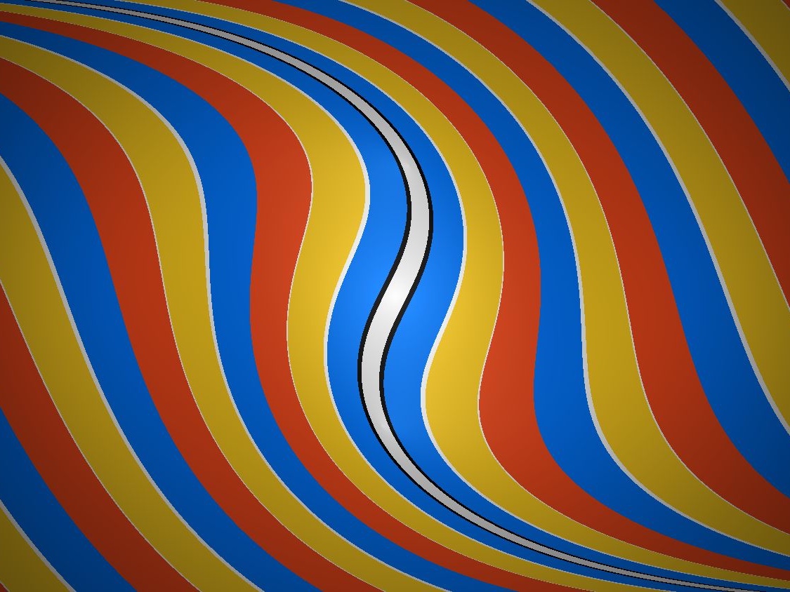
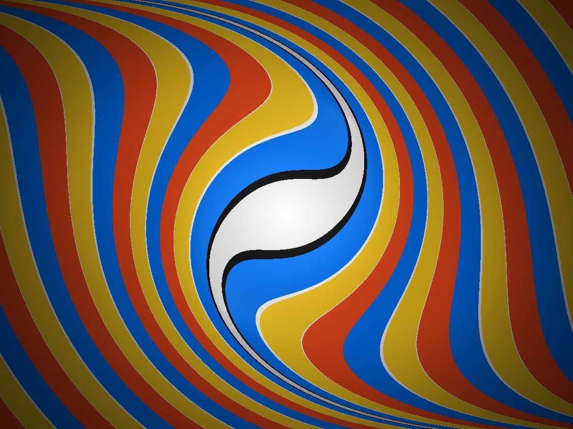
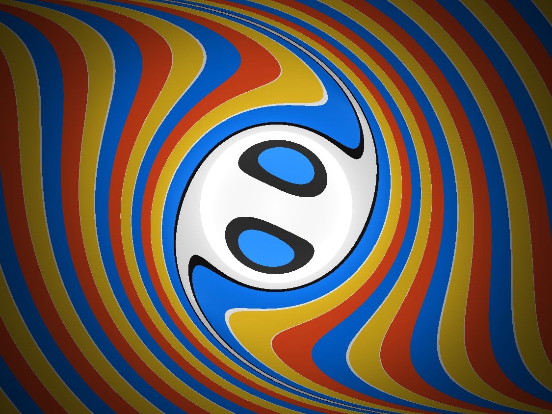
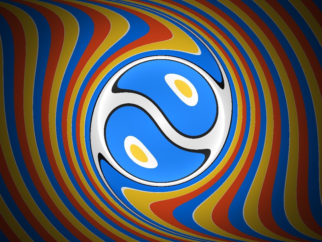
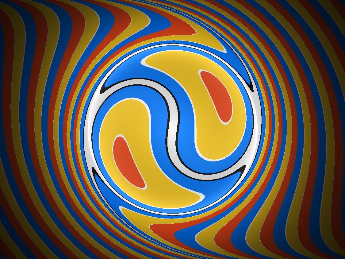
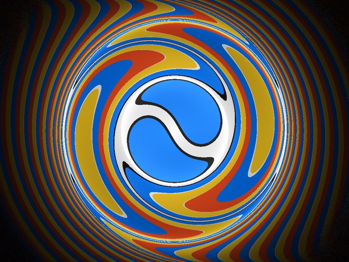
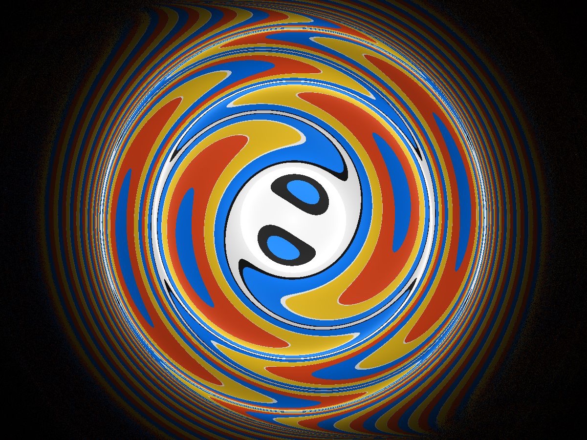
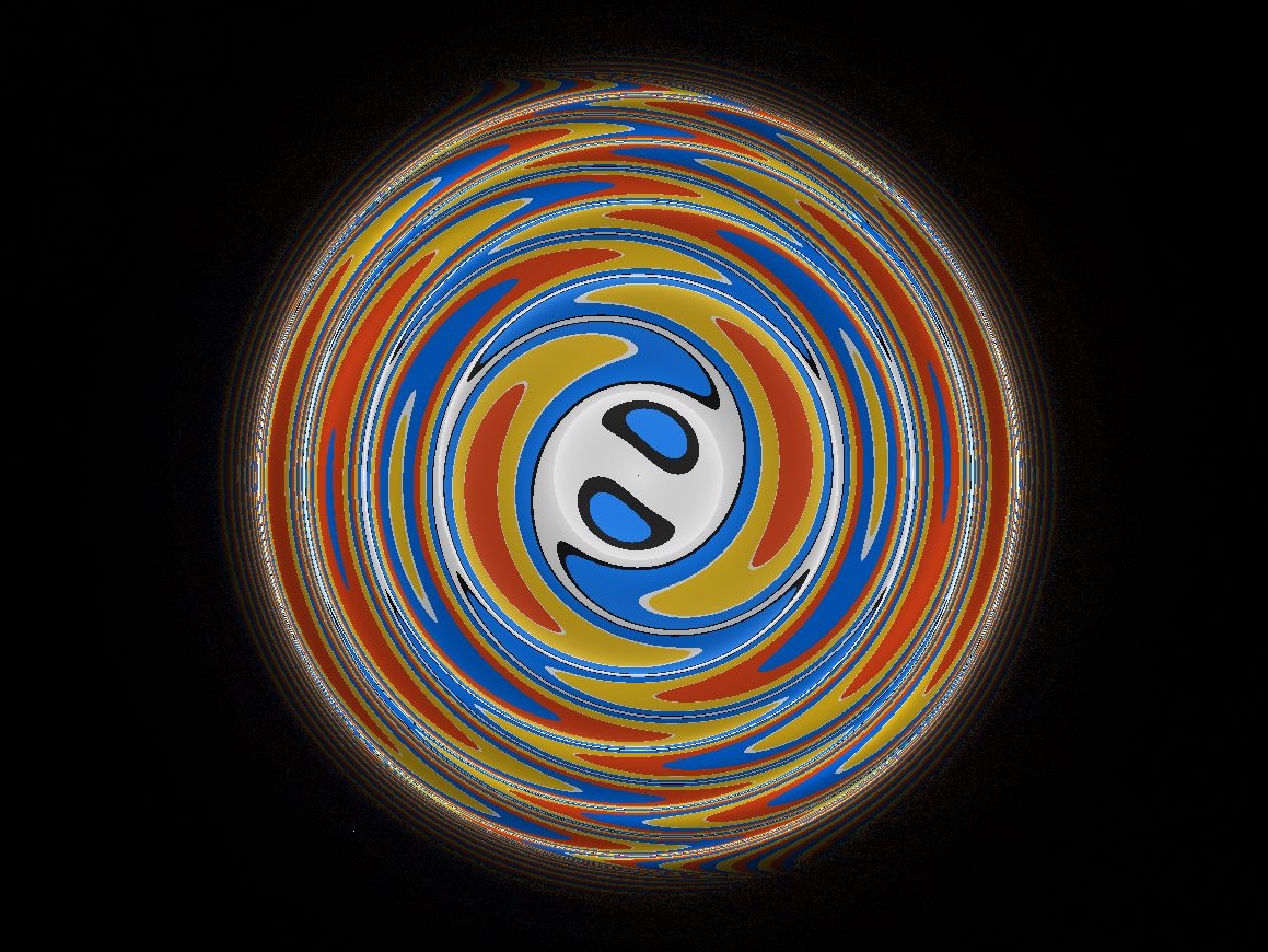
10.8. Lighting
We addressed the computation of lighting pairs in Section 10.5. Here, we calculate the intensity experienced from an isotropic light source at distance and in the direction . By Equation (5.7), this is inversely proportional to the area density . We calculate this directly by taking the derivative of the geodesic flow as in Equation (5.9).
As a first simplification, note that as the covering map is a local isometry and is a local quantity, we may treat as an identification and work directly in . Let be the unit vector expressed in the basis . Recall that Equation (10.2) gives a parameterization of the unit speed geodesic in direction as the product of two one-parameter subgroups of followed by a rotation of angle about the fiber direction. These one-parameter subgroups, and hence the geodesic flow, come in three regimes determined by whether is greater than, equal to, or less than one. Below we concern ourselves with the two generic cases.
Let be the cylindrical coordinates on with the norm of the projections onto the -plane and -axis respectively, and measured from the positive -axis. In these coordinates, the point is expressed as . Using Equation (5.13), we may calculate the area density in terms of the , and derivatives of the geodesic flow. Here one may deal with the two regimes (in these coordinates, and ) separately, or unify them into a single computation with complex trigonometric functions. This follows from the particularly nice form of the one-parameter subgroups in Equation (10.2). In either case, even after much simplification, the resulting formula for area density is rather complicated. We describe it below.
Let and let denote the polynomials in and :
To combine the two regimes, we let denote when , and for . Finally, let and be the functions
where the in is positive for and negative when . With this notation, the area density is given by
| (10.6) |
See Figure 10.6. As with the computation of the geodesic flow in Section 10.2, one should use the asymptotic expansion of Equation (10.6) to obtain correct lighting along the null cone .
Figure 10.6 shows the intensity variation, as seen in the tangent space to a point.
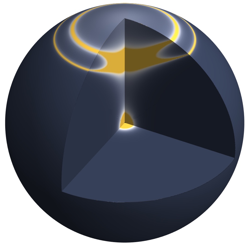
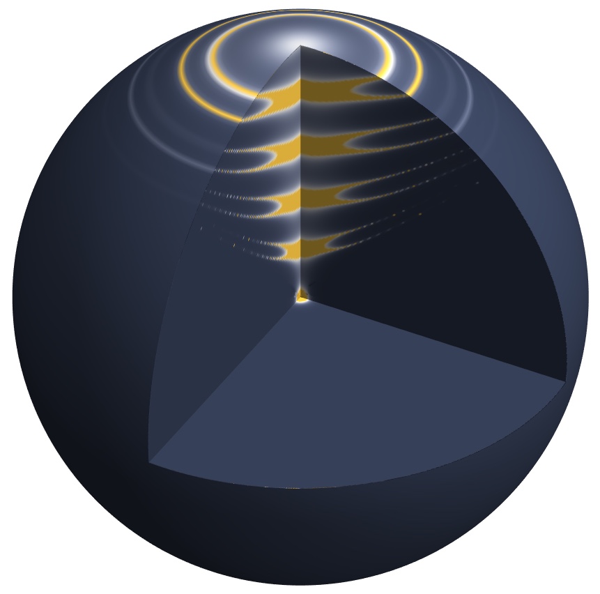
10.9. Discrete subgroups and fundamental domains.
The manifolds with geometry are classified in [Sco83, Theorem 4.15]. The main examples are unit tangent bundles of hyperbolic surfaces and two-dimensional orbifolds.
Our model of is a projective model, in the sense that it induces a faithful representation . This is not the case for however. Nevertheless, we can adapt the strategy described in Section 4.1.2 to produce an efficient fundamental domain. We explain this strategy with an example.
Let be the fundamental group of a genus two surface :
A choice of hyperbolic metric on induces a representation . For our example, we choose this metric so that a fundamental domain for the action of on is a regular octagon centered at the origin, see Figure 10.7. The generators of can now be written as points of :
2pt \pinlabel at 74 141 \pinlabel at 129 71 \pinlabel at 150 105 \pinlabel at 60 99
at 198 96 \pinlabel at 179 163 \pinlabel at 116 197 \pinlabel at 30 163

The pre-image of by the covering map is now a lattice in , viewed as a subset of , the isometries of . We choose lifts , , , and of the previous generators so that their fiber components are respectively , , , and . For convenience, we define a new element that is the translation by along the fiber direction. One checks that in . Note also that commutes with , , , and . A fundamental domain for the action of on is the subset of . However, our model is not well suited to checking easily whether a point belongs to or not.
To solve this problem, we consider the isometry between the hyperboloid model and the Klein model of . The isometry extends to a bijection
This provides yet another model for . The image of under this identification is where is now an octagon in whose sides are straight lines. We define the following normal vectors in
see Figure 10.7. To each index we associate two half-spaces
where is the standard dot product in and . We choose so that is the intersection of these half-spaces. Similarly, we let
The teleporting algorithm has two main steps. Let be a point in our new model of .
-
(1)
If does not belong to (respectively , , , , , , ), then we move by (respectively , , , , , , ). Observe that is also a Dirichlet domain for the action of on . More precisely, is the set of points in which are closer to the origin than their translates by . Hence the translation by moves the projection of to closer to . It follows that after finitely many steps, we can ensure that belongs to . Since we always reduce the distance from to , the order in which we perform the algorithm does not matter.
-
(2)
Once this is done, if does not belong to (respectively ), then we move it by (respectively ). Note that does not affect the horizontal component of . Therefore, after this process lies in the fundamental domain .
Figure 10.8 shows some views within the unit tangent bundle to a genus two surface, as described in this section. The fundamental domain is a very tall octagonal prism. To better illustrate the geometry, our scene is the complement of three spheres stacked vertically within this domain.
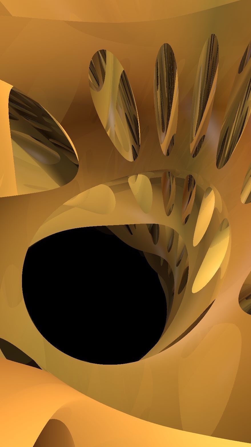
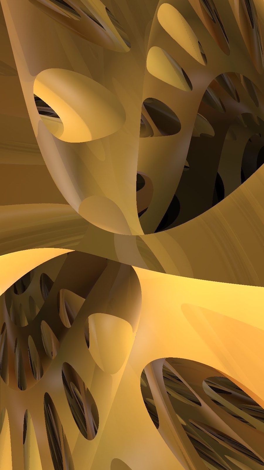
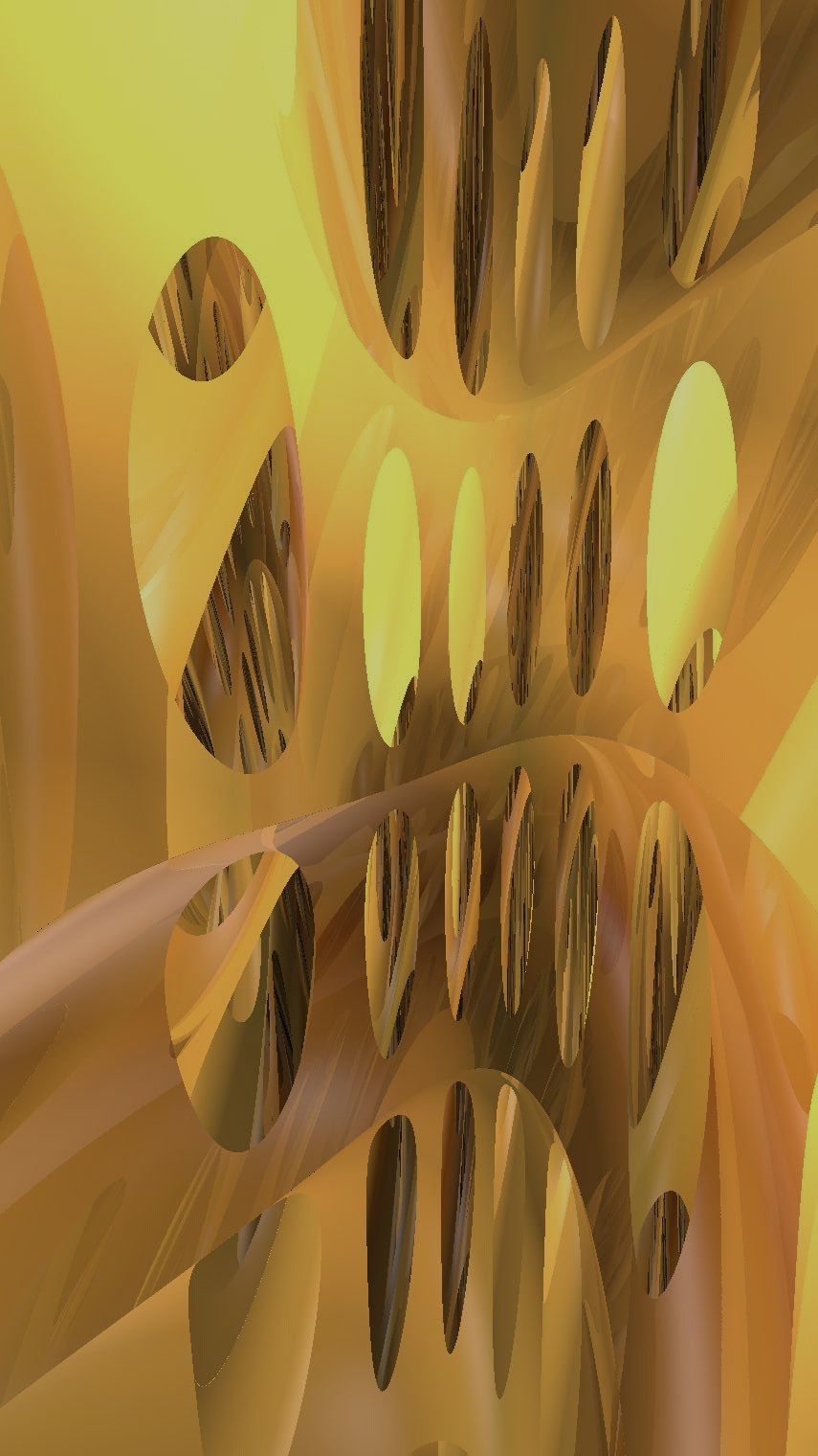
In Figure 10.9, we show the in-space view for various scenes in geometry. Figure 10.9a shows the same scene as Figure 10.8, with a globe added at the center of each of the three spheres. Figure 10.9b shows a lattice of globes in the unit tangent bundle for a sphere with cone points and . Figure 10.9c shows solid cylinders (which we implement as vertical objects) around fibers of . The lighting in these images is based on a continuously varying direction field rather than point light sources.
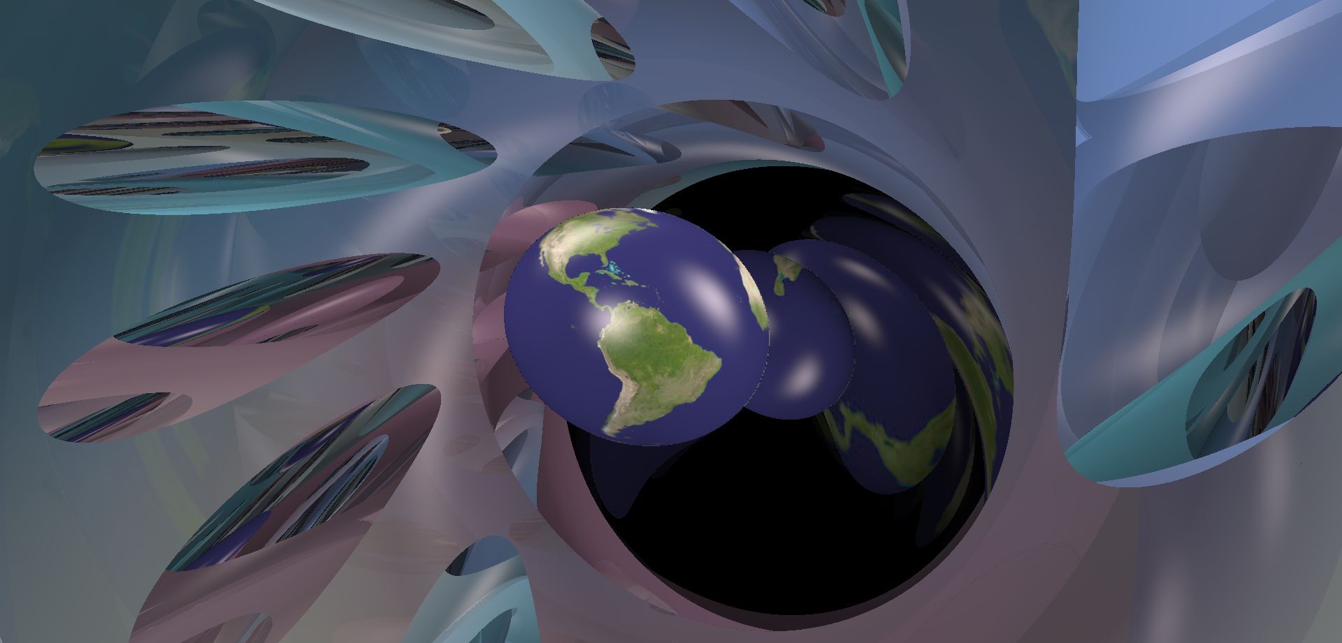
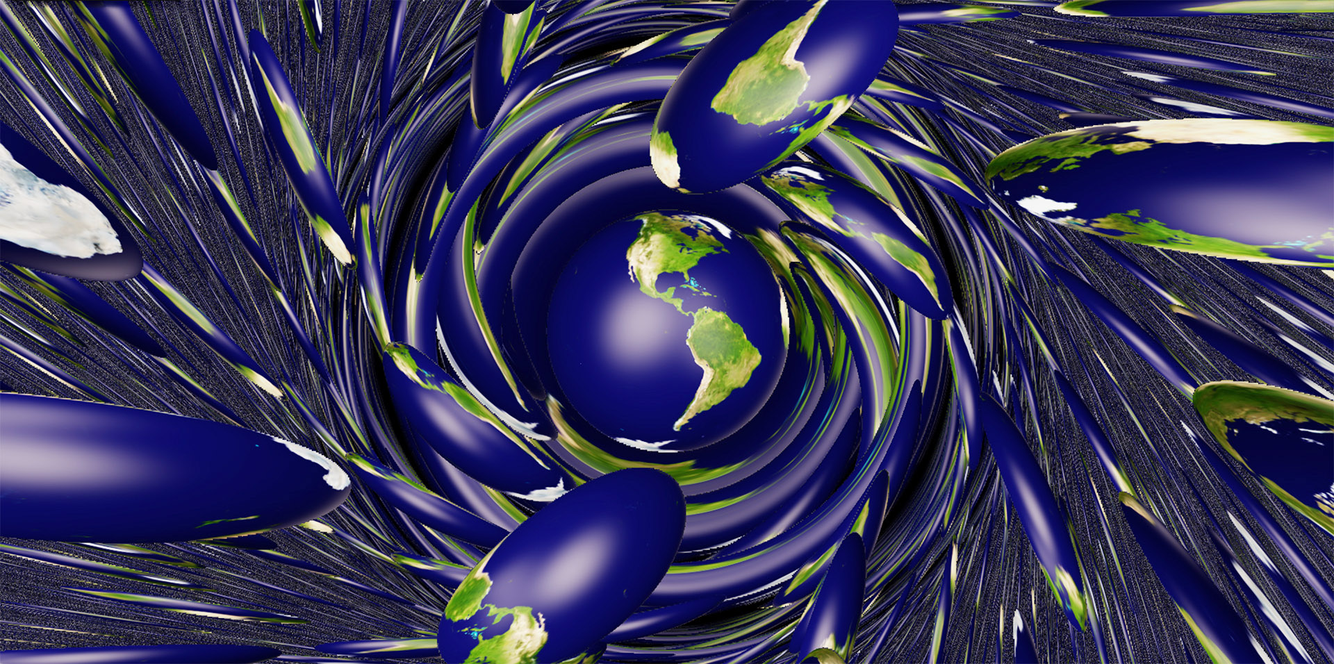
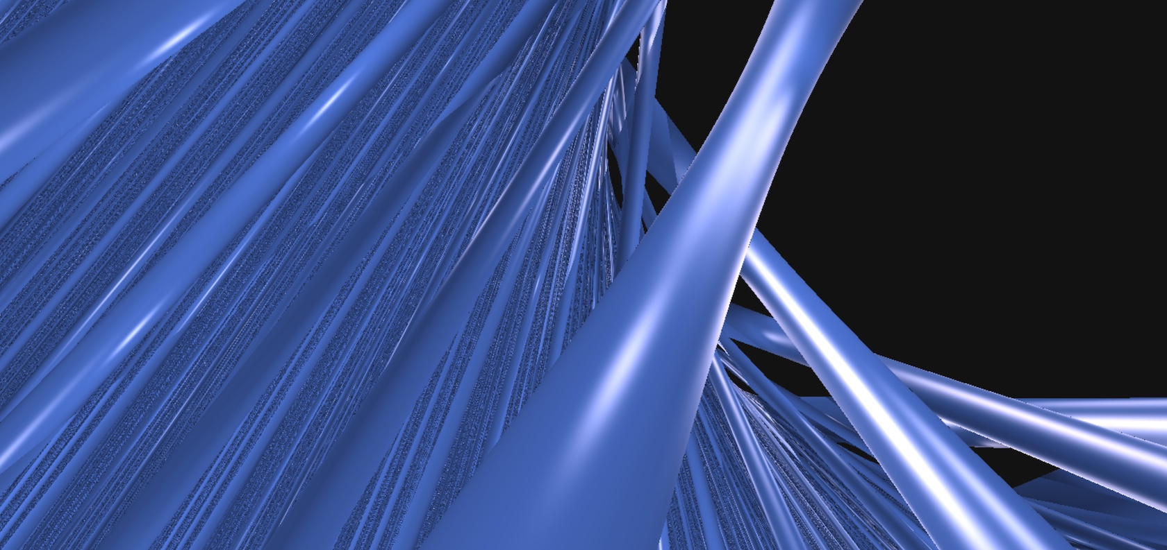
11. Sol
11.1. Model
As with Nil and , Sol is a Lie group. The underlying space of our model is the affine subspace of defined by . The group law is as follows: the point acts on on the left as the matrix
The origin is the point . Its tangent space is identified with the linear subspace of given by the equation . The metric tensor at an arbitrary point is
| (11.1) |
With this metric, the action of Sol on itself is an action by isometries. The stabilizer of the origin is isomorphic to the dihedral group of order eight, , which is generated by two symmetries acting on as the matrices
respectively. These symmetries can be observed in the balls of Sol, see Figure 11.1.

11.2. Geodesic flow and parallel transport
As for Nil and in Sections 9.3 and 10.2, we can use Grayson’s method to study the geodesic flow and parallel transport. Let be a geodesic, and let be be the corresponding parallel-transport operator. Following Sections 3.2.1 and 3.4.1, we define two paths and by the relations
After some computation, Equations (3.2) and (3.6) respectively become
and
The path , as well as the geodesic , can be computed explicitly [Tro98].333 A commonly cited reference for solving the geodesic flow in Sol is [BS07]. However, the authors do not conduct the computation to the final stage – see their Theorem 4.1(1). Moreover, the formulas given in Theorem 4.1(2) have some errors. Assume that starts at the origin , so that the initial condition is . Because of the symmetries of Sol, we can assume without loss of generality that and . We distinguish three cases.
Case .
Here the solution for is
It follows that
In particular, stays in the plane . This plane is totally geodesic and isometric to .
Case .
Here and can be deduced from the previous case, via a conjugation by the symmetry fixing the origin. That is,
and
Note that stays in the plane , which is also a totally geodesic, isometrically embedded copy of .
Case .
We first define some auxiliary parameters. Let
The associated complete elliptic integrals of the first and second kind are respectively
We denote by and the Jacobi elliptic sine and cosine functions with elliptic modulus . We write for the delta amplitude and for the Jacobi zeta function, also with elliptic modulus . For an in-depth study of elliptic functions, we refer the reader to [Jac29, OM49, Law89]. Recall that and are -periodic. Let
We also fix such that
Setting , we now have
In order to write the solution for , we let
We finally get
In practice, we use a mixed approach, as follows.
-
•
When we need to flow for a long time (for example when all objects in the scene are very far away from the camera), then we use the explicit formula above. However, if the initial direction is close to one of the hyperbolic planes, this formula suffers from many numerical errors. This is an example of the kind of error described in Section 2.4.1(2). In this case, we replace the exact solution by its asymptotic expansion of order two.
-
•
When we need to flow for a short time, the above method again seems to suffer from significant numerical errors. This happens when during the ray-marching algorithm some object is very close, or when updating the position and facing of the observer between two frames. In this situation, we numerically integrate the geodesic flow and the parallel transport equations using the Runge–Kutta method of order two.
11.3. Distance to coordinate half-spaces
Given , we write and . Note that the boundary of these half-spaces is isometric to a euclidean plane, but is not convex as a subspace of . Recall that we write for the signed distance function for the scene .
Lemma 11.2.
Fix a real number . For every point in , we have
Proof.
Observe that the collections and are both invariant under the action of Sol on itself. Thus without loss of generality, we can assume that is the origin . Similarly, the symmetry fixes the origin and permutes and . Hence it suffices to prove the statement for . Suppose that (the other case works in the same way). The path is a geodesic starting at the origin and hitting at time . Hence we have .
Let us prove the other inequality. Consider a point and a minimizing arc length parametrized geodesic from to a point . If we write the path as , then from the metric given in Equation (11.1) we get that , because is arc length parametrized. Consequently, we have
This inequality holds for every point , hence the result. ∎
In Figure 11.2, we use these signed distance functions to draw horizontal half-spaces, patterned with square tilings.
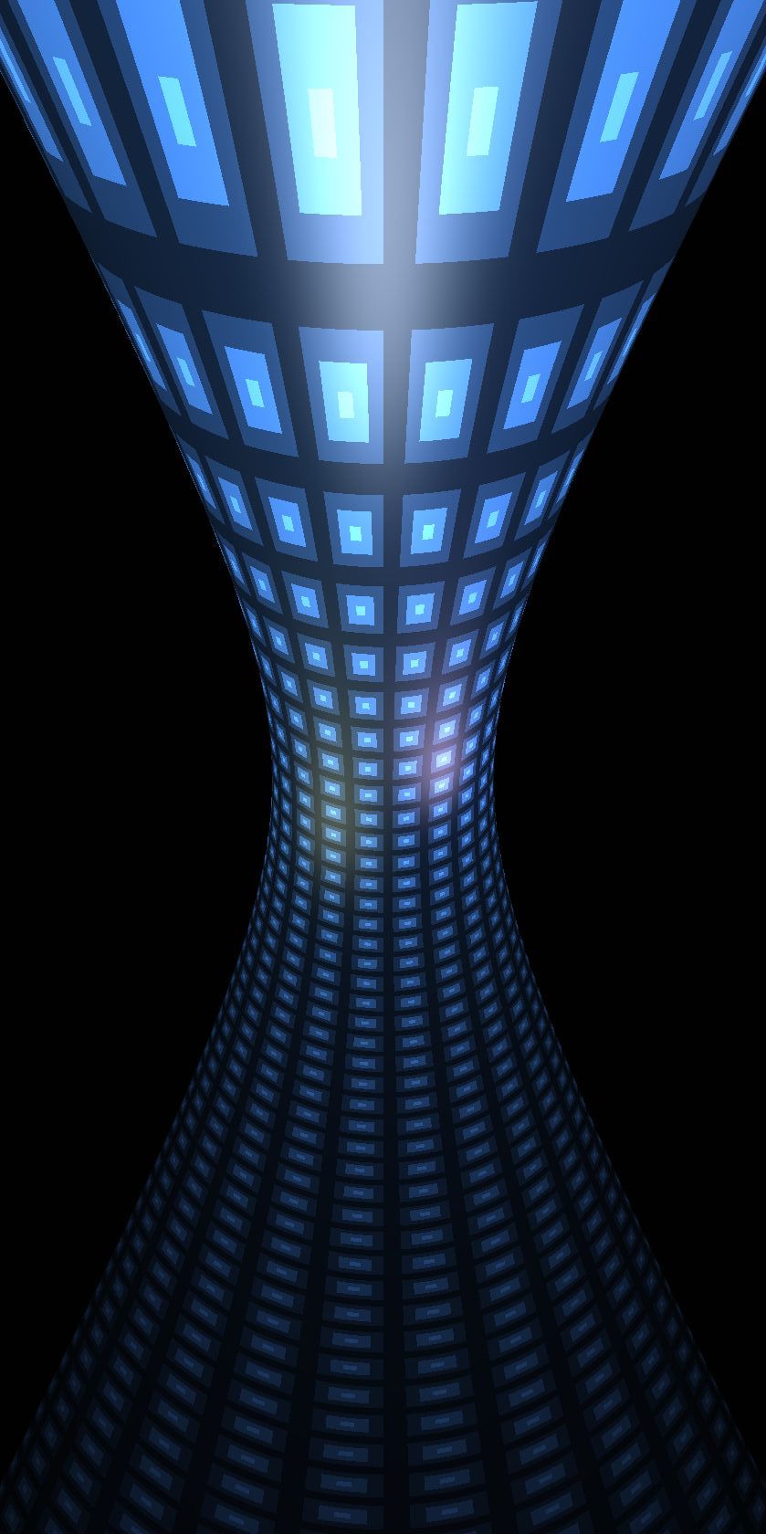
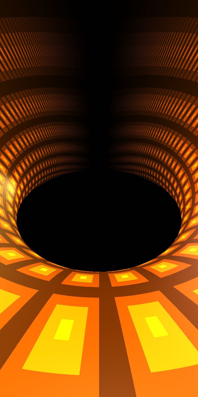
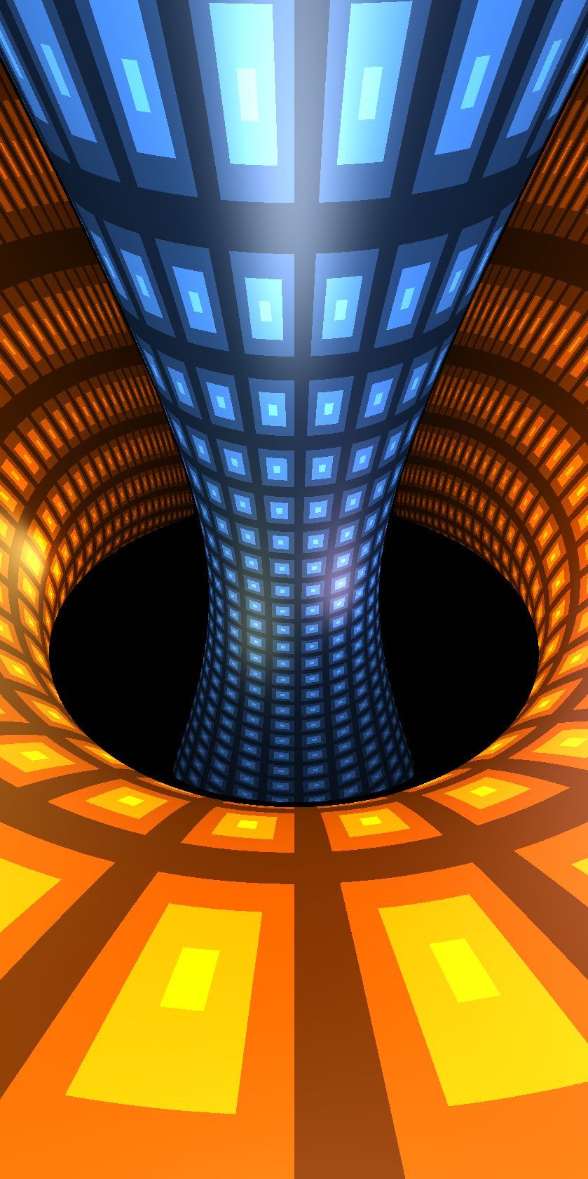
We can similarly compute the exact distance function to a half-space bounded by a hyperbolic plane in Sol. Let and .
Lemma 11.3.
Fix a real number . For every point in , we have
Proof.
Assume first that is the origin. We write the proof for with . The other cases work in the same way. We claim that the distance from to is also the distance in the hyperbolic plane from to the half plane . We have
In order to prove the converse inequality, it suffices to show that the projection sending to is -Lipschitz. To see this, take two points and , and a geodesic joining them. We write . From the metric given in Equation (11.1) we get
where and stands for the length in of and respectively. Thus, .
We now compute . Recall that is isometric to the hyperbolic plane . More precisely is a horocycle-based coordinate system of : the distance between and is characterized by
One checks that the projection of onto is the point
and
Assume now that is an arbitrary point. There is a unique element of Sol sending to . Observe that maps to where . The result then follows from the previous discussion. ∎
We can define the half-spaces as we did for . Using the fact that the isometry fixing the origin sends to we get the following statement.
Lemma 11.4.
Fix a real number . For every point in , we have
In Figure 11.3, we use these signed distance functions to draw half-spaces with hyperbolic boundary, patterned with square tilings. Combining these signed distance functions with boolean operations, we can make tubes around vertical geodesics with square cross-sections. See Figure 11.4a.
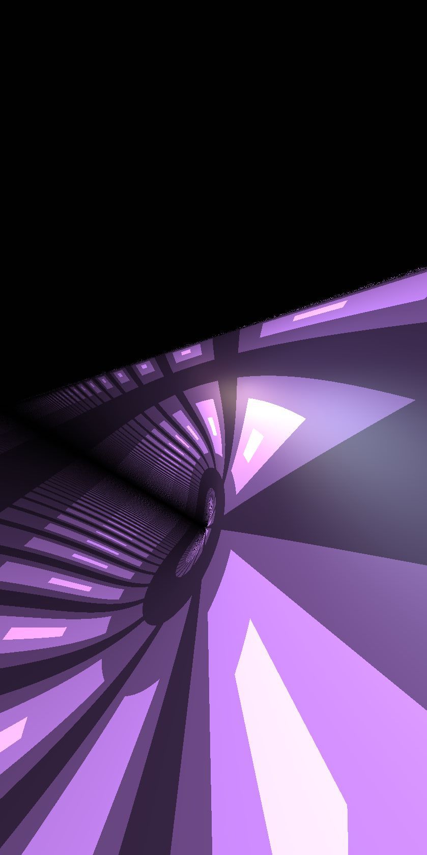
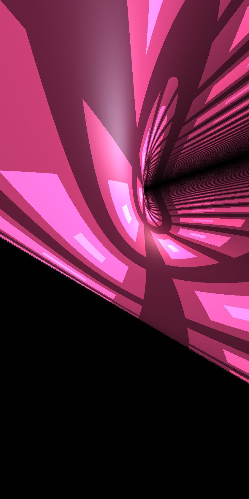
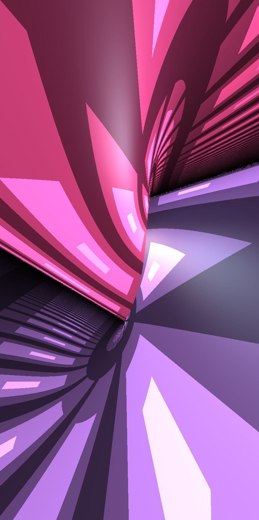
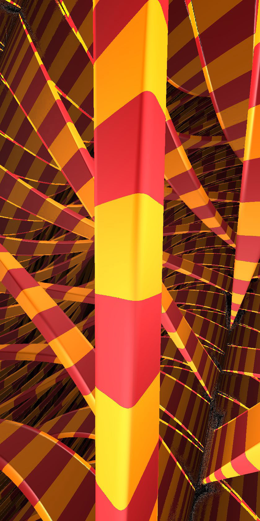
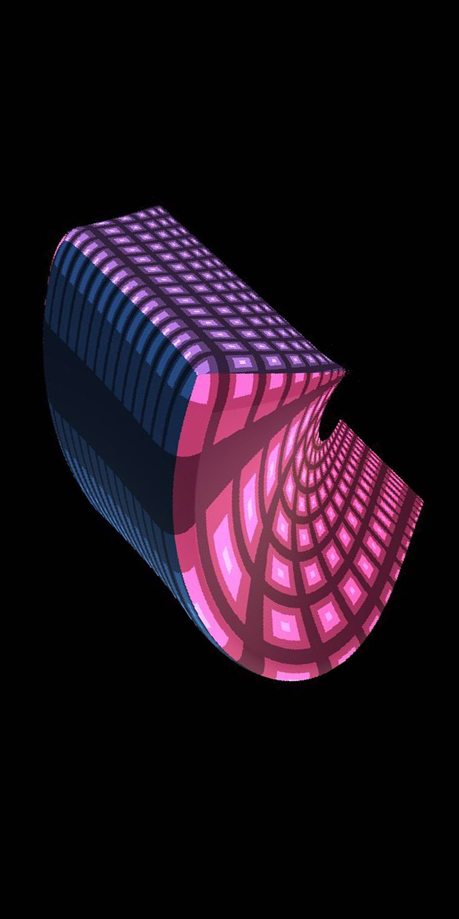
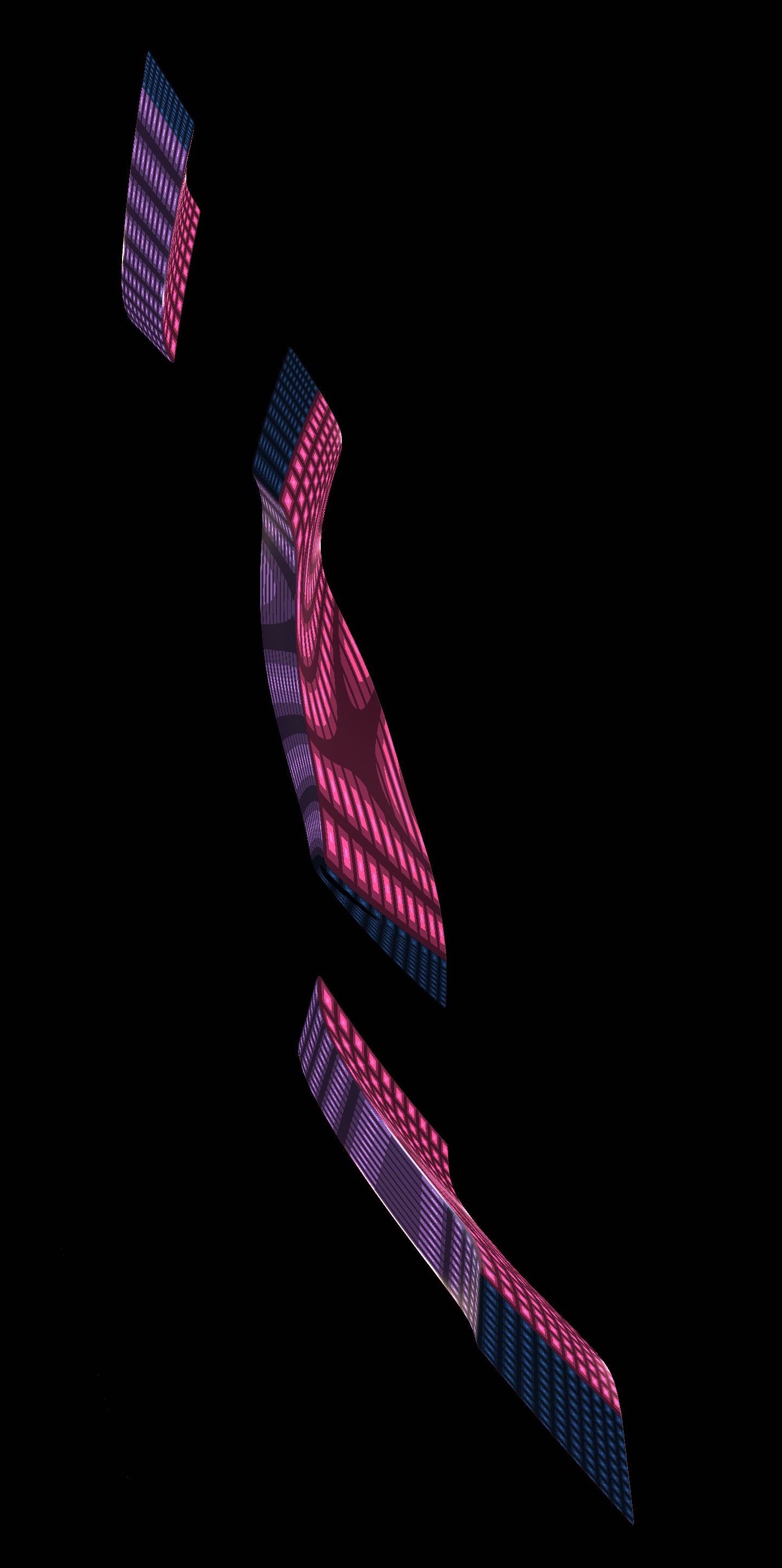
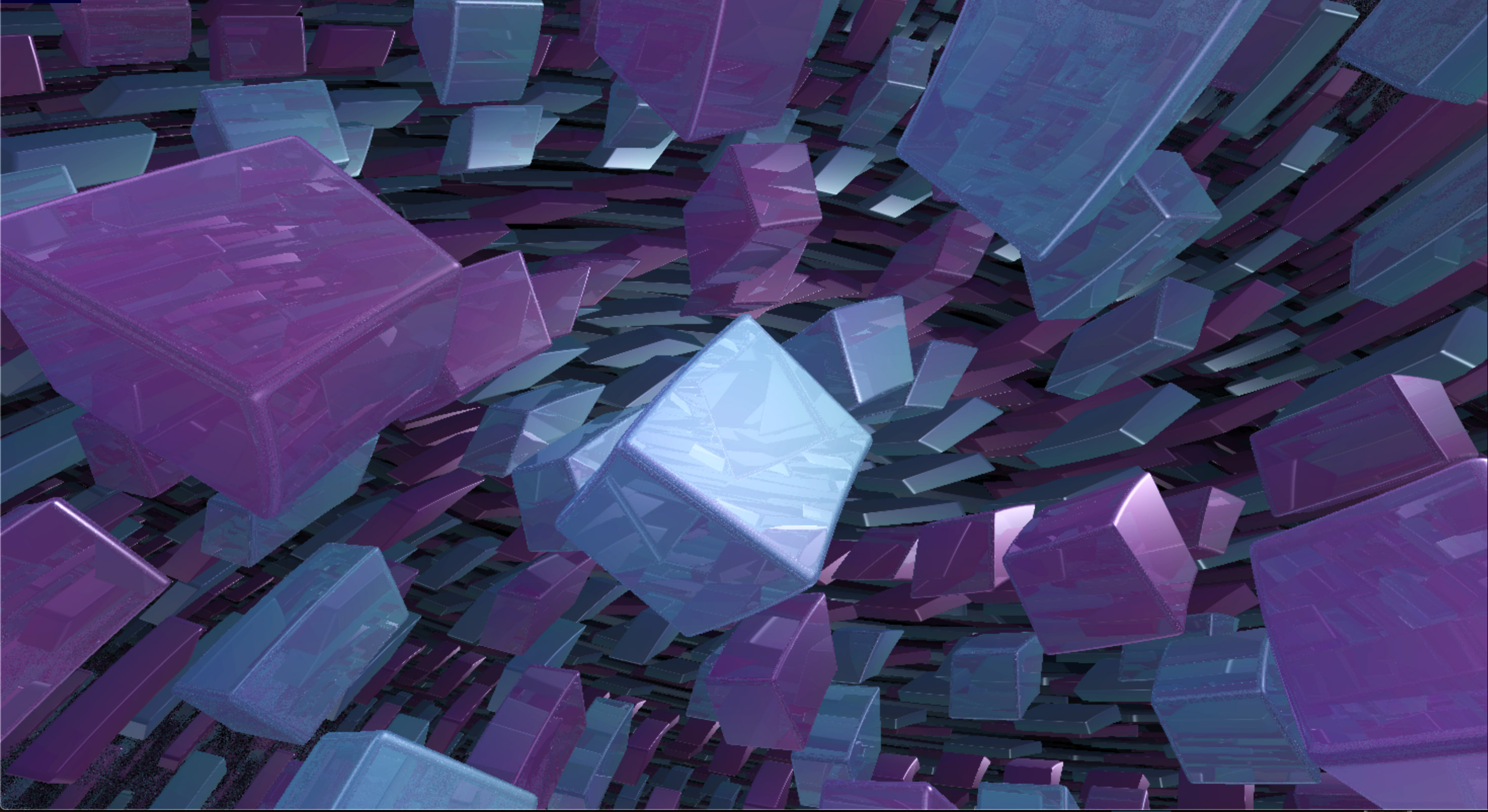
11.4. Distance to horizontal axis-aligned solid cylinders
Following the same strategy as in Section 11.3, we compute the signed distance function for certain solid cylinders. Let be the curve given by . Note that is not a geodesic of , but it is a one-parameter subgroup of Sol.
Lemma 11.5.
For every point in , we have
Proof.
Since is invariant under translations along the -axis (which are isometries of ), we can assume that has the form . Following the argument given in the proof of Lemma 11.3, we observe that . Using the distance formula in the hyperbolic plane , we get the result. ∎
Let be the solid cylinder of radius around . That is, is the set of point such that . It follows from Lemma 11.5 that the signed distance function for is
Similarly, we define the solid cylinder of radius around the curve given by . The signed distance function for is
Using the elements of Sol, we can translate the solid cylinders and to get signed distance functions for solid cylinders around any translate of the - and -axes. See Figure 11.5a.
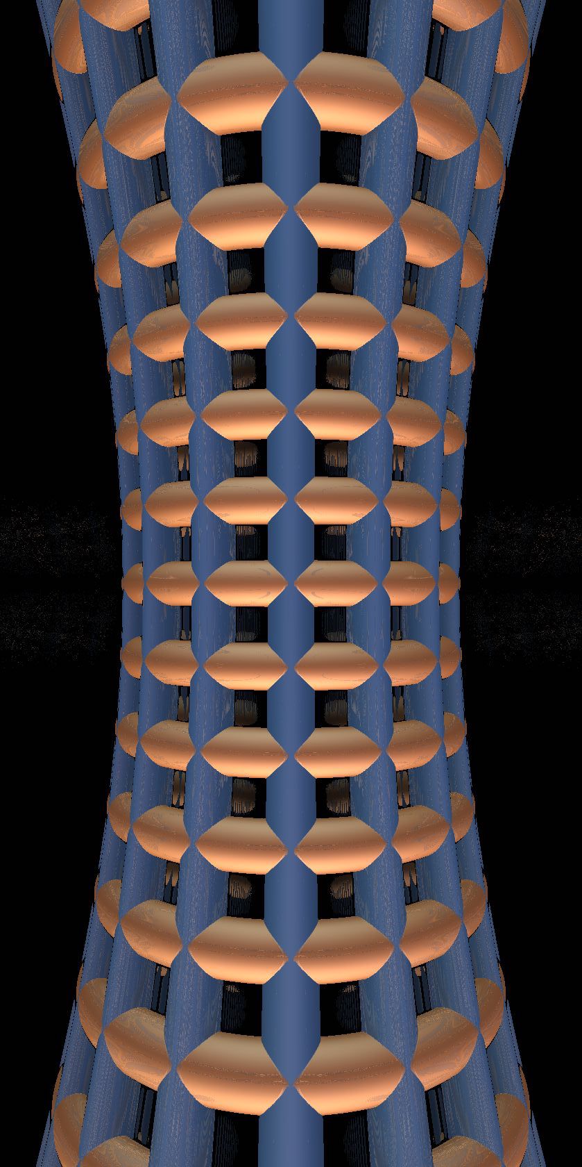
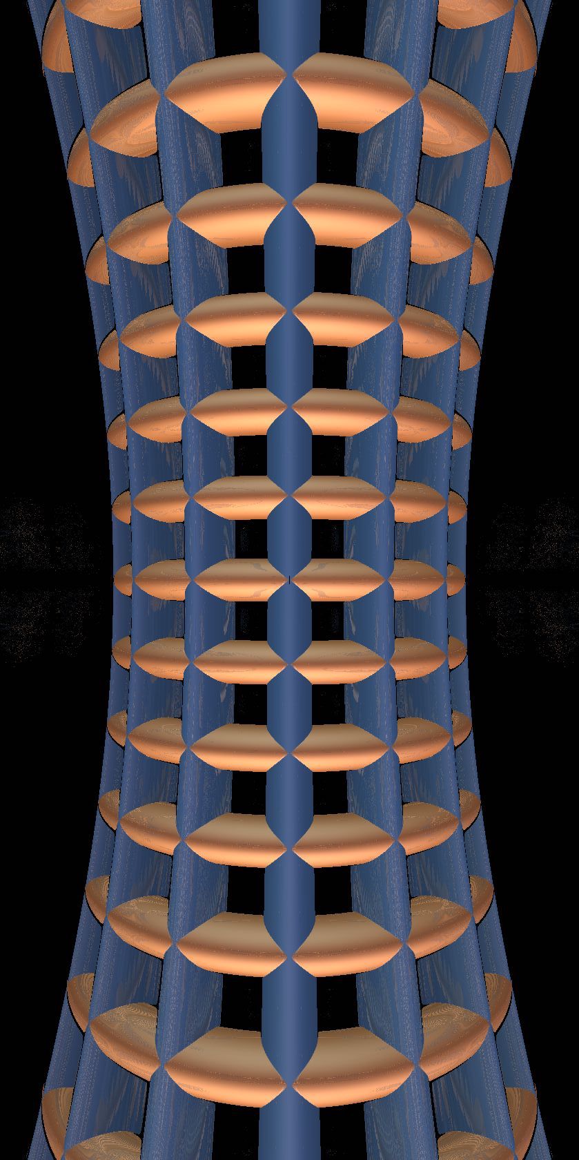
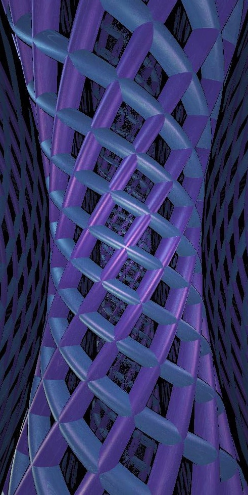
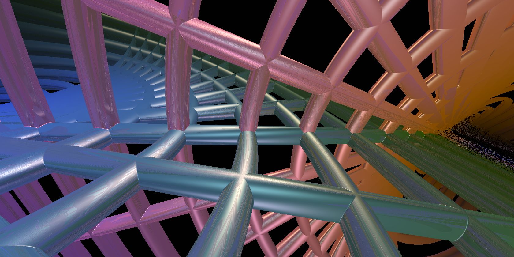
11.5. Approximating balls and more general solid cylinders
Given a point , we approximate its distance to the origin with the function
rescaled by homotheties of the domain and co-domain. This can be used to render decent “pseudo-balls”, see Figures 11.6 and 11.7b. It is not currently clear to us whether this function can be used to build a distance underestimator for correct balls.
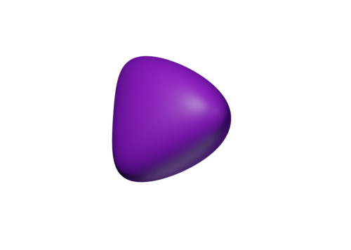
We can similarly produce “solid pseudo-cylinders,” approximating the distance from a point to an orbit of a one-parameter subgroup transverse to a plane (the horizontal plane or either hyperbolic plane). The idea is to move a point under the one-parameter subgroup to put it in the plane, and then calculate a signed distance function there. If distances are difficult to calculate (either theoretically or practically) even when restricted to the plane, then we can cheat further by measuring, say, euclidean distance in the model space.
Figure 11.5b shows solid pseudo-cylinders around the translates of the - and -axes. This compares well with the exact solid cylinders shown in Figure 11.5a. In Figure 11.5c we draw solid pseudo-cylinders around the geodesics and their translates. Note that these are the only geodesics contained in the -plane. In Figure 11.5d we reproduce the two hyperbolic planes of Figure 11.3, represented by grids of solid cylinders. The horocycles in each grid are drawn with exact signed distance functions; for the geodesics we use solid pseudo-cylinders.
11.6. Direction to a point
Although it is certainly possible to do so, we did not try to numerically compute the exact direction of geodesics joining two given points in Sol. Recall that this data is only needed to compute lighting pairs for physically correct illumination as in Section 5. As we explained in Section 5.9, we choose instead a more-or-less arbitrary, continuously varying direction field: if is a point of the scene and is the position of the light, then we run all the computations in the Phong model as if the direction from to were given by the straight line between and in the ambient space containing our model .
11.7. Discrete subgroups and fundamental domains
The classification of Sol manifolds is given in [Sco83, Theorem 4.17]. Every Sol manifold is a surface bundle over a one-dimensional orbifold. In particular, Sol can be seen as the universal cover of the suspension of a regular two-torus by an Anosov homeomorphism.
The fundamental group of provides a lattice in . We explain here with a concrete example how to construct a fundamental domain for the action of on .
To avoid any confusion, we denote by the coordinates of a point in the universal cover of the two-torus . The fundamental group acts on by integer translations. Let be the Anosov homeomorphism of acting on as the matrix
Let be the mapping torus of with monodromy . Its fundamental group is given by the presentation
Here and are the standard generators of , while the conjugation by is the automorphism of induced by . As in Nil, is generated by and . Nevertheless, is it more convenient to keep three generators, as they correspond to translations in three independent directions.
We identify the universal cover of with , equipped with coordinates . Here the set corresponds to a copy of inside . The generators and act by translation along and , while translates along and applies to the orthogonal plane.
The next step is to identify with . Let be the point of Sol whose coordinates in are . (The value of will be determined later.) We require that under our identification, the translation by in becomes the action of on . Observe that dilates the -axis while contracting the -axis. Thus we need to identify the -direction (respectively -direction) of with the expanding (respectively contracting) direction of .
The matrix defining has two eigenvalues, namely and , where is the golden ratio. The corresponding eigenvectors are
We now define a homeomorphism as the restriction to of the linear map given by the matrix
where we now set . In addition, we write and for the elements of Sol whose coordinates in are
It follows from our construction that the map conjugates the translation by (respectively , ) in to the action of (respectively , ) on . A fundamental domain for the action of on is the image under of the cube . That is,
Our model for Sol is also a projective model. The fundamental domain can be seen as the intersection of a collection of half-spaces , , as described in Section 4.1.2. Here
The half-spaces , are defined in a similar way. The teleporting algorithm has two main steps. Let be a point in .
-
(1)
If does not belong to (respectively ), then we move it by (respectively ). After finitely many steps, the new point lies in .
-
(2)
Once this is done, if does not belong to (respectively , , ), then we translate it by (respectively , , ). Note that this does not change the -coordinate of . Since and commute, we don’t pay attention to the order in which we perform these operations. After finitely many steps, the new point belongs to .
In Figure 11.7a, we draw a lattice of cubes in a neighborhood of the -plane. The center of each cube is at a vertex of the tiling of the plane corresponding to the action of the subgroup of generated by and . Figure 11.7b shows the inside view of an Anosov torus bundle, with a ball textured as the Earth for the scene. Figure 11.7c shows the same manifold, with the complement of three solid pseudo-cylinders around the curves , , and as the scene.
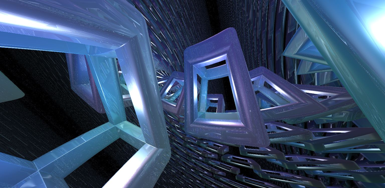
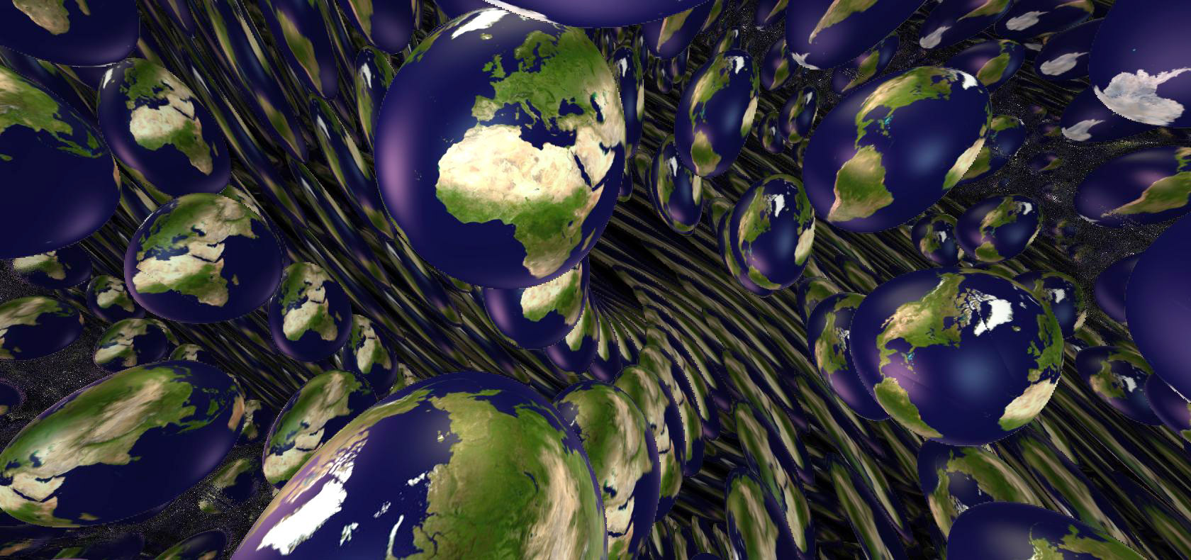
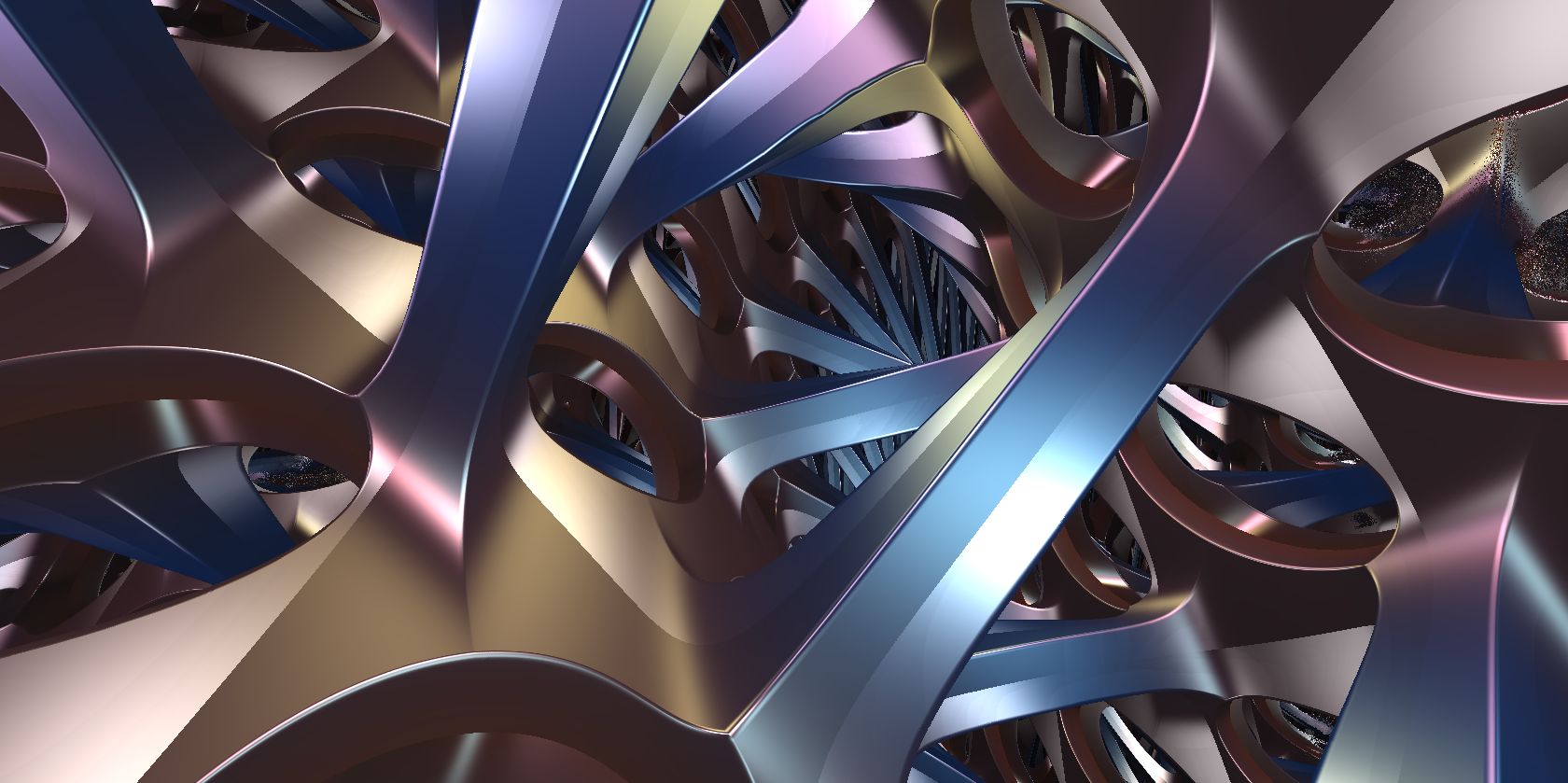
12. Future directions
12.1. Virtual reality
As mentioned in Section 3.6, there are serious problems that must be addressed before we can use stereoscopic vision to give the user depth cues in a virtual reality experience.
12.2. Sol
Some elements of our work are still incomplete for Sol geometry, namely correct lighting, and correct signed distance functions (or even distance underestimators) for balls. One of the difficulties is that we do not yet have an efficient method to compute the lengths and directions of the geodesics from the origin to an arbitrary point .
For Nil and , we used the rotation-invariance of our model to build a one-to-one correspondence between those geodesics and the zeros of a function (depending on ), see Sections 9.5 and 10.5. Since is convex on each interval where it is defined, Newton’s method very efficiently computes its zeros. In particular, any value where can serve as a seed for the algorithm.
The lack of rotation invariance in Sol makes it much harder to implement similar ideas. One could use a multi-variable Newton’s method to find the geodesics from to . It is however not obvious where to start the procedure. A deeper analysis of the solutions of the geodesic flow is needed here.
12.3. Directed distance underestimators
For certain scenes it can be difficult to produce the corresponding signed distance function, or even a distance underestimator. An example is the -plane in the Nil geometry (Section 9.7). However, when we are ray-marching along a geodesic , we do not in fact need to know the distance from any point to the scene, but only the distance to the closest point of the scene lying on . This leads us to the following definitions.
Definition 12.1.
Given a scene , the associated directed signed distance function is a map characterized as follows. Let be a tangent vector at . Let be the geodesic starting at in the direction .
-
•
If does not belong to , then is the distance from to the closest point of on .
-
•
If is in , then is the distance from to the closest point of on . ∎
Such a function is a priori also very hard to obtain. Indeed it means that we can compute the intersection of any geodesic with our scene; this is precisely the data required for ray-tracing. Nevertheless, as in Section 2.2, we can perform ray-marching using an underestimator that takes as its input a tangent vector to a ray.
Definition 12.2.
A directed distance underestimator for the scene is a map such that
-
(1)
The signs of and are the same for all points ,
-
(2)
for all , and
-
(3)
If is a sequence of points in such that converges to zero, then so does . ∎
Ray-marching with such a directed distance underestimator will produce the same pictures as ray-marching with an undirected signed distance function. These, in some sense, bridge the gap between ray-tracing and undirected ray-marching. With directed distance underestimators, we expect to expand the collection of scenes that we can render.
Directed distance underestimators may also help improve efficiency. When using a standard signed distance function (or distance underestimator), the length of the steps becomes very small as a geodesic ray passes very close to the scene without hitting it. If the maximal number of steps for the algorithm is not large enough, this creates background-colored halos around objects. With a directed distance underestimator, we can hope that the length of the steps in this situation will be larger, thus making the algorithm converge faster.
12.4. Non-maximal homogeneous riemannian geometries
Recall that the transitive action of a Lie group on a manifold determines a homogeneous geometry. To be a Thurston geometry, a homogeneous geometry must satisfy four additional restrictions, see Section 1.1. The first two of these conditions, having simply connected and act with compact point stabilizer, define a riemannian homogeneous space. (For a complete classification of three-dimensional riemannian homogeneous spaces, see [Pat96].) These two conditions greatly simplify calculations of the geodesic flow, parallel transport, and more. The second two conditions restrict to those needed for geometrization. However, we do not need these conditions anywhere in our ray-marching algorithms. There are many interesting geometries satisfying only the first two conditions that could be visualized in a similar fashion. Celińska-Kopczyńska and Kopczyński have begun to investigate visualizations of one-parameter spaces of metrics of this kind on the three-sphere.
12.5. Homogeneous pseudo-riemannian & lorentzian geometries
Generalizing riemannian geometry, a pseudo-riemannian manifold is a manifold together with a choice of (not necessarily positive definite) nondegenerate bilinear form on each tangent space. When the bilinear form is not positive definite, the existence of null vectors (nonzero with ) makes these spaces difficult to interpret visually (although see [Ega17] for a literary interpretation). However, there is one class of pseudo-riemannian manifolds for which there is a clear interpretation of what the intrinsic view looks like: lorentzian manifolds. These have bilinear forms of signature and are the basic models of space-time in relativistic physics.
In relativity, light travels along the null geodesics (geodesics with null tangents) in a lorentzian manifold, and so the intrinsic view may be computed by ray-marching starting with the lightcone of null vectors in the tangent space of the viewer. In the real world, we see light that travels along null geodesics in a lorentzian four-manifold. Arguably, then, it is more natural to consider the inside view of a lorentzian four-manifold rather than of a riemannian three-manifold.
The natural starting place is flat space-time: the Minkowski space . Ray-marching along lightcones in this geometry provides a method of simulating the inside view in special relativity. Previous visualization work in special relativity includes [SSM07, MWM+10, MGW10, SCTK16]. Generalizing to homogeneous space-times of constant curvature, one could produce intrinsic simulations of de Sitter and anti-de Sitter space-time. Many of the methods described in Section 3 can be adapted to this setting. All three of these have natural projective models in , and explicit descriptions for their null geodesics and isometry groups are well known (see for example, [Sok16] and [KOP02]).
Beyond these, the classification of general lorentzian homogenous four-manifolds has been completed [CZ14], although it is more complex than the case of riemannian three-manifolds discussed above. In all such manifolds we may use analogs of the techniques introduced in Section 3 to simplify computations.
12.6. Non homogeneous geometries
Giving up on symmetry, there are many non-homogeneous riemannian and lorentzian manifolds for which intrinsic views may prove useful. Examples include watching a three-manifold evolve under the Ricci flow, analyzing collapsing space-times, or space-times with singularities (black holes). In most cases, the lack of symmetry forces us to use numeric solutions for the geodesic flow. However, there are also interesting non-homogeneous spaces with exactly solvable geodesic flow. These include the matrix group with the metric it inherits from the matrices as a hypersurface. However, these spaces all present considerable difficulties for the methods outlined in Section 3, and will require more work.
Appendix A Comparison between methods to integrate the geodesic flow
In this work, whenever possible we have avoided numerical methods for following geodesics and have instead exploited explicit solutions of the geodesic flow. This allows us to quickly and accurately ray-march long distances, and thus render scenes with distant objects [CMST20a, CMST20b]. To support our choice, we ran some numerical experiments. We explain our protocol below.
Remark A.1.
We do not claim to give a comprehensive and rigorous comparison of the various methods to integrate the geodesic flow. The computations here are made in Python (using Numpy long double floats) on a standard desktop computer. We do not use the GPU, and no parallel computing is involved. Nevertheless, we can use these experiments to compare the relative efficiency of the algorithms. ∎
A.1. Experimental protocol
Let be one of the Thurston geometries. We fix an integer and a time . We compare four methods: using exact formulas, Euler’s method, and the Runge–Kutta methods of order two and four. For the numerical methods, we also compare different step sizes .
We first generate a list of unit tangent vectors at the origin , chosen uniformly and independently at random. For each experiment in each of the Tables 7, 8, 9, and 10, we fix a method and (for the numerical methods) a time-step. We then do the following computations.
-
•
For each direction , we flow from for time and record the final position. This yields a list of points. We also record the time needed to compute .
-
•
Next, for each , we measure the error of with respect to the exact flow. We discuss our choice of error measurements in Section A.2.
-
•
Finally, we compute the maximal and mean errors for the set .
A.2. Measuring errors
We calculate two different measures of error. Fixing notation, let be one element in our collection of random tangent vectors and be the point obtained by following the geodesic flow starting at in the direction of in for time in the experiment .
A.2.1. Distance error
We compute the coordinates of the point obtained by following the geodesic flow starting at in the direction of in for time using the exact formulas.
Definition A.2.
The distance error is the distance in the metric of between and . ∎
Remark A.3.
One should worry about how accurate our computer’s implementation of the exact formulas is. As mentioned in Remark A.1, we use NumPy for all of our calculations here, and long doubles, giving us around 19 decimal digits of accuracy. While we have not looked into the actual implementations of the functions we use, we would certainly hope that these implementations lose at most one or two digits of accuracy on each operation. Of course the results of these functions then need to be combined, which compounds the errors. Without using interval arithmetic, it is hard to say how accurate our final results are. However, as we will see in our experiments, with small values of and small step size , our exact calculation matches Runge–Kutta of order four () up to a distance error of around at worst. This provides evidence that our implementation of the exact formulas are at least this accurate in comparison with the true values, since the exact and Runge–Kutta methods take very different routes to their results. ∎
The distance error is natural, but the results are sometimes difficult to interpret because of our lack of intuition in those geometries. Moreover, our eyes place far more importance in which direction one sees an object in, over how far away it is. If we have an error in distance, then perhaps at worst the effect of fog is slightly incorrect. An error in direction could cause us to see objects in the wrong place, or distorted in some way. To better measure this, we introduce our second error measurement.
A.2.2. Angle error
We compute the tangent vector so that the exact geodesic flow starting from in the direction of hits the point . When there are multiple such tangent vectors , we choose the one which is closest (in angle) to .
Definition A.4.
The angle error is the angle between and . ∎
Following our goal of producing accurate images in Section 1.2, it is reasonable to require that each pixel of our screen be colored according to an object that should be visible through that pixel. Therefore, given the resolution of our screen and a desired field of view, one can calculate a maximum acceptable angle error, as follows.
[c] at 240 262 \pinlabel [c] at 414 146 \pinlabel [l] at 102 157 \pinlabel at 188 128 \pinlabel [c] at 170 105 \pinlabel [l] at 136 154 \pinlabel [l] at 142 131 \pinlabel [l] at 115 97 \pinlabel [l] at 275 96 \pinlabel [l] at 240 62 \pinlabel [br] at 253 75 \endlabellist

Let and be the locations on our screen corresponding to the directions and . See Figure A.1. Suppose that the width of the screen is one unit. The distance between and can be estimated as follows.
Assume that the field of view is . Let be the angle between and the vector pointing forwards, and let be the angle between and . Then the distance is at most
For a fixed angle error , this quantity is the largest when is on the border of the screen, that is when . Hence the worst error for is related to by
For the picture on the screen to be accurate, we need to be less than half the width of a pixel. For example, fixing the field of view at , the maximum acceptable angle error (in degrees) is
-
•
3e-02 to produce a pixel image,
-
•
6e-03 to produce a pixel image.
Set of points joined to by at least two geodesics
[l] at 650 396 \pinlabel Set of points joined to by exactly one geodesic [l] at 650 287 \pinlabel Numerical path with initial direction [l] at 650 196 \pinlabel Exact geodesic with initial direction [l] at 650 116 \pinlabel Exact (minimizing) geodesics [l] at 650 50
[c] at 225 63 \pinlabel [c] at 448 363 \pinlabel [c] at 390 254 \pinlabel [c] at 137 20 \pinlabel [c] at 305 97 \pinlabel [c] at 325 30 \endlabellist

Remark A.5.
When following the geodesic flow for a time which is smaller than the injectivity radius of the geometry , there is only one exact geodesic joining to . Here there is no choice in the definition of . For longer flow times, a new phenomenon arises. As usual, we numerically compute the path starting at in the direction and reach the point . This path approximates the exact geodesic ray starting at in the direction , which reaches the point . See Figure A.2. Suppose that multiple exact geodesics join to , so that in addition to the direction , we can also reach along a geodesic with starting direction . Suppose also that due to numerical errors, only one exact geodesic joins to . The vector is then the only possible initial direction pointing from to . It will be close to one of and , but it may be close to the wrong one: . Thus, the angle between and can be very large. However, the visual effect of this error will be indistinguishable from similar inaccuracies with the same distance error.
This situation is very rare: our numerical path must approximate a non-minimizing geodesic, with endpoint close to the boundary of one of the sets
For the Thurston geometries, these boundaries form a zero-measure set.
In our results, we indicate the number of points for which the angle between and is more than a large threshold, for example . These cases correspond to the situation described above. We compute the maximal and mean errors excluding these exceptional samples. ∎
A.3. Results.
We carried out our protocol for Nil and . We computed the distance and angle errors using the numerical methods described in Sections 9.5 and 10.5 respectively. See Tables 7, 8, 9, and 10. We made sure that the errors coming from use of Newton’s method to calculate are negligible compared to the results. We ran the experiments for time and . Note that is less than the injectivity radius ( for both Nil and ).
| Method |
Time needed (in s.) |
Maximal distance error |
Mean distance error |
Number of directions off () |
Maximal angle error (in ) |
Mean angle error (in ) |
|
|---|---|---|---|---|---|---|---|
| Exact flow | – | 0.2 | – | – | – | – | – |
| Euler | 0.1 | 12.0 | 8.4e-01 | 5.2e-01 | 0 | 8.7e+00 | 4.4e+00 |
| Euler | 0.01 | 115.3 | 8.6e-02 | 5.2e-02 | 0 | 9.4e-01 | 4.8e-01 |
| Runge–Kutta 2 | 0.1 | 17.8 | 9.3e-03 | 5.0e-03 | 0 | 1.7e-01 | 3.1e-02 |
| Runge–Kutta 2 | 0.01 | 176.0 | 9.6e-05 | 5.1e-05 | 0 | 1.7e-03 | 3.0e-04 |
| Runge–Kutta 4 | 0.1 | 32.4 | 8.2e-06 | 4.2e-06 | 0 | 8.1e-05 | 1.8e-05 |
| Runge–Kutta 4 | 0.01 | 323.3 | 8.2e-10 | 4.2e-10 | 0 | 2.7e-08 | 1.2e-09 |
| Method |
Time needed (in s.) |
Maximal distance error |
Mean distance error |
Number of directions off () |
Maximal angle error (in ) |
Mean angle error (in ) |
|
|---|---|---|---|---|---|---|---|
| Exact flow | – | 0.3 | – | – | – | – | – |
| Euler | 0.1 | 20.4 | 3.8e+00 | 2.2e+00 | 690 | 6.0e+01 | 1.4e+01 |
| Euler | 0.01 | 191.8 | 4.3e-01 | 2.2e-01 | 71 | 5.3e+01 | 2.4e+00 |
| Runge–Kutta 2 | 0.1 | 30.0 | 3.1e-02 | 1.4e-02 | 186 | 2.5e+00 | 7.5e-02 |
| Runge–Kutta 2 | 0.01 | 297.0 | 3.3e-04 | 1.4e-04 | 19 | 1.5e-01 | 9.8e-04 |
| Runge–Kutta 4 | 0.1 | 54.7 | 2.8e-05 | 1.2e-05 | 0 | 2.0e-02 | 5.7e-05 |
| Runge–Kutta 4 | 0.01 | 540.1 | 2.8e-09 | 1.2e-09 | 0 | 3.5e-06 | 4.5e-09 |
| Method |
Time needed (in s.) |
Maximal distance error |
Mean distance error |
Number of directions off () |
Maximal angle error (in ) |
Mean angle error (in ) |
|
|---|---|---|---|---|---|---|---|
| Exact flow | – | 0.8 | – | – | – | – | – |
| Euler | 0.1 | 33.2 | 3.7e+00 | 2.7e+00 | 0 | 5.2e+01 | 5.4e+00 |
| Euler | 0.01 | 325.1 | 6.6e-01 | 3.9e-01 | 0 | 2.7e+00 | 7.1e-01 |
| Runge–Kutta 2 | 0.1 | 49.0 | 4.8e-02 | 2.8e-02 | 0 | 1.0e+00 | 1.3e-01 |
| Runge–Kutta 2 | 0.01 | 485.5 | 6.6e-04 | 3.6e-04 | 0 | 9.4e-03 | 1.2e-03 |
| Runge–Kutta 4 | 0.1 | 83.9 | 4.1e-05 | 2.4e-05 | 0 | 2.0e-03 | 1.8e-04 |
| Runge–Kutta 4 | 0.01 | 817.5 | 4.7e-09 | 2.3e-09 | 0 | 1.9e-07 | 1.3e-08 |
| Method |
Time needed (in s.) |
Maximal distance error |
Mean distance error |
Number of directions off () |
Maximal angle error (in ) |
Mean angle error (in ) |
|
|---|---|---|---|---|---|---|---|
| Exact flow | – | 0.7 | – | – | – | – | – |
| Euler | 0.1 | 53.7 | 1.1e+01 | 7.9e+00 | 594 | 4.0e+01 | 8.3e+00 |
| Euler | 0.01 | 523.3 | 6.2e+00 | 3.6e+00 | 74 | 3.7e+01 | 2.2e+00 |
| Runge–Kutta 2 | 0.1 | 78.5 | 9.0e-01 | 3.3e-01 | 180 | 4.0e+01 | 5.9e-01 |
| Runge–Kutta 2 | 0.01 | 775.1 | 1.3e-02 | 4.7e-03 | 25 | 3.4e-01 | 2.9e-03 |
| Runge–Kutta 4 | 0.1 | 133.1 | 8.6e-04 | 3.6e-04 | 0 | 2.8e-01 | 9.1e-04 |
| Runge–Kutta 4 | 0.01 | 1,316.9 | 7.4e-08 | 3.1e-08 | 0 | 1.1e-04 | 7.5e-08 |
A.4. Discussion
The maximal angle errors for Euler’s method do not produce accurate pixel images with field of view , even for small flow time () and small time step (). The Runge–Kutta method of order two is accurate enough for small distance only (and sometimes only for smaller step like ). For medium distances (), in only the Runge–Kutta method of order four with step meets our criterion. The Runge–Kutta method of order four is also the only one that does not produce exceptional points in the sense of Remark A.5.
In terms of the time needed to run the computations, the exact method is superior to the numerical ones. Lookup tables may be precomputed to avoid long calculation times, although one should then also worry about inaccuracies introduced by interpolation.
References
- [Abr66] Handbook of mathematical functions, with formulas, graphs and mathematical tables, Edited by Milton Abramowitz and Irene A. Stegun. Fifth printing, with corrections. National Bureau of Standards Applied Mathematics Series, Vol. 55, National Bureau of Standards, Washington, D.C., (for sale by the Superintendent of Documents, U.S. Government Printing Office, Washington, D.C., 20402), 1966. MR 0208798
- [BBC72] T.W. Bradley, C.J. Bradley, and A.P. Cracknell, The mathematical theory of symmetry in solids: Representation theory for point groups and space groups, Clarendon Press, 1972.
- [Ber15] Pierre Berger, Espaces Imaginaires, http://espaces-imaginaires.fr, 2015.
- [BH99] Martin R. Bridson and André Haefliger, Metric spaces of non-positive curvature, Grundlehren der Mathematischen Wissenschaften [Fundamental Principles of Mathematical Sciences], vol. 319, Springer-Verlag, Berlin, 1999. MR 1744486
- [BLV15] Pierre Berger, Alex Laier, and Luiz Velho, An image-space algorithm for immersive views in 3-manifolds and orbifolds, Vis. Comput. 31 (2015), no. 1, 93–104.
- [Bon09] Francis Bonahon, Low-dimensional geometry, Student Mathematical Library, vol. 49, American Mathematical Society, Providence, RI; Institute for Advanced Study (IAS), Princeton, NJ, 2009, From Euclidean surfaces to hyperbolic knots, IAS/Park City Mathematical Subseries. MR 2522946
- [BS07] Attila Bölcskei and Brigitta Szilágyi, Frenet formulas and geodesics in Sol geometry, Beiträge Algebra Geom. 48 (2007), no. 2, 411–421. MR 2364799
- [Bul65] Roland Bulirsch, Numerical calculation of elliptic integrals and elliptic functions, Numer. Math. 7 (1965), 78–90. MR 175284
- [CDGW] Marc Culler, Nathan M. Dunfield, Matthias Goerner, and Jeffrey R. Weeks, SnapPy, a computer program for studying the geometry and topology of -manifolds, Available at http://snappy.computop.org (06/16/2020, version 2.8).
- [CHK00] Daryl Cooper, Craig D. Hodgson, and Steven P. Kerckhoff, Chapter 2. orbifolds, MSJ Memoirs, vol. Volume 5, The Mathematical Society of Japan, Tokyo, Japan, 2000.
- [CMST20a] Rémi Coulon, Elisabetta Matsumoto, Henry Segerman, and Steve Trettel, Non-euclidean virtual reality III: Nil, Proceedings of Bridges 2020: Mathematics, Art, Music, Architecture, Education, Culture (Phoenix, Arizona), Tessellations Publishing, 2020, pp. 153–160.
- [CMST20b] by same author, Non-euclidean virtual reality IV: Sol, Proceedings of Bridges 2020: Mathematics, Art, Music, Architecture, Education, Culture (Phoenix, Arizona), Tessellations Publishing, 2020, pp. 161–168.
- [CMST20c] Rémi Coulon, Elisabetta A. Matsumoto, Henry Segerman, and Steve Trettel, Non-euclidean VR, https://github.com/henryseg/non-euclidean_VR, 2020.
- [CS19] Matei P. Coiculescu and Richard Evan Schwartz, The spheres of Sol, 2019, arXiv:1911.04003.
- [CZ14] Giovanni Calvaruso and Amirhesam Zaeim, Four-dimensional homogeneous lorentzian manifolds, Monatshefte für Mathematik 174 (2014).
- [DESS09] Blaženka Divjak, Zlatko Erjavec, Barnabás Szabolcs, and Brigitta Szilágyi, Geodesics and geodesic spheres in geometry, Math. Commun. 14 (2009), no. 2, 413–424. MR 2743187
- [Ega17] Greg Egan, Dichronauts, Night Shade Books, 2017.
- [FWW02] William Floyd, Brian Weber, and Jeffrey Weeks, The Achilles’ heel of ?, Experiment. Math. 11 (2002), no. 1, 91–97. MR 1960304
- [Gen16] Andrew Liang Li Geng, 5-dimensional geometries I: the general classification, 2016, arXiv:1605.07545.
- [Gol] William Goldman, Geometric structures on manifolds, http://www.math.umd.edu/~wmg/gstom.pdf.
- [GPE17] Bor Gregorcic, Gorazd Planinsic, and Eugenia Etkina, Doing science by waving hands: Talk, symbiotic gesture, and interaction with digital content as resources in student inquiry, Physical Review Physics Education Research 13 (2017), no. 2, 020104.
- [Gra83] Matthew Aaron Grayson, Geometry and growth in three dimensions, ProQuest LLC, Ann Arbor, MI, 1983, Thesis (Ph.D.)–Princeton University. MR 2632777
- [HHMS17a] Vi Hart, Andrea Hawksley, Elisabetta Matsumoto, and Henry Segerman, Non-euclidean virtual reality I: Explorations of , Proceedings of Bridges 2017: Mathematics, Art, Music, Architecture, Education, Culture (Phoenix, Arizona), Tessellations Publishing, 2017, Available online at http://archive.bridgesmathart.org/2017/bridges2017-33.pdf, pp. 33–40.
- [HHMS17b] by same author, Non-euclidean virtual reality II: Explorations of , Proceedings of Bridges 2017: Mathematics, Art, Music, Architecture, Education, Culture (Phoenix, Arizona), Tessellations Publishing, 2017, Available online at http://archive.bridgesmathart.org/2017/bridges2017-41.pdf, pp. 41–48.
- [Hil02] J. A. Hillman, Four-manifolds, geometries and knots, Geometry & Topology Monographs, vol. 5, Geometry & Topology Publications, Coventry, 2002. MR 1943724
- [HSK89] J. C. Hart, D. J. Sandin, and L. H. Kauffman, Ray tracing deterministic 3-d fractals, SIGGRAPH Comput. Graph. 23 (1989), no. 3, 289–296.
- [Jac29] C.G.J. Jacobi, Fundamenta nova theoriae functionum ellipticarum, Regiomonti, 1829.
- [JGMR17] Mina C Johnson-Glenberg and Colleen Megowan-Romanowicz, Embodied science and mixed reality: How gesture and motion capture affect physics education, Cognitive Research: Principles and Implications 2 (2017), no. 1, 24.
- [KCK20] Eryk Kopczyński and Dorota Celińska-Kopczyńska, Real-time visualization in non-isotropic geometries, 2020, arXiv:2002.09533.
- [KCv17] Eryk Kopczyński, Dorota Celińska, and Marek Čtrnáct, HyperRogue: Playing with hyperbolic geometry, Proceedings of Bridges 2017: Mathematics, Art, Music, Architecture, Education, Culture (Phoenix, Arizona), Tessellations Publishing, 2017, Available online at http://archive.bridgesmathart.org/2017/bridges2017-9.pdf, pp. 9–16.
- [KOP02] Yoon-bai Kim, Chae Young Oh, and Namil Park, Classical geometry of de Sitter space-time: An Introductory review.
- [Law89] Derek F. Lawden, Elliptic functions and applications, Applied Mathematical Sciences, vol. 80, Springer-Verlag, New York, 1989. MR 1007595
- [LTWJ16] Robb Lindgren, Michael Tscholl, Shuai Wang, and Emily Johnson, Enhancing learning and engagement through embodied interaction within a mixed reality simulation, Computers & Education 95 (2016), 174–187.
- [Lum19] Jean-Pierre Luminet, An illustrated history of black hole imaging : Personal recollections (1972-2002), 2019, arXiv:1902.11196.
- [Mag19] MagmaMcFry, SolvView, https://github.com/MagmaMcFry/SolvView, 2019.
- [MGW10] T. Müller, S. Grottel, and D. Weiskopf, Special relativistic visualization by local ray tracing, IEEE Transactions on Visualization and Computer Graphics 16 (2010), no. 6, 1243–1250.
- [Mil76] John Milnor, Curvatures of left invariant metrics on Lie groups, Advances in Math. 21 (1976), no. 3, 293–329. MR 425012
- [MLP+14] Tamara Munzner, Stuart Levy, Mark Phillips, Celeste Fowler, Charlie Gunn, Nathaniel Thurston, Daniel Krech, Scott Wisdom, Daeron Meyer, and Tim Rowley, Geomview: An Interactive 3D Viewing Program for Unix, http://www.geomview.org, 1991–2014.
- [Mol97] Emil Molnár, The projective interpretation of the eight -dimensional homogeneous geometries, Beiträge Algebra Geom. 38 (1997), no. 2, 261–288. MR 1473106
- [Mol03] by same author, On Nil geometry, Period. Polytech. Mech. Engrg. 47 (2003), no. 1, 41–49. MR 2045762
- [MWM+10] D. McGrath, M. Wegener, T. J. McIntyre, C. Savage, and M. Williamson, Student experiences of virtual reality: A case study in learning special relativity, American Journal of Physics 78 (2010), 862–868.
- [NdSV20a] Tiago Novello, Vinícius da Silva, and Luiz Velho, Design and visualization of riemannian metrics, 2020, arXiv:2005.05386.
- [NdSV20b] by same author, Global illumination of non-euclidean spaces, Computers & Graphics 93 (2020), 61–70.
- [NdSV20c] by same author, Visualization of Nil, Sol, and geometries, Computers & Graphics 91 (2020), 219–231.
- [NS17] Roice Nelson and Henry Segerman, Visualizing hyperbolic honeycombs, Journal of Mathematics and the Arts 11 (2017), no. 1, 4–39.
- [NSW18] Roice Nelson, Henry Segerman, and Michael Woodard, hypVR-Ray, https://github.com/mtwoodard/hypVR-Ray, 2018.
- [OLBC10] Frank W. J. Olver, Daniel W. Lozier, Ronald F. Boisvert, and Charles W. Clark (eds.), NIST handbook of mathematical functions, U.S. Department of Commerce, National Institute of Standards and Technology, Washington, DC; Cambridge University Press, Cambridge, 2010, With 1 CD-ROM (Windows, Macintosh and UNIX). MR 2723248
- [OM49] Fritz Oberhettinger and Wilhelm Magnus, Anwendung der elliptischen Funktionen in Physik und Technik, Springer-Verlag, Berlin, 1949. MR 0031129
- [Pat96] Victor Patrangenaru, Classifying - and -dimensional homogeneous riemannian manifolds by cartan triples., Pacific J. Math. 173 (1996), no. 2, 511–532.
- [Per02] Grisha Perelman, The entropy formula for the Ricci flow and its geometric applications, 2002, arXiv:0211159.
- [Per03a] by same author, Finite extinction time for the solutions to the Ricci flow on certain three-manifolds, 2003, arXiv:0307245.
- [Per03b] by same author, Ricci flow with surgery on three-manifolds, 2003, arXiv:0303109.
- [PG92] Mark Phillips and Charlie Gunn, Visualizing hyperbolic space: Unusual uses of 4x4 matrices, Proceedings of the 1992 Symposium on Interactive 3D Graphics (New York, NY, USA), I3D ’92, Association for Computing Machinery, 1992, p. 209–214.
- [Pho75] Bui Tuong Phong, Illumination for computer generated pictures, Commun. ACM 18 (1975), no. 6, 311–317.
- [Quia] Inigo Quilez, Distance functions, https://iquilezles.org/www/articles/distfunctions/distfunctions.htm.
- [Quib] by same author, Soft shadows in raymarched SDFs, https://www.iquilezles.org/www/articles/rmshadows/rmshadows.htm.
- [Sco83] Peter Scott, The geometries of 3-manifolds, The Bulletin of the London Mathematical Society 15 (1983), no. 5, 401–487 (English).
- [SCTK16] Zachary W. Sherin, Ryan Cheu, Philip Tan, and Gerd Kortemeyer, Visualizing relativity: The openrelativity project, American Journal of Physics 84 (2016), 369–374.
- [Sok16] Leszek M. Sokolowski, The bizarre anti-de Sitter spacetime, https://arxiv.org/pdf/1611.01118.pdf, 2016.
- [SSM07] C. M. Savage, A. Searle, and L. McCalman, Real time relativity: Exploratory learning of special relativity, American Journal of Physics 75 (2007), 791–798.
- [Thu97] William P. Thurston, Three-dimensional geometry and topology. Vol. 1, Princeton Mathematical Series, vol. 35, Princeton University Press, Princeton, NJ, 1997, Edited by Silvio Levy. MR 1435975
- [Thu98] by same author, How to see -manifolds, vol. 15, 1998, Topology of the Universe Conference (Cleveland, OH, 1997), pp. 2545–2571. MR 1649658
- [Tre18] Steve Trettel, Life in hyperbolic space, http://www.stevejtrettel.site/LifeInHyperbolic.pdf, 2018.
- [Tro98] Marc Troyanov, L’horizon de Sol, Exposition. Math. 16 (1998), no. 5, 441–479. MR 1656902
- [VdSN20] Luiz Velho, Vinícius da Silva, and Tiago Novello, Immersive visualization of the classical non-euclidean spaces using real-time ray tracing in VR, Proceedings of Graphics Interface 2020, GI 2020, Canadian Human-Computer Communications Society / Société canadienne du dialogue humain-machine, 2020, pp. 423–430.
- [Wee] Jeffrey Weeks, Curved Spaces, a flight simulator for multiconnected universes, available from http://www.geometrygames.org/CurvedSpaces/.
- [Wee02] by same author, Real-time rendering in curved spaces, IEEE Computer Graphics and Applications 22 (2002), no. 6, 90–99.
- [Wee20] by same author, Virtual reality simulations of curved spaces, 2020, arXiv:2011.00510.
- [Won] Jamie Wong, Ray marching and signed distance functions, http://jamie-wong.com/2016/07/15/ray-marching-signed-distance-functions/.
Rémi Coulon
Univ Rennes, CNRS
IRMAR - UMR 6625
F-35000 Rennes, France
remi.coulon@univ-rennes1.fr
http://rcoulon.perso.math.cnrs.fr
Elisabetta A. Matsumoto
School of Physics
Georgia Institute of Technology
837 State Street,
Atlanta, GA, 30332, USA
sabetta@gatech.edu
http://matsumoto.gatech.edu
Henry Segerman
Department of Mathematics
Oklahoma State University
Stillwater, OK, 74078, USA
segerman@math.okstate.edu
https://math.okstate.edu/people/segerman/
Steve J. Trettel
Stanford University
450 Jane Stanford Way,
Stanford, CA 94305
trettel@stanford.edu
http://stevejtrettel.site