Real-time Tropical Cyclone Intensity Estimation by Handling Temporally Heterogeneous Satellite Data
Abstract
Analyzing big geophysical observational data collected by multiple advanced sensors on various satellite platforms promotes our understanding of the geophysical system. For instance, convolutional neural networks (CNN) have achieved great success in estimating tropical cyclone (TC) intensity based on satellite data with fixed temporal frequency (e.g., 3 h). However, to achieve more timely (under 30 min) and accurate TC intensity estimates, a deep learning model is demanded to handle temporally-heterogeneous satellite observations. Specifically, infrared (IR1) and water vapor (WV) images are available under every 15 minutes, while passive microwave rain rate (PMW) is available for about every 3 hours. Meanwhile, the visible (VIS) channel is severely affected by noise and sunlight intensity, making it difficult to be utilized. Therefore, we propose a novel framework that combines generative adversarial network (GAN) with CNN. The model utilizes all data, including VIS and PMW information, during the training phase and eventually uses only the high-frequent IR1 and WV data for providing intensity estimates during the predicting phase. Experimental results demonstrate that the hybrid GAN-CNN framework achieves comparable precision to the state-of-the-art models, while possessing the capability of increasing the maximum estimation frequency from 3 hours to less than 15 minutes. Github link for the paper will be provided.
1 Introduction
Tropical cyclone (TC) is a type of low-pressure weather systems form and develop on the warm tropical ocean. It is characterized by intense rotating winds and severe rainfall associated with eyewall clouds and spiral rainbands. A TC hitting the land poses severe threats to society by producing gusty wind, sea surge, flooding, and landslide.
TC intensity (i.e., the maximum sustained surface wind near the center) is one of the most critical factors in disaster management. The state-of-the-art SATCON [1], widely used in operational forecasting, estimates TC intensity based on consensus decision-making procedures using infrared images from geostationary satellites and other observation from low-Earth-orbit satellites. Note that high quality SATCON estimates could be obtained with an approximate three-hour frequency.
Recently, several studies have applied convolutional neural networks (CNN) on satellite images to estimate TC intensity [2, 3, 4, 5]. The previous work released a benchmark dataset "TCIR" for the TC-image-to-intensity regression task [3], which consists of satellite images including four channels (Figure 1 (a)-(d)). The CNN-TC network[4] 111This article is published in Weather and Forecasting, one of the best journals in the relevant research field. utilized IR1 (Infrared) and PMW (passive microwave rain rates) channels and achieved the state-of-the-art performance with also a three-hour frequency.

Notably, the VIS (visible) channel was not utilized in the past, because it only provides meaningful cloud information during the daytime. Besides, PMW channel images can only be collected at the frequency of hours while the observations from IR1 and water vapor (WV) channel are available almost anytime.222PMW is collected by low-Earth-orbit microwave satellites. Meanwhile, IR1, WV, and VIS are collected by geostationary satellites. Normally, geostationary satellites collect data at the frequency of 15 min. In a super rapid scan mode, a geostationary satellite provides observations every 2 min. As real-time intensity estimations are required for pragmatic disaster management, we must be able to handle temporally-heterogeneous satellite observations.
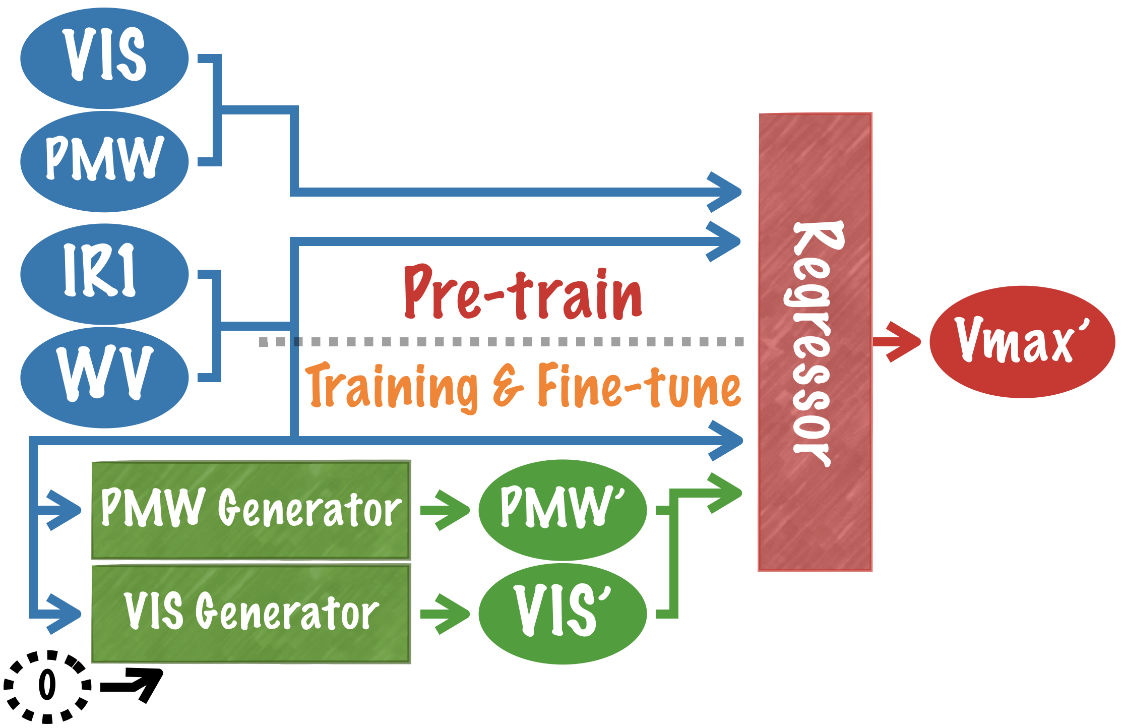
This work proposes a novel deep learning model combining CNN and GAN (generative adversarial network) to deal with the temporally heterogeneous datasets. Our goal is to eliminate the dependency on PMW channel and perform the prediction with only IR1 and WV channels, so that 24/7 intensity estimations could be provided. To keep the performance comparable to the state-of-the-art model, we also make use of the most of the information provided by good quality VIS images. We proposed a novel 5-stage training strategy, with which two separated generators are trained for producing simulated VIS and PMW images. Afterward, generated VIS and PMW images can be used along with IR1 images to conduct the estimates. Fig. 2 is a schematic of our inference model.

We summarize related work about GAN in Section 2 and provide analysis of various used satellite observations in Section 3. Section 4 discusses the hybrid GAN-CNN architecture and the training strategy. Then Section 5 demonstrates the capability of the proposed model dealing with temporally heterogeneous datasets to provide 24/7 intensity estimates in good quality. Section 6 is a quick recap.
2 Background Knowledge
In this section, we summarize several GAN frameworks that inspire our work. In a typical GAN [6], there are two opposing players: a generator and a discriminator. The generator is responsible for generating fake data and trying to confuse the discriminator. A discriminator acts like an umpire, responsible for distinguishing between real and fake data. The competition between both players prompt the generator to generate fake data that is difficult to distinguish from the real data.
CGAN (conditional GAN) [7] attaches conditions to the input of the generator. These conditions should be related to several side information provided by the image, such as the class of the object in the picture. The generator is restricted only to generate images that meet the conditions. Also, the specified conditions will be disclosed to the discriminator along with the generated data. This formulation allows generators to generate images according to our needs.
AC-GAN (auxiliary classifier GAN) [8] follows the steps of CGAN by setting conditions to the generator. Differently, specified conditions are not exposed to the discriminator. Instead, the discriminator are demanded to reconstruct the side information of the images on its own. Compared to CGAN, AC-GAN further improves the stability of training and the quality of the generated data.
In most of GAN frameworks, the discriminator only outputs a single probability to determine whether the entire image is generated or not. In contrast, PatchGAN [9] modifies its discriminator to cut the whole image into multiple small patches with overlap and discriminates them piece by piece. This technique has been proven to be mathematically equivalent to doing blending with data after cutting into patches. This technique is useful for data with even distribution and no distinct boundary, such as satellite images.
U-Net [10] is a type of generators which has similar structure to an auto-encoder. The input and output of U-Net are both images. It retains the local details from the input image by skip connections, then reconstructs them in the corresponding position. Therefore, it is widely used in situations where the input and output are pictures of the same size.
Proposed in 2017, Pix2Pix [11] uses pictures as the condition of the generator and completes the style conversion task brilliantly. Because the inputs of the generator are images, Pix2Pix reasonably uses U-Net as its generator. Meanwhile, the PatchGAN discriminator is used. L1 distance between the input picture and the output picture are added to the generator loss. This term in the loss function directly guides the generator to produce the desired image and is useful for fighting against mode collapse. However, this framework demands data before and after conversion to be paired.
CycleGAN [12] focuses on training two generators (style A-> style B, style B-> style A) at the same time instead of training an one-way generator. CycleGAN requires the input image (assuming style A) can be converted back as similar as possible after passing through both generators. We can thus ensure that the generator retains the critical information in the original image when converting the style. The concept in CycleGAN is similar to an auto-encoder. On the other hand, CycleGAN also resolves the limitation of Pix2Pix that requires the paired data. However, due to the characteristics of TC images, we apply Pix2Pix in our framework, but not that of the CycleGAN. The detailed reasons are described in Section 3.1.
3 Data Analysis and Preprocessing
We conducted our experiment on the benchmark TCIR dataset, which includes 4 channels: Infrared (IR1), Water Vapor (WV), Visible (VIS), and Passive Microwave (PMW). An example is shown in Fig. 1 (a)-(d). For more details about the TCIR, please refer to the previous work of Chen et al. [3].
3.1 Analysis of the PMW Data
According to domain knowledge, PMW is positively correlated with relu(WV-IR1) [13]. Therefore, the Fig. 1(d) and Fig. 1(e) are somewhat similar to each other. This evidence makes us believe that a properly trained Pix2Pix model can hopefully restore the PMW channel using IR1 and WV information. However, since there is still a certain gap between PMW and relu (WV-IR1), we cannot directly use the latter one to replace the former one.
Besides, we also discovered that the conversion is uni-directional. While we can use IR1 and WV to derive PMW, it is challenging to derive IR1 and WV from PMW. Thus, cycleGAN is not recommend to serve as the PMW generator.
3.2 Analysis of the VIS Data
The VIS channel is the noisiest compared with other three channels. Types of effects includes:
-
1.
VIS images are meaningless at night due to the significant decrease in light intensity.
-
2.
Even under the daylight, about 1/5 of the VIS are noisy or completely black.
-
3.
The intensity of sunlight varies at different hours throughout the day. Cloud is more obvious when the time is closer to noon.
-
4.
Similar to other channels, the signal may be disturbed by noises. Sometimes even half of a VIS image is black. Besides, there could be strip noise occasionally.
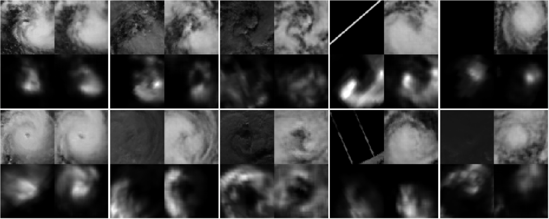
By adopting the VIS generator, we want to (1) generate VIS images with IR1 and WV at all times, even during the night, (2) calibrate sunlight level among all VIS images, and (3) remove block and strip noise. For clearer example, please refer to Fig. 9 in the experiment section.
3.3 VIS Quality Control
A subset of VIS data with good quality is needed to serve as the labeling data and facilitate the training of the VIS generator. This selection was conducted based on the calculation of the mean and standard deviation of the entire image values.
By filtering unusual values of mean, we can exclude all-black and all-white images. On the other hand, a clear VIS image’s standard deviation is likely to fall within a certain interval. After consulting human experts, we subjectively determine the range of reasonable mean and standard deviation in which a high-quality VIS should be (1) and (2) .
Moreover, to further reduce false positives, we limit high-quality visible images to be between 07:00 and 17:00 because it is impossible to have high-quality VIS data during the nighttime, namely our third condition: (3) .
As a result, a total of 12480 TC images (training data) were marked as good quality VIS, accounting for 20.9% of the total 59837 samples in the training data.
4 Proposed Method
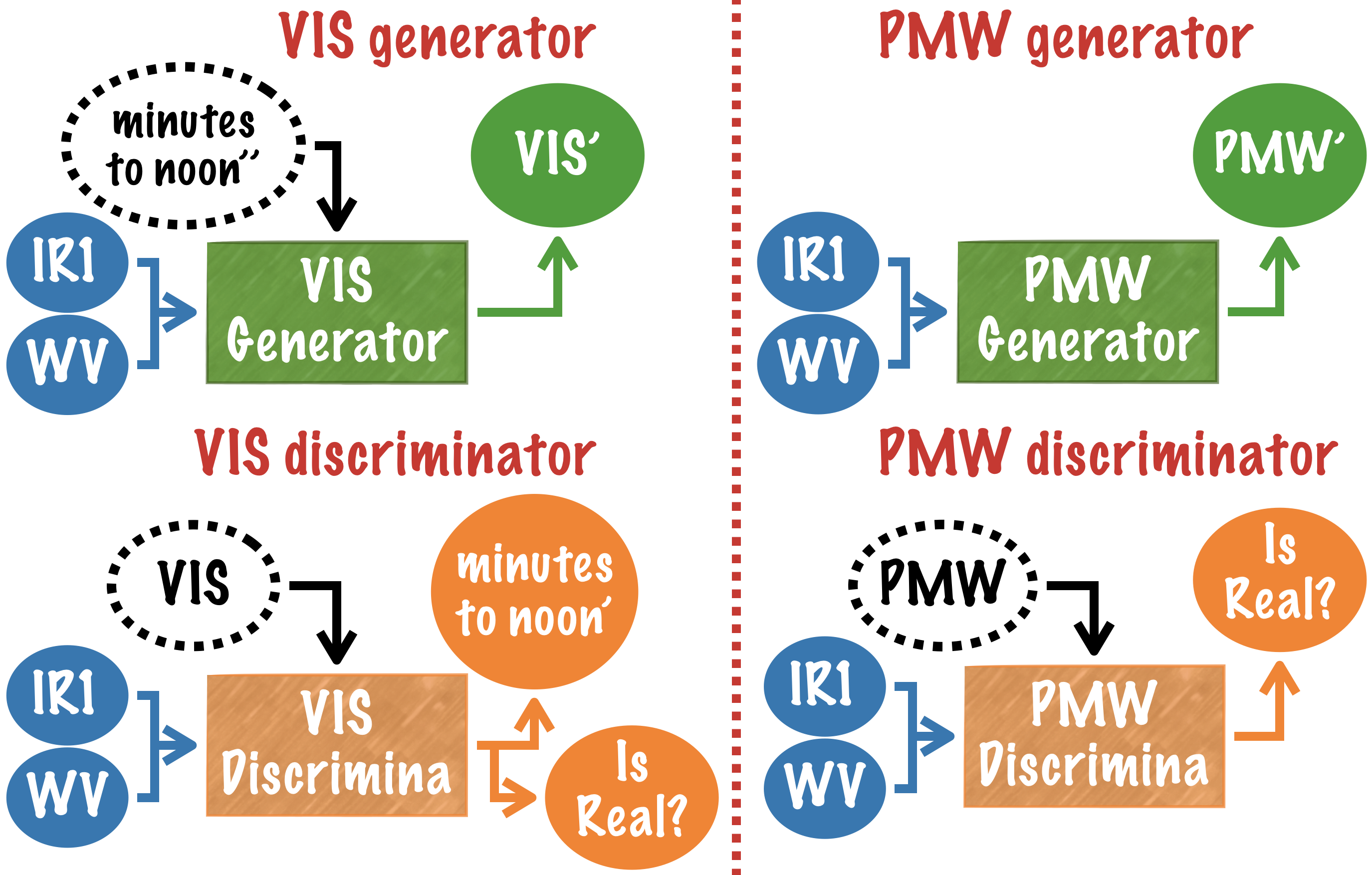
To eliminate the dependence on the usage of PMW and solve problems caused by severe noise in the VIS, we demand GANs that can stably generate VIS and PMW channels only by the two temporally homogeneous channels: IR1 and WV (Fig. 4). In the dataset, every set of TC images have PMW observation, while only 20% have good-quality VIS. To use available information optimally, generators for PMW and VIS are trained separately (Fig. 4).
We use an adjusted U-Net for the generator. Thanks to the skip connections in U-Net, local details in the source image can be preserved. Regarding the discriminator, we use the idea of PatchGAN. Satellite observations are continuous, without concept of objects, foreground, background, and boundaries. Radically speaking, any segmentation of a real TC image can be determined normal because there is no object to be dissected. A PatchGAN divides images into multiple small areas before determining whether it is real, which is suitable for our data and makes training more stable.
4.1 Training Objective
There are three components in this framework: a generator, a discriminator, and a regressor. The loss functions are formulated as:
| (1) | ||||
used in the experiments are listed in Appendix B.
Discriminator loss ()
The goal of the discriminator is to correctly identify the target image as real observation or a fake generated by the generator:
| (2) | ||||
This concept is the same as that in the Pix2Pix.
Generator loss ():
The loss contains the following requirements associated with our loss function. First, the goal of the generator is to confuse the discriminator:
| (3) | ||||
This is equivalent to the loss in the patchGAN.
Second, the generated VIS/PMW must be similar to the input VIS/PMW:
| (4) | ||||
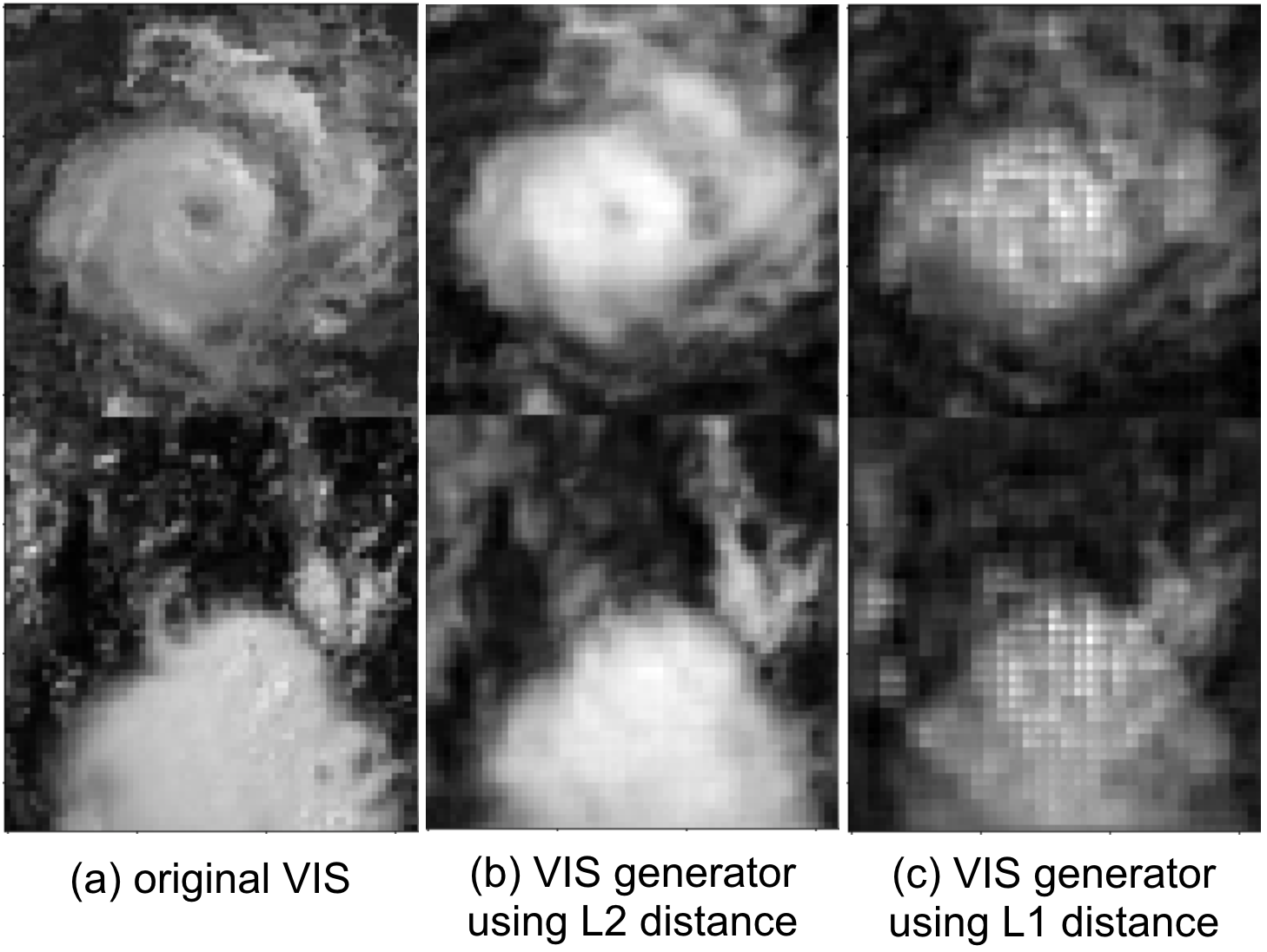
This concept is borrowed from the Pix2Pix. Note, however, that the L2 distance (MSE) is used instead of the L1 distance (MAE) in our model because L2 distance encourages more blurring. Usually, we want to generate images with clear lines and apparent boundaries. However, satellite images have no concept of boundaries, where they are smoother than ordinary pictures, such as dogs, cats, and cars. Therefore, we modify the Pix2Pix architecture based on our need. A comparison of using L1 distance and L2 distance will be shown later in Section 5.2.
Besides, we have added the following two innovative designs to our GANs, specializing the GANs to complete tasks appropriately. The details are described in the following two sub-sections.
Auxiliary time loss ():
As mentioned in Section 3.2,
we expect the VIS generator to adjust all generated VIS images to the sunlight level at noon.
To achieve this goal, we need to first calculate m2n (minutes to noon) for each VIS image:
.
We take m2n as an additional condition and apply the concept of the AC-GAN to our VIS generator and discriminator.
Then loss function therefore has an extra term.
Discriminator:
| (5) |
Generator:
| (6) | ||||
VIS images with good quality were obtained during daytime, specifically from 7:00 to 16:59 (see Section 3.3), so the largest value of minutes to noon is 300. In training, randomly generated floating-point numbers between [0, 300] are provided to the generator as condition.
Regressor loss ():
Since our ultimate goal is to use the generated VIS / PMW channels as the regressor’s inputs, the generator is requested to create useful features that can facilitate estimations.
The generator is first asked to generate PMW and VIS given the condition . The obtained results are provided to the regressor, along with IR1 and WV. Finally we can obtain our intensity estimation using generated VIS / PMW (e.g. lower part of Fig. 4). The precision of the prediction is also added to one of the terms of the generator loss:
| (7) | ||||
The term stands for the maximum wind velocity, the definition of TC intensity.
4.2 Strategy of Three-Stage Training
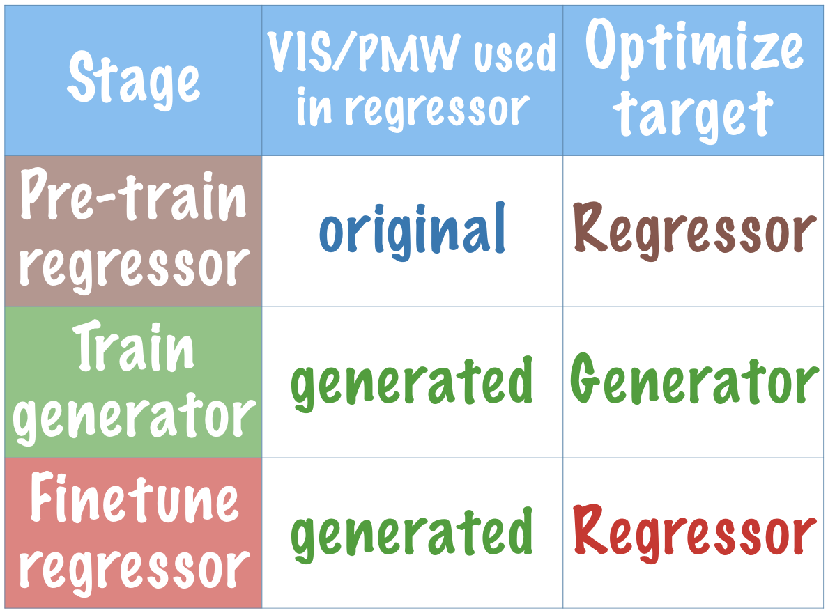
To fairly calculate , we need to pre-train the regressor. Therefore, a novel three-stage training illustrated in Fig. 4 and Fig. 6 is proposed.

-
1.
Pre-train regressor: Pre-train the regressor with original VIS and PMW along with other regressor inputs and thereby let the regressor learns how to extract essential features from real VIS / PMW in advance.
-
2.
Train generator: The generator and discriminator are optimized together. The loss mentioned in Eq. 7 ensures that significant feature regressor is using will be generated.
-
3.
Fine-tune regressor: With well-trained generator, we use the generated VIS / PMW features to fine-tune the regressor.
4.3 Strategy of Five-Stage Training
Good results are achieved through the above procedures of three-stage training. To be even better, VIS generator should be trained with only data with good quality VIS images. Meanwhile, the training process become more stable when 2 generators are only optimized when another one is fixed.
Therefore, based on the three-stage training described above, a more detailed five-stage training process illustrated in Fig. 6 is proposed. In the five-stage training, the first two stages of three-stage training are repeated for two loops:
-
1.
Loop 1: Only data with good quality VIS images are used in this loop. PMW generator is fixed while we focus on optimizing VIS generator. When calculating loss in Eq. 7 we use the original PMW instead of a generated one.
-
2.
Loop 2: All data are used. VIS generator is fixed while we pay attention to PMW generator.
-
3.
After training both generators, regressor get fine-tuned using the generated PMW’ and VIS’.
By applying five-stage training, we obtain the final operational predicting model (Fig. 2).
5 Experiments and Analysis
In the following section, two techniques proposed in the previous work will be explained briefly, including auxiliary features and rotation-blending. Please refer to Chen et al. [4] for more details. Next, we will compare our performance with related works which also focus on estimating TC intensity, including both operational meteorological models and deep learning techniques. Finally, we qualitatively analyze the quality of the proposed model. Detailed model structures and hyper-parameters are disclosed in Appendix A and Appendix B respectively.
In the experiments, we split the dataset into three parts: (1) Training data: TCs during 2000-2014, (2) Validation data: TCs during 2015 and 2016, (3) Testing data: TCs during 2017.
Auxiliary Features:
In addition to the output from convolution layers, additional features are passed into the regressor. The auxiliary features are demonstrated to be helpful in improving the precision of estimation [4]. These features provide clues such as (1) day of year: stand for seasonal information, (2) local time, and the most influential one: (3) One-hot encoded region codes: region codes is in {WPAC, EPAC, CPAC, ATLN, IO, SH}, representing 6 different basins.
Rotation Blending:
Considering the nature of TCs as a rotating weather system, TC data is rotation invariant. That is, rotations with respect to the center usually do not affect the estimation of the TC intensity. [3] demonstrated that the idea of using rotation for augmentation leads to a significant improvement in performance.
During the training phase, each image will be randomly rotated by any degree before feeding into our model. When it comes to inference, images will be rotated by evenly distributed ten angles ranged from 0 to 360 to collect 10 different estimations. Afterward, these intensity estimations are blended to obtain the final estimate.
5.1 Intensity Estimation Performance
The main task of this work is to accurately estimate the TC intensity, which is the output of our model. The unit of TC intensity is knot (kt) defined as its maximum wind speed (Vmax). The value of Vmax is usually ranged in [30, 180], and TCs with a Vmax larger than 96 kt are considered as intense TCs.
Table 1 compares our performance to other works. ADT (Advanced Dvorak Technique) [14] is a common used method to estimate TC intensity, which extract features from IR1 images before applying linear regression. SATCON [1] is the the state-of-the-art model used by meteorologists in operational forecast. It highly rely on observations from low-Earth-orbit satellites.
The performance of our proposed model is comparable to the state-of-the-art model in both deep learning and meteorology, while our model can provide much more timely estimations.
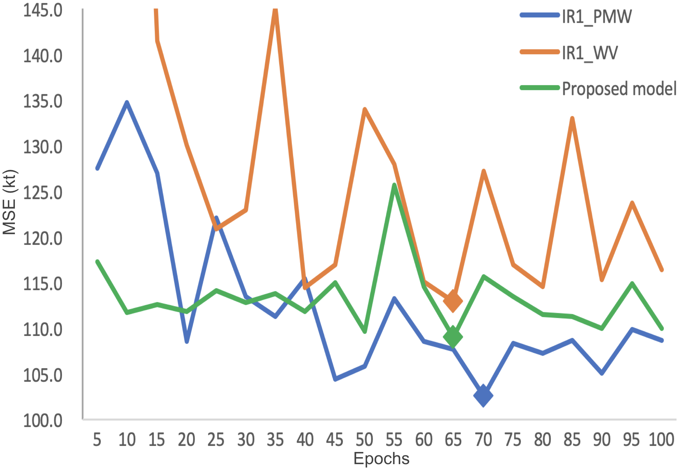
In Fig. 8, we compare the validation MSE score over the first 100 epoch of training. The blue line represents the state-of-the-art model, which provides intensity estimates every 3 hours. The orange and green line shares same inputs, IR1 and WV, which is available every 15 min. The former is the model that directly uses them for estimations while the latter is our proposed model. In contrast, our adequately trained GAN model helps us further improve the performance of intensity estimation, bringing it closer to the state-of-the-art model. Most importantly, our proposed model can provide intensity estimates every 15 min.
| no smoothing | w/ smoothing333Simple smoothing techniques are applied here to obtain a boost in estimation precision [3, 4]. | input | frequency | |||
| valid | test | valid | test | |||
| ADT [14] | 12.65 | IR1 | 30 min 444They are currently providing estimations every 30 mins. But it could be ¡=15 min as well. | |||
| SATCON [1] | 8.59 | IR1, PMW555SATCON depends on low-Earth-orbit satellites observations, which is somehow similar to the PMW. | H | |||
| CNN-TC [4] | 10.38 | – | 8.74 | 8.39 | IR1, PMW | H |
| CNN-TC 666Our reproduction of CNN-TC. We add additional batch normalization layers in our reproduced CNN-TC, which leads to a minor improvement. The modified structure is disclosed in Table 4. | 10.13 | 10.13 | 8.62 | 8.89 | IR1, PMW | H |
| Proposed model | 10.43 | 10.19 | 9.01 | 9.33 | IR1, WV | <= 15 min |
5.2 Effectiveness of the L2 Distance
L2 distance is chosen instead of L1 distance in Eq. 4, which is different from a ordinary Pix2Pix framework. Comparing to commonly seen pictures, satellite observations are continuous and have smoother boundaries. As described in Section 4.1, using L2 distance encourages more blurring. In Fig. 8, we take VIS channels as examples, compare the generated results from models using L1 distance and L2 distance. As shown, the model using L1 distance generates images less smoothly.
5.3 Qualitative Study
Fig. 9 shows the generated images from the proposed model. Compared with the original VIS images, the generated VIS image is slightly blurred, and the eye is not as clear as the original one. Nevertheless, these images can be generated stably anytime, with the removal of most noises, and with adjustment of sunlight intensity.
Interestingly, most of the generated PMW seems to be slightly rotated. This is presumably because observations can only be obtained when the low-Earth-orbit satellites pass across the TCs. Therefore, the time PMW channel being collected could be slightly misaligned with other channels.
6 Conclusion
This paper focuses on improving the utility of deep learning in TC intensity estimation for practical scenarios. A modified Pix2Pix GAN framework is presented to better fit in our unusual TC data that is temporally-heterogeneous, and we combine the GAN with a CNN regressor, eventually becoming our proposed hybrid GAN-CNN model. By properly dealing with temporally-heterogeneous data, our proposed model not only achieves comparable performance with the state-of-the-art model in estimating precision but also provides the estimates much more timely, which leads to better TC warning operations and could eventually save more lives.
Moreover, being capable of estimating TC intensity by only IR1 and WV channels, the new model enables us to reanalyze the intensity of TCs further back to the time only simple IR1 and WV images were available (1980s) instead of starting from 2000s, providing the potential of a breakthrough in the research about climate change and global warming from the aspect of TC activities.
Broader Impact
Timely warnings are critical to a better disaster warning/management system. From Hurricane Katrina to Hurricane Harvey and even to recent COVID-19, we should learn that early awareness of these disaster could result in saving many lives.
Take Hurricane Harvey as example. Back to August 25, 2017, Hurricane Harvey was estimated as a category 2 hurricane during 02:00 to 14:00. After it became a category 3 hurricane at 17:00, all in a sudden, it grew into a category 4 hurricane only 3 hours later at 20:00. Eventually, Hurricane Harvey led to the record-breaking damage in the U.S. To timely monitor this rapid intensification is challenging for the conventional TC intensity estimation techniques, which provides estimates only once per 3 hours. Imagine that if there’s a timely estimation system which can provide intensity estimates every 15 minutes. The insane increasing trend could be detected earlier, precious time could be bought, people could get better prepared, and lives could be saved.
On the downside, a significant pitfall of applying machine learning techniques in disaster management is that models are naturally conservative when facing extreme cases. For example, TC intensity ranges from 20 to 180 kt, while about 70% of the value distributed within 35 kt to 64 kt, which makes it almost unavoidable for machine learning models to under-estimate unprecedented extreme values. Therefore, an auxiliary warning system should exist no matter how precise we humans can be with our machine learning techniques. After all, disaster management is a cost-sensitive scenario in which we should always keep in mind that while false positive is annoying, false negative is deadly.
References
- Velden and Herndon [2014] CS Velden and D Herndon. Update on the satellite consensus (satcon) algorithm for estimating tc intensity. Poster session I. San Diego, 2014.
- Pradhan et al. [2018] Ritesh Pradhan, Ramazan S Aygun, Manil Maskey, Rahul Ramachandran, and Daniel J Cecil. Tropical cyclone intensity estimation using a deep convolutional neural network. IEEE Transactions on Image Processing, 27(2):692–702, 2018.
- Chen et al. [2018] Boyo Chen, Buo-Fu Chen, and Hsuan-Tien Lin. Rotation-blended cnns on a new open dataset for tropical cyclone image-to-intensity regression. In Proceedings of the 24th ACM SIGKDD International Conference on Knowledge Discovery & Data Mining, pages 90–99, 2018.
- Chen et al. [2019] Buo-Fu Chen, Boyo Chen, Hsuan-Tien Lin, and Russell L Elsberry. Estimating tropical cyclone intensity by satellite imagery utilizing convolutional neural networks. Weather and Forecasting, 34(2):447–465, 2019.
- Wimmers et al. [2019] Anthony Wimmers, Christopher Velden, and Joshua H Cossuth. Using deep learning to estimate tropical cyclone intensity from satellite passive microwave imagery. Monthly Weather Review, 147(6):2261–2282, 2019.
- Goodfellow et al. [2014] Ian Goodfellow, Jean Pouget-Abadie, Mehdi Mirza, Bing Xu, David Warde-Farley, Sherjil Ozair, Aaron Courville, and Yoshua Bengio. Generative adversarial nets. In Advances in neural information processing systems, pages 2672–2680, 2014.
- Mirza and Osindero [2014] Mehdi Mirza and Simon Osindero. Conditional generative adversarial nets. arXiv preprint arXiv:1411.1784, 2014.
- Odena et al. [2017] Augustus Odena, Christopher Olah, and Jonathon Shlens. Conditional image synthesis with auxiliary classifier gans. In Proceedings of the 34th International Conference on Machine Learning-Volume 70, pages 2642–2651. JMLR. org, 2017.
- Li and Wand [2016] Chuan Li and Michael Wand. Precomputed real-time texture synthesis with markovian generative adversarial networks. In European conference on computer vision, pages 702–716. Springer, 2016.
- Ronneberger et al. [2015] Olaf Ronneberger, Philipp Fischer, and Thomas Brox. U-net: Convolutional networks for biomedical image segmentation. In International Conference on Medical image computing and computer-assisted intervention, pages 234–241. Springer, 2015.
- Isola et al. [2017] Phillip Isola, Jun-Yan Zhu, Tinghui Zhou, and Alexei A Efros. Image-to-image translation with conditional adversarial networks. In Proceedings of the IEEE conference on computer vision and pattern recognition, pages 1125–1134, 2017.
- Zhu et al. [2017] Jun-Yan Zhu, Taesung Park, Phillip Isola, and Alexei A Efros. Unpaired image-to-image translation using cycle-consistent adversarial networks. In Proceedings of the IEEE international conference on computer vision, pages 2223–2232, 2017.
- Olander and Velden [2009] Timothy L Olander and Christopher S Velden. Tropical cyclone convection and intensity analysis using differenced infrared and water vapor imagery. Weather and forecasting, 24(6):1558–1572, 2009.
- Olander and Velden [2007] Timothy L Olander and Christopher S Velden. The advanced dvorak technique: Continued development of an objective scheme to estimate tropical cyclone intensity using geostationary infrared satellite imagery. Weather and Forecasting, 22(2):287–298, 2007.
Appendix A Model Structure
The model structures for the generator, the discriminator, and the regressor are detailed in Table 2, Table 3, and Table 4 respectively.
| i | Oper | skip | Ker. | Stri. | Dim. | BN | Drop | activ. |
|---|---|---|---|---|---|---|---|---|
| 0 | conv | to 11 | 4x4 | 2x2 | 32 | N | - | leaky |
| 1 | conv | to 10 | 4x4 | 2x2 | 64 | Y | - | leaky |
| 2 | conv | to 9 | 4x4 | 2x2 | 128 | Y | - | leaky |
| 3 | conv | to 8 | 4x4 | 2x2 | 256 | Y | - | leaky |
| 4 | conv | to 7 | 4x4 | 2x2 | 256 | Y | - | leaky |
| 5 | conv | - | 4x4 | 2x2 | 256 | Y | - | leaky |
| 6 | trans_conv | - | 4x4 | 2x2 | 256 | Y | 0.5 | relu |
| 7 | trans_conv | - | 4x4 | 2x2 | 256 | Y | 0.5 | relu |
| 8 | trans_conv | - | 4x4 | 2x2 | 256 | Y | - | relu |
| 9 | trans_conv | - | 4x4 | 2x2 | 128 | Y | - | relu |
| 10 | trans_conv | - | 4x4 | 2x2 | 64 | Y | - | relu |
| 11 | trans_conv | - | 4x4 | 2x2 | 32 | Y | - | relu |
| 12 | conv | - | 4x4 | 1x1 | 1 | N | - | relu |
| Usage | Operation | Ker. | Stri. | Dim. | BN | activ. |
| Shared layers | conv | 4x4 | 2x2 | 32 | N | leaky |
| conv | 4x4 | 2x2 | 64 | Y | leaky | |
| conv | 4x4 | 2x2 | 128 | Y | leaky | |
| Predict m2n | conv | 4x4 | 2x2 | 128 | Y | leaky |
| conv | 4x4 | 2x2 | 256 | Y | leaky | |
| linear | - | - | 128 | Y | relu | |
| linear | - | - | 1 | N | - | |
| Discriminator layers | conv | 4x4 | 1x1 | 256 | Y | relu |
| conv | 4x4 | 1x1 | 1 | N | - |
| Operation | Kernel | Strides | Dim. | BN | activ. |
| BN | - | - | - | Y | - |
| conv | 4x4 | 2x2 | 16 | Y | relu |
| conv | 3x3 | 2x2 | 32 | Y | relu |
| conv | 3x3 | 2x2 | 64 | Y | relu |
| conv | 3x3 | 2x2 | 128 | Y | relu |
| concatenate 10 additional features | |||||
| linear | - | - | 256 | Y | relu |
| linear | - | - | 64 | Y | relu |
| linear | - | - | 1 | N | - |
Appendix B Hyperparameters
The hyperparameters used in the proposed model are shown in Table 5 for reproducibility.
| Stage | (L2) | (regr) | (m2n) | Max epochs |
|---|---|---|---|---|
| Pre-training Regressor | - | - | - | 70 |
| VIS Generator | 1000 | 0.0001 | 0.002 | 500 |
| Pre-training Regressor | - | - | - | 100 |
| PMW Generator | 10 | 0.001 | - | 200 |
| Fine-tune regressor | - | - | - | 300 |