Atom radio-frequency interferometry
Abstract
We realize and model a Rydberg-state atom interferometer for measurement of phase and intensity of radio-frequency (RF) electromagnetic waves. A phase reference is supplied to the atoms via a modulated laser beam, enabling atomic measurement of the RF wave’s phase without an external RF reference wave. The RF and optical fields give rise to closed interferometric loops within the atoms’ internal Hilbert space. In our experiment, we construct interferometric loops in the state space of cesium and employ them to measure phase and intensity of a 5 GHz RF wave in a room-temperature vapor cell. Electromagnetically induced transparency on the to transition serves as an all-optical interferometer probe. The RF phase is measured over a range of , and a sensitivity of 2 mrad is achieved. RF phase and amplitude measurements at sub-millimeter optical spatial resolution are demonstrated.
Interferometry has been foundational to the advancement of science and technology since its inception at the end of the 19th century Michelson (1881). As a means to detect the phase of electromagnetic waves, interferometry is ubiquitous across disciplines from optics Born and Wolf (2013) and metrology Chang et al. (1965), to cosmology Demkowicz-Dobrzański et al. (2015); Spitler et al. (2016), biomedical imaging Park , and optical Gagliardi and Karp (1976) and radio-frequency (RF) communications Flemming (1919). Wave-particle duality De Broglie (1924) and interferometry Ramsey (1950) are fundamentally important for quantum mechanics, atomic and molecular physics, and precision metrology Cronin et al. (2009), from atom interferometry Keith et al. (1991); Kasevich and Chu (1991) and establishing fundamental principles of quantum measurement Brune et al. (1996) to the emergence of quantum technologies MacFarlane et al. (2003) including atomic clocks Essen and Parry (1955); Ludlow et al. (2015) and inertial sensors Wang et al. (2005) for precision timing and navigation.
Interferometric phase sensing is often performed by linear superposition of electromagnetic signal and reference waves of the same or similar frequencies, and using respective homodyne or heterodyne detectors. Multi-spectral phase-sensing of fields that spread across the electromagnetic spectrum, from DC to optical, can be accomplished by wave mixing in macroscopic nonlinear devices, such as nonlinear crystals, mixers, modulators and demodulators. At a fundamental level, phase-coherent, nonlinear wave mixing also occurs in an individual atom, whose Hilbert space provides a grid of states that can be connected via electromagnetic couplings ranging from DC to optical and beyond. In this work, we present an atom interferometer for RF electromagnetic waves: an interferometer in which optical fields and a single RF signal wave connect a pair of atomic states via two paths. The atom RF interferometer is employed for optical measurement of phase and intensity of an RF signal wave via readout of atomic populations Anderson et al. (2018, 2020).
In our atom RF interferometer, RF phase-reference information is transmitted to the atoms via a RF-modulated optical carrier field, preparing the atomic medium in a coherent superposition state of matter that is sensitive to phase and intensity of an incident signal RF wave. The interferometer is implemented with Rydberg states of atoms Bethe and Salpeter (1957); T.F.Gallagher (1994), which are highly susceptible to electric fields ranging from DC to THz. As a readout for the interferometer we use Rydberg electromagnetically induced transparency (EIT) Mohapatra et al. (2007), a method suitable for atom-based sensing in room-temperature vapors. We employ the atom RF interferometer to optically receive and measure the phase and intensity of an RF signal wave.
RF sensing with Rydberg atoms employing fiducial RF reference waves to achieve phase-sensitive and field-enhanced RF sensing has been previously demonstrated Anderson et al. (2018, 2020); Simons et al. (2019); Jing et al. (2020). Our optical interferometric RF phase sensing approach realized in this work differs fundamentally from previous work Sedlacek et al. (2012); Holloway et al. (2014); Anderson et al. (2014, 2016, 2017); Anderson D. A. and Holloway (2017); Meyer et al. (2018); Simons et al. (2019); Meyer et al. (2020); Jing et al. (2020) in which atoms serve as sensors for the intensity of an RF wave. There, information on the relative phase between an RF signal and RF reference wave is extracted from atom-based RF field intensity measurements of the superposition of the external RF waves. In the present paper, we prepare and employ a coherent atomic medium that is sensitive to both phase and intensity of an RF signal wave, without requiring an external RF reference wave.
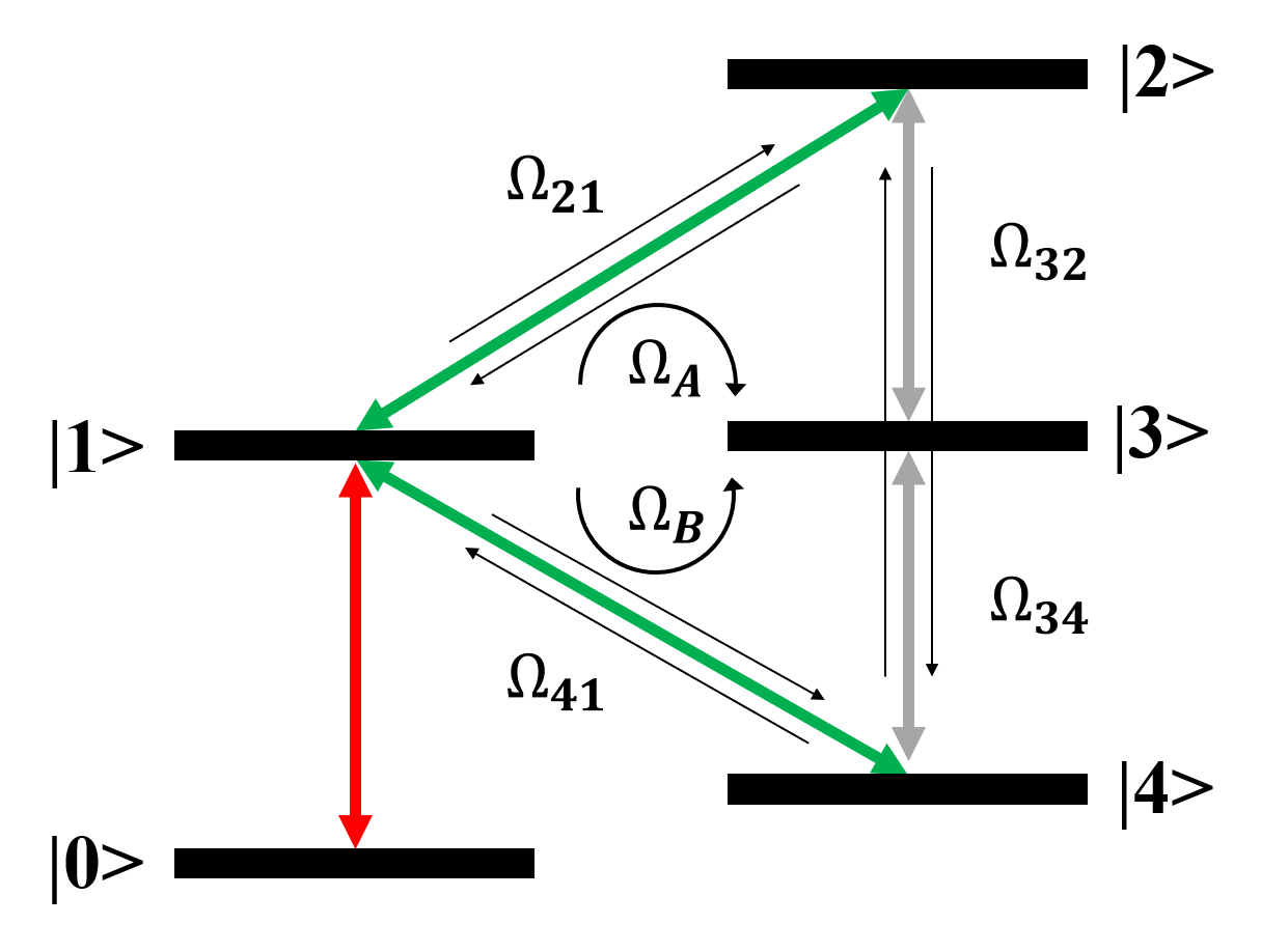
The atomic energy-level and coupling scheme Anderson et al. (2018, 2020) is illustrated in Fig. 1. There, is an optical transition to probe the quantum interference. The and transitions are driven by optical fields (respective frequencies and ), and the and transitions by the signal RF field (frequency ). The frequency difference between the optical fields, , equals . In this way, a closed pair of interfering pathways from to is established, labeled and in Fig. 1, with each path involving one optical and one RF photon. The respective transition amplitudes are
| (1) |
where the are (real-valued) magnitudes of the Rabi frequencies of the transitions from to , and and are detunings that occur in the respective paths, as specified below. The RF signal field carries a phase , and the pair of optical fields carries phases .
The closed interferometric loop exhibits quantum interference between the two pathways associated with and (see Fig. 1). In the case studied, we may set . Phases accumulated along the optical beam paths are compounded in an optical phase difference . The interferometric sum of the excitation amplitudes from to exhibits the atom-interferometric phase dependence,
| (2) |
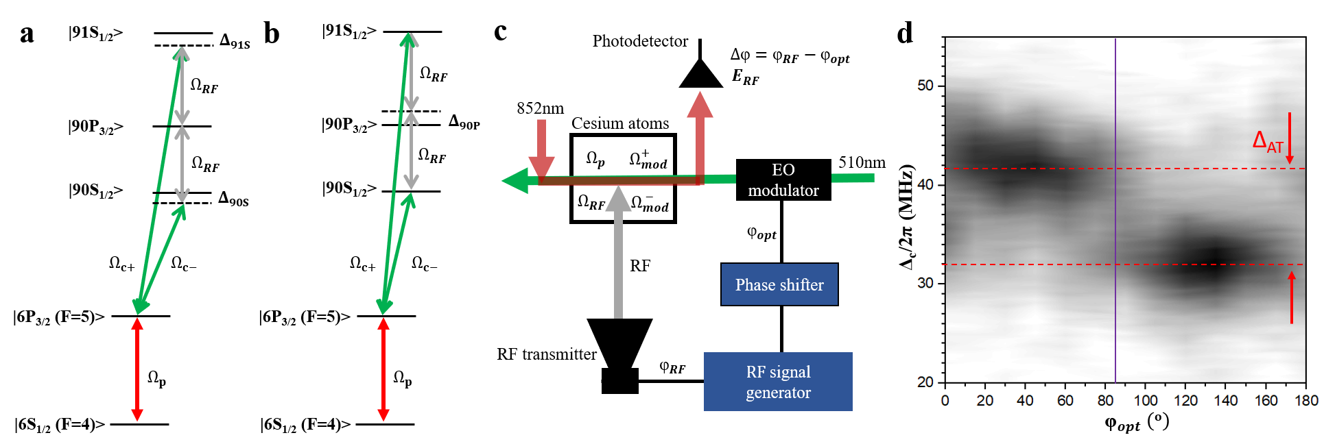
Figures 2a and b show two implementations of the interferometric principle using Rydberg EIT Mohapatra et al. (2007) in a cesium room-temperature vapor cell. The 852-nm EIT probe laser is resonant on the transition (Rabi frequency ), and two 510-nm EIT coupler-laser modes simultaneously drive the and Rydberg transitions (respective Rabi frequencies and ). The Rydberg states and are near-resonantly coupled by the (same) RF field to Rydberg state , with respective Rabi frequencies .
In interferometric loop I, shown in Fig. 2a, the pair of two-photon couplings are both exactly two-photon-resonant, with two-photon Rabi frequencies and as defined in Eq. 1. The intermediate detunings from levels and , labeled and in Fig. 2(a), are generally different but typically have similar magnitude. This system exhibits interference and phase sensitivity as exhibited in Eqs. 1 and 2.
In interferometric loop II, shown in Fig. 2b, the optical couplings and are both essentially on-resonance. The RF field couples levels and in second order via level , with intermediate-state detuning denoted . The detuning from two-photon resonance, with level energies , is typically held near zero, except in Fig. 4b where we explore the effects of a non-zero . The interference in loop-II is seen by first noting that the two-photon RF coupling generates a pair of Autler-Townes (AT)-split states, with AT splitting , that are orthogonal superpositions of and . These states are excited by the two optical coupler-laser modes with the Rabi frequencies . The quantum coherence of the bare atomic constituents and within the AT states, and the phase coherence of the two optical excitation paths with each other and with the RF field impinging onto the atoms, lead to an interferometric dependence of the net excitation amplitude on . The signal in Loop II, observed as a function of the (unmodulated) coupler-laser detuning and , consists of two bands that are separated in by a two-photon AT-splitting (see Fig. 2d). Due to the orthogonality of the AT states, the EIT signals on the AT-pair of Loop-II bands have orthogonal dependencies on the phase .
The EIT probe transmission signal is related to the coupler-light-induced coupling strength , with in the form of Eq. 2. Both Loops I and II allow measurement of an unknown via tuning of , or vice versa. Loop II further yields the RF field intensity by measuring the two-photon AT splitting and the detuning . In the case , the RF intensity, with RF electric field , follows from , with transition electric-dipole matrix elements .
Our experimental setup, illustrated in Fig. 2c, utilizes probe (852 nm) and coupler (509 nm) laser sources that are frequency-stabilized to 100 kHz. The 509 nm coupler laser beam is passed through an electro-optic phase modulator (PM) that is modulated at the RF frequency GHz. The first-order PM sidebands provide a pair of coupler modes separated by in frequency. The EIT coupler modes co-propagate and are counter-aligned with the EIT probe. The optical phase shift is implemented by phase-shifting the RF supplied by the signal generator to the PM. The optical field modes generating the couplings transmit the phase to the atoms, with opposite sign (see Eq. (1)). The signal generator also feeds a horn antenna that transmits the 5 GHz free-space signal wave to the cesium atoms, which are located in the far-field of the antenna. The EIT probe transmission signal is collected on a photoreceiver for read out of the RF interferometer while the frequency offset of the coupler-laser source, , is scanned. In the measurements we map the EIT probe transmission, , in the (, ) plane, revealing the RF phase (Loops I and II) and intensity (Loop II).
In Fig. 2d we determine a fixed, unknown phase using Loop II by measuring for GHz, a case that is near two-photon RF resonance for the Rydberg states chosen in this work. Two EIT bands, corresponding to AT-split states separated by MHz in , extend along the -direction and are modulated in with a period of , as generally expected by taking the square of Eq. 2. The two EIT bands of Loop II are shifted in by relative to each other due to the orthogonality of the two AT-split states. The fringe visibility well exceeds 50%, as seen more clearly in Fig. 3, with limiting factors discussed in our model below. We choose the inflection points of the Loop-II signals to assign a value to the phase of the RF wave to be measured. In Fig. 2d, the measured RF phase is .
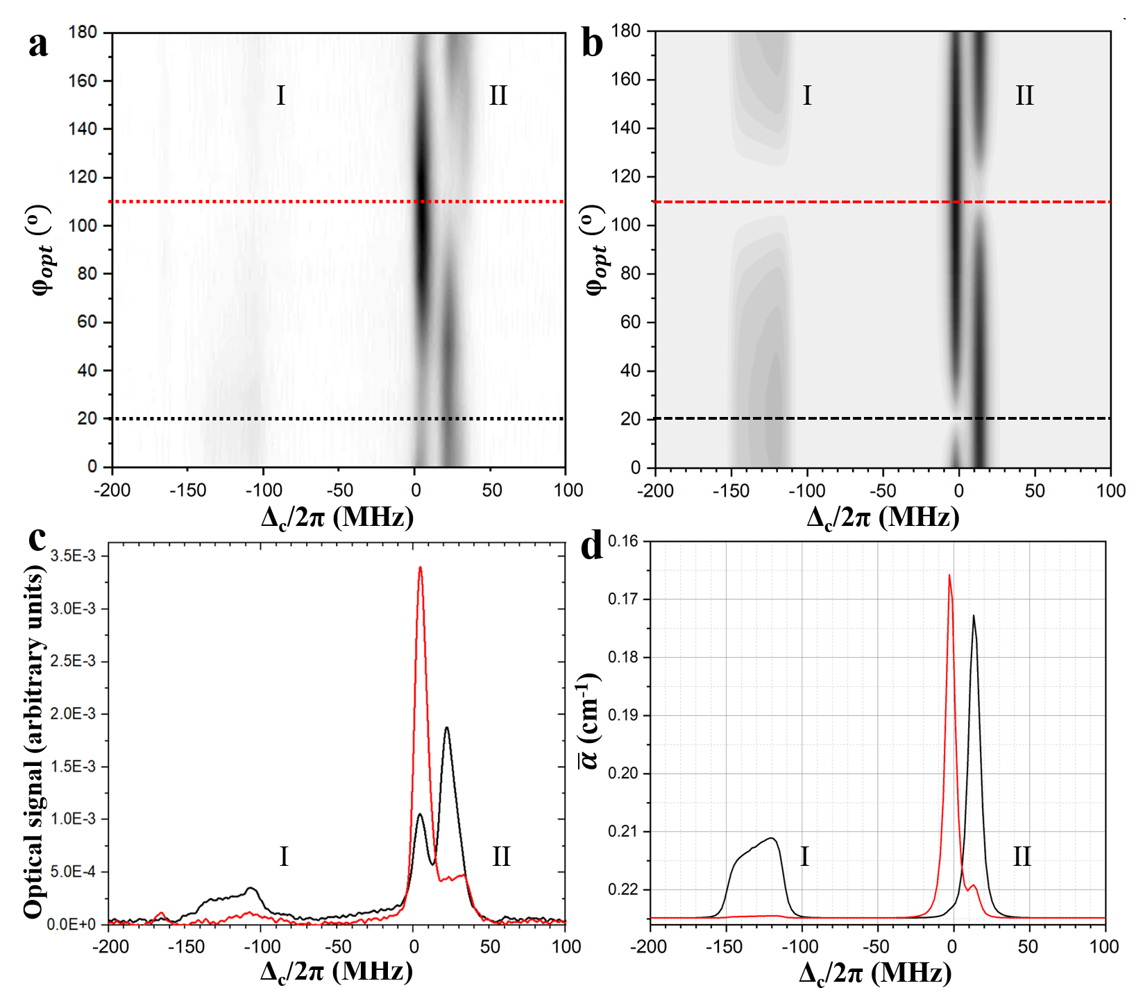
In Fig. 3a we show a similar measurement of both Loops I and II, and in Fig. 3c we plot individual EIT spectra at -values where the loop signals are extremal as a function of . There is a total of three EIT bands at certain values of , with the lowest-frequency band corresponding to Loop I and the two higher-frequency ones to the two AT-split bands of Loop II. Here, MHz, and MHz, taken to be the separation between the center of the Loop-I band and the midpoint between the two Loop-II bands. The Loop-I signal is considerably weaker than that of Loop II due to the presence of a weak DC electric field. The DC field shifts the Loop-I signal from its zero-field value of MHz to MHz, and broadens it over a range of about 30 MHz. Using the experimental values for and and calculated values of and , one finds V/m.
To numerically model the atom RF interferometer measurements in Figs. 3a and c, we obtain the steady-state density operator of the Lindblad equation for the 5-level system of Fig. 2. The absorption coefficient of the cesium vapor for the probe beam is given by
| (3) |
Here, is the density of cesium atoms in the ground state at 293 K, ea0 is the probe electric-dipole matrix element, is the probe-laser wavelength and is its electric-field amplitude, and is the normalized one-dimensional Maxwell velocity distribution at 293 K. The coherence depends on Rabi frequencies, field phases, decay rates, atom-field detunings, and atom velocity . The DC-field-free dressed Rydberg-level detunings at are MHz, , and MHz.We use an optical EIT probe Rabi frequency at the beam center of MHz, and EIT coupler Rabi frequencies at the beam center of MHz. In Fig. 3a and 3c the measured RF Rabi frequencies are MHz and MHz.
We compute weighted averages of from Eq. 3 over the transverse Gaussian profile of the laser beams and over distributions of the DC electric field, , leads to the shift and broadening of the Loop-I signal in Figs. 3a and c. Here, the measured results are reproduced by a flat distribution ranging from =29 mV/cm to 41 mV/cm. Figures 3b and d show the calculated averaged absorption coefficient, , and respective cuts at selected phases , for conditions as in Figs 3a and c. Good agreement is found between experiment and calculation, reproducing the relative phases, AT splittings and linewidths of the signal bands.
The higher-frequency Loop-II band in the experimental data exhibits a correlation between the phase of the EIT signal and the detuning . This is attributed to a spatial correlation between the DC field and the optical-beam propagation phase , with denoting the wavenumber-difference between the two coupler modes and the position along the coupler-beam direction. The reduced visibility in the phase dependencies of the Loop-I and II signals in Fig. 3c relative to those in Fig. 3d is attributed to the propagation phase .
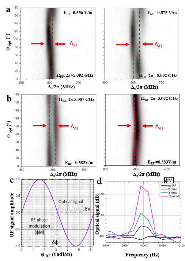
In Fig. 4a we verify the dependence of the Loop-II splitting, , on for the case of two-photon RF resonance, . In that case, one expects , in good qualitative agreement with the measurements shown in Fig. 4a. For non-zero , the Loop-II splitting is given by , the effective, off-resonant two-photon Rabi frequency. This behavior is evident in Fig. 4b, where MHz in the left and in the right panel. The visibility of the phase-dependent modulation of the Loop-I and Loop-II bands is expected to diminish with increasing , which is supported by the measurements in Fig. 4b. The measurements in Figs. 4a and 4b agree well with simulations (not shown).
The static RF phase resolution in the phase measurements in Figs. 2 and 3 is about . In the last component of the present work, we determine the phase resolution achievable using a dynamic interferometric method. For a fixed optical phase near the inflection point , with set at a Loop II-band, we apply a weak phase modulation (PM) of known amplitude to the RF field, with a PM frequency of 10 kHz. Since variations of optical and RF phase have equivalent effects on the optical signal , lock-in detection of at the PM frequency yields a modulation amplitude . In Figs. 4c and d we observe a minimum detectable mrad, limited by the RF hardware.
In summary, we have realized an atom RF interferometer, employed it for all-optical phase measurement of an RF wave with a cesium vapor sensor, and developed a quantum model that reproduces all observed features. A phase resolution of 2 mrad was achieved and RF phase and field measurements were demonstrated at sub-millimeter optical spatial resolution with the atomic sensor. Atom RF interferometry provides a platform to enable new capabilities in optical and RF phase, frequency, and amplitude signal detection, measurement, and imaging, relevant to a broad range of applications in RF and communications technology.
This work was supported by Rydberg Technologies Inc.
References
- Michelson (1881) A. A. Michelson, American Journal of Science 22, 120 (1881).
- Born and Wolf (2013) M. Born and E. Wolf, Principles of optics: electromagnetic theory of propagation, interference and diffraction of light (Elsevier, 2013).
- Chang et al. (1965) R. K. Chang, J. Ducuing, and N. Bloembergen, Phys. Rev. Lett. 15, 6 (1965).
- Demkowicz-Dobrzański et al. (2015) R. Demkowicz-Dobrzański, M. Jarzyna, and J. Kołodyński (Elsevier, 2015) pp. 345 – 435.
- Spitler et al. (2016) L. G. Spitler, P. Scholz, J. W. T. Hessels, S. Bogdanov, A. Brazier, F. Camilo, S. Chatterjee, J. M. Cordes, F. Crawford, J. Deneva, R. D. Ferdman, P. C. C. Freire, V. M. Kaspi, P. Lazarus, R. Lynch, E. C. Madsen, M. A. McLaughlin, C. Patel, S. M. Ransom, A. Seymour, I. H. Stairs, B. W. Stappers, J. van Leeuwen, and W. W. Zhu, Nature 531, 202 (2016).
- (6) D. C. . P. G. Park, Y., Nature Photon 12.
- Gagliardi and Karp (1976) R. M. Gagliardi and S. Karp, Optical communications (1976).
- Flemming (1919) J. A. Flemming, The Principles of Electric Wave Telegraphy and Telephony (Longmans, Green, 1919).
- De Broglie (1924) L. De Broglie, Recherches sur la théorie des quanta, Ph.D. thesis, Migration-université en cours d’affectation (1924).
- Ramsey (1950) N. F. Ramsey, Phys. Rev. 78, 695 (1950).
- Cronin et al. (2009) A. D. Cronin, J. Schmiedmayer, and D. E. Pritchard, Rev. Mod. Phys. 81, 1051 (2009).
- Keith et al. (1991) D. W. Keith, C. R. Ekstrom, Q. A. Turchette, and D. E. Pritchard, Phys. Rev. Lett. 66, 2693 (1991).
- Kasevich and Chu (1991) M. Kasevich and S. Chu, Physical review letters 67, 181 (1991).
- Brune et al. (1996) M. Brune, E. Hagley, J. Dreyer, X. Maître, A. Maali, C. Wunderlich, J. M. Raimond, and S. Haroche, Phys. Rev. Lett. 77, 4887 (1996).
- MacFarlane et al. (2003) A. G. J. MacFarlane, J. P. Dowling, and G. J. Milburn, Philosophical Transactions of the Royal Society of London. Series A: Mathematical, Physical and Engineering Sciences 361, 1655 (2003).
- Essen and Parry (1955) L. Essen and J. V. L. Parry, Nature 176, 280 (1955).
- Ludlow et al. (2015) A. D. Ludlow, M. M. Boyd, J. Ye, E. Peik, and P. O. Schmidt, Rev. Mod. Phys. 87, 637 (2015).
- Wang et al. (2005) Y.-J. Wang, D. Z. Anderson, V. M. Bright, E. A. Cornell, Q. Diot, T. Kishimoto, M. Prentiss, R. A. Saravanan, S. R. Segal, and S. Wu, Phys. Rev. Lett. 94, 090405 (2005).
- Anderson et al. (2018) D. A. Anderson, G. Raithel, E. G. Paradis, and R. E. Sapiro, Patent US20190187198A1 (2018).
- Anderson et al. (2020) D. A. Anderson, R. E. Sapiro, and G. Raithel, IEEE Aerospace and Electronic Systems Magazine 35, 48 (2020).
- Bethe and Salpeter (1957) H. Bethe and E. Salpeter, Quantum mechanics of one- and two-electron atoms (Springer, 1957).
- T.F.Gallagher (1994) T.F.Gallagher, Rydberg Atoms (1994).
- Mohapatra et al. (2007) A. K. Mohapatra, T. R. Jackson, and C. S. Adams, Phys. Rev. Lett. 98, 113003 (2007).
- Simons et al. (2019) M. T. Simons, A. H. Haddab, J. A. Gordon, and C. L. Holloway, Applied Physics Letters 114, 114101 (2019), https://doi.org/10.1063/1.5088821 .
- Jing et al. (2020) M. Jing, Y. Hu, J. Ma, H. Zhang, L. Zhang, L. Xiao, and S. Jia, Nature Physics (2020), 10.1038/s41567-020-0918-5.
- Sedlacek et al. (2012) J. A. Sedlacek, A. Schwettmann, H. Kübler, R. Löw, T. Pfau, and J. P. Shaffer, Nat. Phys. 8, 819 (2012).
- Holloway et al. (2014) C. L. Holloway, J. A. Gordon, A. Schwarzkopf, D. A. Anderson, S. A. Miller, N. Thaicharoen, and G. Raithel, Applied Physics Letters 104, 244102 (2014).
- Anderson et al. (2014) D. A. Anderson, A. Schwarzkopf, S. A. Miller, N. Thaicharoen, G. Raithel, J. A. Gordon, and C. L. Holloway, Phys. Rev. A 90, 043419 (2014).
- Anderson et al. (2016) D. A. Anderson, S. A. Miller, G. Raithel, J. A. Gordon, M. L. Butler, and C. L. Holloway, Phys. Rev. Applied 5, 034003 (2016).
- Anderson et al. (2017) D. A. Anderson, G. Raithel, T. Nithiwadee, S. A. Miller, and A. Schwarzkopf, Patent US 9,970,973 B2 (2017).
- Anderson D. A. and Holloway (2017) S. M. Anderson D. A., Raithel G. and C. L. Holloway, arXiv:1712.08717 (2017).
- Meyer et al. (2018) D. H. Meyer, K. C. Cox, F. K. Fatemi, and P. D. Kunz, Applied Physics Letters 112, 211108 (2018), https://doi.org/10.1063/1.5028357 .
- Meyer et al. (2020) D. H. Meyer, Z. A. Castillo, K. C. Cox, and P. D. Kunz, J. Phys. B: At. Mol. Opt. Phys. 53, 034001 (2020).