∎
33email: martin.mueser@mx.uni-saarland.de
Percolation and Reynolds flow in elastic contacts of isotropic and anisotropic, randomly rough surfaces
Abstract
In this work, we numerically study the elastic contact between isotropic and anisotropic, rigid, randomly rough surfaces and linearly elastic counterfaces as well as the subsequent Reynolds flow through the gap between the two contacting solids. We find the percolation threshold to depend on the fluid-flow direction when the Peklenik number indicates anisotropy unless the system size clearly exceeds the roll-off wave length parallel to the easy flow direction. A critical contact area near 0.415 is confirmed. Heuristically corrected effective-medium treatments satisfactorily provide Reynolds fluid-flow conductances, e.g., for isotropic roughness, we identify accurate closed-form expressions, which only depend on the mean gap and the relative contact area.
1 Introduction
Predicting the leakage rate of seals requires the distribution of the interfacial separation between a surface and the seal to be known. It can only be obtained reliably with accurate contact-mechanics models for the surface-seal system accounting for the microscopic roughness of solids. The quantitative description of such systems can be said to have had three births. James Greenwood and J. B. Williamson (GW) Greenwood1966 formulated the problem in 1966 and suggested a solution to it in terms of non-interacting single-asperity contacts. Bo Persson Persson2001JCP redefined the problem in 2001 by shifting the description and the solution of the contact problem from the real space to Fourier space, which ultimately lead to quite different results than those obtained by GW. Meanwhile, Mark Robbins, who is honored in this issue of Tribology Letters, lead the first efforts to rigorously model numerically the multi-scale nature of roughness Hyun2004PRE ; Pei2005JMPS and kept spearheading contact-mechanics simulations. This gives us the chance to quickly sketch some of Mark’s pioneering contributions to contact mechanics.
Mark understood much better than most of us that modeling is a two-step process: “Reality” is mapped onto mathematical equations in a first step, which then need to be solved in a second step, typically by invoking additional approximations to those while formulating the model. He was one of the few who was strong in both and who would recognize that scrutinizing what approximations can be made in each of the two steps is best made separately. For example, in his second work in the field of contact mechanics Pei2005JMPS he analyzed (i) to what extent plastic deformation matters under what circumstances. He identified rules for (ii) the range of validity of continuum theories for small-scale contacts Luan2005N and worked out (iii) criteria for when randomly rough surfaces are (locally) sticky Pastewka2014PNAS . In other work Campana2008JPCM , he found that (iv) stress and contact auto-correlation functions decay proportionally to , as predicted by Persson Persson2008JPCMb , and not with , as in bearing-area models like GW. Mark also (v) corroborated that Persson theory finds the correct load-displace-ment relation for randomly rough surfaces Persson2007PRL . While it had already been established for moderate load when true contact is spread across the interface Almqvist2011JMPS ; Dapp2012PRL , Mark contributed to noticing that it also applies – after some refinements – when contact is localized near a single asperity Pastewka2013PRE . The just-summarized insights that Mark contributed to the contact mechanics of nominally flat surfaces is but a small fraction of his overall contribution to tribology.
The type of simulations that Mark conducted in his pioneering papers on nominally flat contacts has seen many subsequent works attempting to pick up the crumbs that he left over, such as the subject of this study: contact-area percolation Putignano2013TI ; Yang2019PIME in randomly-rough, mechanical interfaces and the subsequent Reynolds flow through it Dapp2012PRL ; Dapp2016SR ; PrezRfols2017PIME ; PrezRfols2018PRSA ; Vldescu2018JFE ; PrezRfols2018L . This topic is merely one example for the use of full contact-mechanics simulations as starting points.
The description of Reynolds flow in contacts between elastic, isotropic, randomly rough surfaces appears to be well established, at least as long as the surface topographies obey the random-phase approximation Dapp2012PRL ; Persson2004JCP ; Persson2008JPCMa ; Lorenz2009EPL ; Lorenz2010EPJE but also for plastically deformed surfaces violating it PrezRfols2018L ; Persson2016TL . At small pressures, the fluid conductance disappears extremely quickly with decreasing pressure until the dependence becomes roughly exponential at moderate loads—as has been known experimentally for a long time Armand1964V —before it disappears quickly on approach to the percolation threshold Dapp2016SR ; PrezRfols2018L . The exponential regime occurs for relative contact areas between a few percent up to close to the relative contact area at the percolation threshold, , which is believed to be Dapp2012PRL ; Dapp2016SR ; PrezRfols2018L . While other values have also been proposed for , it seems as if the estimate gets approached more closely as more care is taken to simulate meaningful system sizes Yang2019PIME . Just below , the conductance disappears with a power law in Dapp2016SR ; PrezRfols2018L , thereby reflecting the way how individual critical constriction close PrezRfols2018L ; Persson2008JPCMa ; Dapp2015EPL .
In contrast to many other percolation problems, for which “susceptibilities” are dominated on large scales near the percolation threshold Stauffer1994book , prefactors to leakage rates near are determined on the small scale as they depend on how flow is impeded locally by a few last critical constrictions Persson2008JPCMa ; Dapp2016SR ; Persson2020EPJE . Results obtained experimentally or in large-scale simulations are reproduced quite accurately in terms of effective-medium approaches Dapp2012PRL ; Lorenz2010EPJE ; Persson2012EPJE going back to Bruggeman Bruggeman1935AP . Good-quality predictions can also be made with the concept of critical constrictions Persson2008JPCMa ; Persson2020EPJE , unless relative contact areas are very small.
In recent works, Persson extended his contact mechanics theory as well as his subsequent Bruggeman and critical-constriction approaches to anisotropic roughness Persson2012EPJE ; Persson2020EPJE . He pursues various approximations to calculate the conductance tensor for anisotropic media, in particular he assumes that (a) the percolation threshold does not depend on the direction in anisotropic surfaces and (b) quantitative measures for the height anisotropy and the conductance anisotropy are similar.
The assumption of an isotropic percolation threshold could be seen as potentially problematic for the following reason: the height profile for a Peklenik number results from assuming isotropic random roughness on a rectangular domain, which is stretched by a factor of parallel to the -axis and compressed by the same factor parallel to the -axis. In the original domain, both contact patches and fluid channels percolate more easily parallel to the shorter edge of the rectangle than to the longer one. After the stretching/compressing transformation, contact patches and fluid channels tend to be stripes for anisotropic domains and percolation should be eased in the direction of stripes. Thus, even if the flow channel topography could be obtained by the same stretching/compression operation that can be used to generate an anisotropic height profile, probabilities to have open or closed channels right at the percolation threshold would be directionally dependent. Superficial contemplation of flow-channel geometries in small systems easily reinforces the impression that the critical contact area must be greater in the easy direction than in the compressed direction, see, e.g., Fig. 1. However, the two-dimensional anisotropic bond percolation model Redner1979JPA ; Masihi2006PRE exhibits a crossover between one and two-dimensional critical behavior at large system sizes. It yet remains to be seen if elastic contacts obey similar principles. Additional complications may arise due to the possibility that the anisotropy of the contact area and thus of the gaps could be larger than that of the original heights, as is the case for elliptical Hertzian indenters Greenwood1997TI . Quantifying the just-described effects does not appear to be a trivial task, which is why we resort to large-scale simulations in this work.
The remainder of this paper is organized as follows: Sect. 2 presents the pursued models, methods, and some theoretical concepts including some addenda to the Bruggeman treatment for isotropic and unisotropic leakage. Sect. 3 contains the results and their discussion, while final conclusions are drawn in Sect. 4.
2 Model, Methods, Theory
Model, methods, and theory are mostly similar to those used in Refs. Dapp2012PRL ; Dapp2016SR ; Dapp2015EPL . The main difference in the model is that we now also consider anisotropic surfaces and that the used contact-mechanics code was optimized in the meantime. In this section, we focus on these up-dates as well as on aspects that might have remained unclear in previous works along with some additions or corrections to existing Bruggeman approaches to leakage.
2.1 Model
We consider an originally flat, linearly elastic body with contact modulus in contact with a rigid randomly rough indenter on a periodically repeated domain. The height spectrum of the latter obeys the random-phase approximation, i.e., , where is the Fourier transform of the height profile, a linear independent random number drawn on , a wave vector and its effective magnitude
| (1) |
Here, denotes the so-called Peklenik number Peklenik1967PIMEConf ; Li2004TL , whose squared logarithm is a measure for anisotropy. If , “stretching” occurs parallel to the -axis, while it is parallel to the -axis if . Grooves show up parallel to the stretching direction remotely similar to a situation in which a surface was polished or scratched in that direction.
As default for the height spectrum, a continuous transition between the so-called roll-off regime at small wave vectors and the self-affine scaling at large wave vectors is used Majumdar1990 ; Palasantzas1993PRB ; Persson2014TL ; Jacobs2017STMP , specifically
| (2) |
where is called the Hurst exponent, while is the Heaviside step function, which is unity for positive arguments and zero else. and are over short wavelength cutoff and rolloff wavelength, which are denoted by and , respectively. As default values for the height spectrum, we use and The discretization is always made small enough to ensure the continuum limit to be closely approached. We chose such relatively small system sizes, as large anisotropy place large demands on the computational resources. More importantly, we ensured that conclusions do not change when the dimensionless numbers are decreased.
The linearly elastic body and the rigid substrate interact through a non-overlap constraint. They are squeezed against each other with a constant pressure . Once the contact is formed, the interfacial separation is stored and used for further analysis of the Reynolds flow, i.e., we neglect the mechanical pressure exerted by the fluid flow on the contact mechanics. This is certainly a reasonable approximation for leakage problems, all the more the neglected coupling provides only a minor perturbation to the flow factor associated with an individual constriction, while leaving exponents unchanged that define the power laws with which flow approaches zero with increasing load Dapp2015EPL .
The gap topography described by the field defines the local fluid conductivity through the equation
| (3) |
where denotes the viscosity of the fluid and is the local interfacial separation, or brief, gap. The such obtained conductivity is then used in Reynolds thin-film equation
| (4) |
being the areal current density and the in-plane fluid-pressure gradient. Conductances are evaluated parallel to the two principal axes of the simulation cell. Periodic boundary conditions are assumed in the direction normal to the fluid pressure gradient to reduce finite-size effects.
Please note that the term roll-off wavelength and the value of both refer by default to that of the original, isotropic surface. When adding the clause in the easy direction, we mean . In addition, the stand-alone term pressure refers to the mechanical pressure squezing the elastomer against the rigid substrate. The fluid pressure has the added clause fluid.
2.2 Methods
The elastic contact problem is solved using Green’s function molecular dynamics (GFMD) Campana2006PRB , which is used in combination with the fast-inertial relaxation algorithm (FIRE) Bitzek2006PRL as described elsewhere Zhou2019PRB .
The cluster analysis is based on the Hoshen-Kopelman (HK) algorithm Hoshen1976PRB , which identifies connected contact or non-contact (fluid) clusters. If two nearest neighbors are either both contact or both non-contact they belong to the same cluster. A cluster is called percolating when it extends from one side of the domain to the other. Finally, the Reynolds equations is solved as described in Ref. Dapp2015EPL using the hypre package Falgout2006 and the conjugate-gradient minimizer supplied with it.
All simulations and analysis were conducted with house-written codes.
2.3 Theory
Different aspects of the contact-mechanics theory by Persson relevant to this study have been described numerous times. Particularly relevant to this study are those works describing how to use the Bruggeman effec-tive-medium approximation Lorenz2010EPJE ; Dapp2012PRL ; Persson2012EPJE ; Bruggeman1935AP using the gap-distribution function .
2.3.1 Bruggeman effective-medium approach
The self-consistent equation needed to be solved in order to estimate the conductance in the Bruggeman formalism reads Persson2012EPJE
| (5) |
where is the conductivity at a given point, is its distribution function, and the (effective) spatial dimension. In the original treatment, is taken as the true spatial dimension, i.e., for an interfacial leakage problem.
The conductance approaches zero when the probability for zero conductivity exceeds . This result inspired Dapp et al. Dapp2012PRL to use heuristically an effective spatial dimension
| (6) |
in the Bruggeman effective-medium approach. In a similar spirit, Persson generalized Eq. (5) to
| (7) |
with
| (8) |
for anisotropic media characterized by . One flaw of Eq. (7) is that it predicts different flows in and direction when the entire contact is assigned the same microscopic conductivity when is used, i.e., if . To fix this, we modified Eq. (7) to
| (9) |
As another consequence of our correction, the ratio now approaches for as is the case in the anisotropic Bruggeman solution using , as well as in the critical-constriction approach.
2.3.2 Addendum to the Bruggeman approach on isotropic media
Persson theory allows the relative contact area and the average gap to be estimated as a function of pressure Persson2007PRL ; Almqvist2011JMPS ; Dapp2012PRL ; Yang2008JPCM , even for generalized elastomers such as thin sheets or elastomers with gradient elasticity Muser2020TL much more easily than the gap distribution function. The question arises if simple order-of-magnitude estimates for the fluid conductance can be obtained using only and the relative contact area. To achieve that, we rewrite Eq. (5) as
| (10) |
where the characteristic non-contact conductivity is defined through
| (11) |
whose calculation necessitates knowledge of . Here, indicates an average over non contact.
Keeping formally (although it still needs to be determined later), Eq. (10) can be solved for to yield
| (12) |
which, after insertion into Eq. (11), leads to the following self-consistent equation for :
| (13) |
with . Since cannot diverge but only be finite or approach zero as tends to , is predicted to disappear linearly or even faster with decreasing distance from the percolation threshold.
The power law, with which disappears as is approached, depends on the shape of the gap distribution function , from which the conductivity distribution function follows via . This is best discussed by approximating the gap distribution function at small (which is decisive for whether or not the relevant integrals converge) with . For , is easily shown to remain positive no matter how closely the lower integration bound approaches zero, while a positive exponent leads to an algebraic disappearance in for . For , the disappearance is only logarithmic.
In the case of short-range adhesion, adhesive necks form with an infinite slope of the gap at the contact line close, which effectively induces . A dependence follows, as observed in simulations using short-range adhesion Dapp2016SR ; Dapp2015EPL . A faster than linear power-law disappearance of in is predicted for repulsive contacts for which . This is again consistent with previous simulations Dapp2015EPL ; Dapp2016SR finding with . Finally bearing-area models implicitly assume so that logarithmic corrections would apply to the proportionality. Although the critical behavior was not analyzed in detail, this is again consistent with the observation that the conductance disappears substantially more slowly with increasing contact area for overlap models than for true elastic contacts Dapp2012PRL .
To account heuristically for any observed dependence, we propose to use
| (14) |
where is a correction function, or, depending on context or viewpoint also a “fudge-factor” function, into which correct criticality can be encoded by choosing it as
| (15) |
where should be of order unity. A summary of the expected conductance reads,
| (16) |
in which the prefactor (and in the case of the bearing-model an additive constant) was selected such that assumes a value of a at zero contact area, while the finite-contact-area correction factor makes the conductance disappear with the correct power law as is approach, as deduced from the scaling of in the limit of .
2.3.3 Critical-constriction approach
The critical-constriction approach to the leakage rate of seals was introduced in Refs. Persson2004JCP ; Persson2008JPCMa and extended to anisotropic roughness recently Persson2020EPJE . The theory is based on the idea that fluid flow at contact areas close to the percolation threshold is impeded by a random distribution of narrow constrictions through which the fluid has to be squeezed and that the dominant part of the fluid pressure falls off at these constrictions. In an interface, the number of such constrictions per unit length in and direction scales as and , respectively. In a percolating channel, fluid flows through some narrow constrictions with random directions. Even in the case of anisotropy, the flow in a macroscopically large system has to go occasionally through a constriction in which the flow direction is perpendicular to the easy flow direction.
For and , there are as many critical constriction in the -direction as in the -direction so that an equivalent circuit diagram of the fluid flow consists of a single critical constriction. This allows one to focus on just a single characteristic constriction and the question how it impedes fluid flow as a function of the geometry of this constriction. We refer to the original literature Persson2004JCP ; Persson2008JPCMa for how to estimate its geometry theoretically and thus its resistance to fluid flow.
3 Results
3.1 Preliminary considerations
To set the stage for further discussion, flow channels for an isotropic but rectangular domain of a unit area are compared to those in a square, anisotropic domain, which is obtained from the former by scaling the -direction with and the -direction with . This comparison is made in Fig. 1, which shows the height profile in panel (a) and contrasts the points of finite conductivity at a relative contact area of for the isotropic and anisotropic surface in panels (b) and (c), respectively. The original, rectangular domain is characterized by , , , , and . Both surfaces are at % relative contact area.
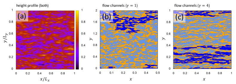
The expectation that stretching cannot change the percolation threshold, because the flow channel topology remains the same before and after the stretching/ compression operation Persson2020EPJE is not fully supported in the simulations. Although changes in the height profiles (not shown) are relatively minor, the fluid-channel topographies—and even topologies—shown in panels (b) and (c) of Fig. 1 differ between the original and the stretched surfaces. New percolating flow channels and percolating contact patches can open up after the stretching operation, while others disappear or merge. Both flow channels and contact patches of the elastic contact are even more stretched than the height profile. A related elongation of contact patches also occurs in isolated Hertzian contacts with elliptical indenters Greenwood1997TI .
A superficial contemplation of just this one random realization depicted in Fig. 1 can easily convey the impression that an elastic contact characterized by the dimensionless numbers , , and should percolate parallel to the stretching direction but not parallel to the orthogonal direction, even if the ratio of linear dimension and were larger than in the just-investigated example. However, a numerical analysis and finite-size scaling () is required to test the validity of this expectation.
3.2 Percolation threshold
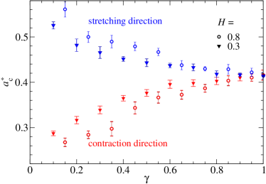
In this section, we investigate how different dimensionless numbers characterizing the surface topograhy affect the percolation threshold. Towards this end, ten independent random realizations were typically set up to determine the order of magnitude of the stochastic error bars. Fig. 2(a) reveals that the percolation thresholds along the two principal directions do not depend strongly on the ratio , i.e., increasing it by a factor of 4 from 16 to 64 only has a relatively minor effect, which is clearly less than the stochastic error bar for close to unity. which remains within the stochastic error bars.
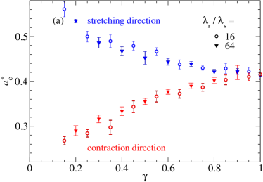
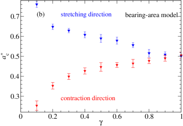
An interesting feature revealed in Fig. 2(a) is that the difference between the critical contact areas in the easy and the compression direction increases with increasing anisotropy, although the system size kept being increased proportionally to . To test if this trend can be explained by the observation that the gap does not transform in the same self-affine fashion as the height, we also computed along the two principal directions for a bearing model, in which stretching and compressing is an affine transformation. In bearing-area models, contact is implicitly assumed to occur above a given substrate height and non-contact, i.e., open fluid flow channels, below it. Fig. 2(b) reveals that the growth of asymmetry of the critical contact areas with increasing is similar for the bearing model as in the full elastic calculation. At moderate , the main difference between the two is a shift of in the elastic model to in the bearing model.
Although the system size was increased proportionally to the square root of the (inverse) Peklenik number for the analysis presented in Fig. 2, the possibility remains that a further increase in system size suppresses the observed anisotropy in . This expectation is confirmed in Fig. 3, which shows that a unique percolation threshold of is approached for the investigated system with size corrections that are close-to-linear power laws in .
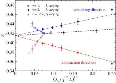
The size scaling revealed in Fig. 3 is consistent with results for regular random-bond-percolation models. Its correlation length increases as and an exponent of for an interfacial dimension of Stauffer1979PR . Thus, the channels percolate along the easy direction at a finite size when so that the size-dependent corrections of the relative contact area, satisfy
| (17) |
which yields a size correction to of order . Renormalization group theory arguments would then indicate that the exponents describing size directions for the easy-flow direction and the contraction direction must be identical, however, the corrections must have opposite signs and may differ in magnitude.
It is currently not clear to us why the exponent are identical or at least close for the considered elastic contact problem and the regular bond-percolation model, as there is no reason why percolation in elastic contacts should be in the same universality class as random-bond percolation. In fact, the so-called Fisher exponent for the cluster-size distribution differs between them. It turns out for regular bond percolation Stauffer1979PR but for the contact-patch-size distribution in repulsive, elastic contacts Muser2018L .
3.3 Reynolds flow
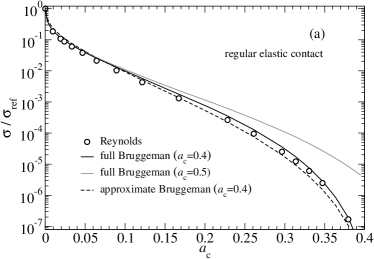
We start this section with the analysis of the Reynolds flow in isotropic contacts. It has already been demonstrated earlier Dapp2012PRL ; Dapp2016SR that the Bruggeman effective-medium theory allows the “exact” Reynolds fluid conductance to be predicted quite accurately. In this paper, we test the validity of the closed-form analytical expressions proposed for the isotropic conductance, which are summarized in Eq. (16). In order to automatically yield good statistics, the system size was increased from its default size to , while the ratio was kept as before. Fig. 5 reveals that the analytical approximations to the full Bruggeman theory are quite reasonable. Relative deviations from either the numerically accurate solution of the full Reynolds problem or the exact solution generally remain around 20% in the shown domains, except for the adhesive case, where the full and the approximate Bruggeman approach differed by a factor of two close to the percolation threshold.
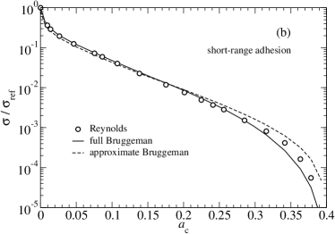
The comparison between exact Reynolds and full as well as approximate Bruggeman theory also adresses adhesive interface, which is shown in Fig. 5(b). The strength and the range of adhesion were chosen such that it lead to a non-negligible enhancement of local contact area, i.e., at zero load we observed 1% “spontaneous” relative contact area and to induce a relative contact area of 10% (40%) only 1/8 (1/4) of the force was required as for its non-adhesive analogue. In more detail, the local Tabor parameter, as defined in Ref. Muser2016TI , was set to , while the reduced surface energy, using the so-called Pastewka-Robbins parameter, see Eq. (16) in Ref. Muser2016TI , was . Thus, no (local) stickiness can be expected despite the relatively large contact-area enhancement. Also the ratio of surface energy and the elastic energy per unit surface needed to bring the two surfaces into the contact, , was well below unity, namely further supporting the absence of hysteresis. In fact, there is a roughly constant, mere 10% adhesion-induced reduction of the mean gap as a function of pressure in the studied range of forces but no signs of significant hysteresis. Thus, we would call the adhesion “intermediate”, i.e., strong enough to substantially increase the relative contact area but not so large as to lead to substantial hysteresis.
While the proposed dependence of conductance on mean gap and relative contact area summarized in Eq. (16) worked well for all case studies performed for this study, it should be clear that estimates can be rough close to the percolation threshold. This is because any short- but finite-range adhesion crosses over to as the true percolation is approached, see also Fig. 5 in Ref. Dapp2016SR . Likewise, if we had used very weak but zero-ranged adhesion, the trend might reverse, i.e., the conductance could be be proportional to close but not too close to the percolation threshold but obey in the immediate vicinity of the percolation threshold. Thus, to be on the safe side, we recommend doing a full Bruggeman analysis (if possible), while its closed-form approximation can only provide crude estimates for the conductance if the relative importance of adhesion is difficult to ascertain.
The last analysis of this work concerns the fluid conductance for anisotropic surfaces for a system described by a Peklenik number of . Fig. 6 reveals that the generalization of the Bruggeman treatment for anisotropic elastic contacts conveys correct trends but shows a somewhat weaker agreement with the full Reynolds calculations than for isotropic surfaces.
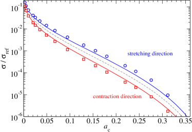
A quantitative analysis of the conductances reveals a ratio of , which is twice the theoretically expected number using the height Peklenik number () to quantify the conductance anisotropy. A certain discrepancy from the theoretical expectation remains when using instead the conductance Peklenik number of , which we deduced from the direction-dependent conductivity auto-correlation function (not shown). Thus using “true” conductivity Peklenik numbers leads to a predicted ratio of , which reduces the error between exact Reynolds calculations () and effective Bruggeman () theory only by a little more than a factor of two.
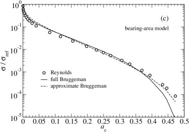
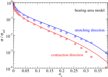
To investigate the origin of the relatively large discrepancy between the exact Reynolds flow and the effec-tive-medium results for elastic contacts, we also considered unisotropic bearing contacts, where conductivity and height anisotropy are identical. The results shown in Fig. 7 reveal a similarly close resemblance of the approximate solutions and the numerically exact results as for isotropic elastic contacts. We are tempted to explain the relatively poor performance of the effective-medium theory near the percolation threshold with the following argument: the anisotropy that elastic deformation induces in addition to the original stretching of the heights is particularly large near the critical constrictions.
4 Summary and Conclusions
In this work, we found that the relative contact area at which fluid channels no longer percolate across a sufficiently large system is and that this value also holds for surfaces with anisotropic random roughness. This confirms Persson’s conjecture that elastic anisotropic contacts have a percolation threshold, which does not depend on the direction. However, requirements on what is called “sufficiently large” are the more stringent the greater the anisotropy. In addition, quantitative measures for anisotropy, such as the Peklenik number, turn out larger for the fluid conductivity than for the height of the randomly rough indenter, at least within linearly elastic contact mechanics. For bearing models, both yield identical Peklenik numbers.
We also proposed a simplification as well as a minor correction to the Bruggeman effective-medium theory, which had been worked out by Persson for the description of leakage in mechanical (elastic) contacts. First, for isotropic contacts, we proposed quite simple, closed-form expressions for the fluid-flow conductance in isotropic contacts, which necessitates only knowledge of the mean gap and the relative contact area as well as the type of contact (repulsive versus adhesive or in the odd case bearing-area contact) but it does not need as input the entire gap distribution function. Second, we corrected the way in which an effective dimension is used in the Bruggeman approach to anisotropic roughness in order to enforce the correct percolation threshold. Both addenda to previous treatments were supported to our satisfaction by full Reynolds simulations.
Finally, Persson’s adaptation of the effective-medium theory to describe direction-dependent conductances for anistropic media works very well for bearing-area contacts, for which (a) the height- and conductance Peklenik numbers are identical and (b) the percolation threshold assumes the canonical value of . However, the generalization to anisotropic, elastic contacts is not quite as satisfactory. It may well be that the way in which the correct percolation threshold is “enforced” for elastic contacts through the use of an effective interfacial dimensions, see Eq. (9), can be further improved. Nonetheless, we find the approximate solution astoundingly good in all cases given the simplicity of the effective-medium theory and the numerical complexity of a full Reynolds calculation.
References
- [1] J. A. Greenwood and J. B. P. Williamson. Contact of nominally flat surfaces. Proceedings of the Royal Society A: Mathematical, Physical and Engineering Sciences, 295(1442):300–319, dec 1966.
- [2] B. N. J. Persson. Theory of rubber friction and contact mechanics. The Journal of Chemical Physics, 115(8):3840, 2001.
- [3] S. Hyun, L. Pei, J.-F. Molinari, and M. O. Robbins. Finite-element analysis of contact between elastic self-affine surfaces. Physical Review E, 70(2):026117, aug 2004.
- [4] L. Pei, S. Hyun, J. Molinari, and M. O. Robbins. Finite element modeling of elasto-plastic contact between rough surfaces. Journal of the Mechanics and Physics of Solids, 53(11):2385–2409, nov 2005.
- [5] Binquan Luan and Mark O. Robbins. The breakdown of continuum models for mechanical contacts. Nature, 435(7044):929–932, June 2005.
- [6] Lars Pastewka and Mark O. Robbins. Contact between rough surfaces and a criterion for macroscopic adhesion. Proceedings of the National Academy of Sciences, 111(9):3298–3303, February 2014.
- [7] Carlos Campañá, Martin H. Müser, and Mark O. Robbins. Elastic contact between self-affine surfaces: comparison of numerical stress and contact correlation functions with analytic predictions. Journal of Physics: Condensed Matter, 20(35):354013, aug 2008.
- [8] B. N. J. Persson. On the elastic energy and stress correlation in the contact between elastic solids with randomly rough surfaces. Journal of Physics: Condensed Matter, 20(31):312001, jun 2008.
- [9] B. N. J. Persson. Relation between interfacial separation and load: A general theory of contact mechanics. Physical Review Letters, 99(12):125502, sep 2007.
- [10] A. Almqvist, C. Campañá, N. Prodanov, and B. N. J. Persson. Interfacial separation between elastic solids with randomly rough surfaces: Comparison between theory and numerical techniques. Journal of the Mechanics and Physics of Solids, 59(11):2355–2369, nov 2011.
- [11] Wolf B. Dapp, Andreas Lücke, Bo N. J. Persson, and Martin H. Müser. Self-affine elastic contacts: Percolation and leakage. Phys. Rev. Lett., 108(24):244301, jun 2012.
- [12] Lars Pastewka, Nikolay Prodanov, Boris Lorenz, Martin H. Müser, Mark O. Robbins, and Bo N. J. Persson. Finite-size scaling in the interfacial stiffness of rough elastic contacts. Physical Review E, 87(6):062809, jun 2013.
- [13] Carmine Putignano, Luciano Afferrante, Giuseppe Carbone, and Giuseppe P. Demelio. A multiscale analysis of elastic contacts and percolation threshold for numerically generated and real rough surfaces. Tribology International, 64:148–154, August 2013.
- [14] Zhimeng Yang, Xiaoyu Ding, Jianhua Liu, and Feikai Zhang. Effect of the finite size of generated rough surfaces on the percolation threshold. Proceedings of the Institution of Mechanical Engineers, Part C: Journal of Mechanical Engineering Science, 233(16):5897–5902, June 2019.
- [15] Wolf B. Dapp and Martin H. Müser. Fluid leakage near the percolation threshold. Scientific Reports, 6(1), February 2016.
- [16] Francesc Pérez-Ràfols, Roland Larsson, Egbert J van Riet, and Andreas Almqvist. On the flow through plastically deformed surfaces under unloading: A spectral approach. Proceedings of the Institution of Mechanical Engineers, Part C: Journal of Mechanical Engineering Science, 232(5):908–918, February 2017.
- [17] F. Pérez-Ràfols, P. Wall, and A. Almqvist. On compressible and piezo-viscous flow in thin porous media. Proceedings of the Royal Society A: Mathematical, Physical and Engineering Sciences, 474(2209):20170601, January 2018.
- [18] Sorin-Cristian Vlădescu, Carmine Putignano, Nigel Marx, Tomas Keppens, Tom Reddyhoff, and Daniele Dini. The percolation of liquid through a compliant seal—an experimental and theoretical study. Journal of Fluids Engineering, 141(3), September 2018.
- [19] Francesc Pérez-Ràfols and Andreas Almqvist. An enhanced stochastic two-scale model for metal-to-metal seals. Lubricants, 6(4):87, October 2018.
- [20] B. N. J. Persson, O. Albohr, C. Creton, and V. Peveri. Contact area between a viscoelastic solid and a hard, randomly rough, substrate. The Journal of Chemical Physics, 120(18):8779–8793, May 2004.
- [21] B N J Persson and C Yang. Theory of the leak-rate of seals. Journal of Physics: Condensed Matter, 20(31):315011, July 2008.
- [22] B. Lorenz and B. N. J. Persson. Leak rate of seals: Comparison of theory with experiment. EPL (Europhysics Letters), 86(4):44006, May 2009.
- [23] B. Lorenz and B. N. J. Persson. Leak rate of seals: Effective-medium theory and comparison with experiment. The European Physical Journal E, 31(2):159–167, February 2010.
- [24] B. N. J. Persson. Leakage of metallic seals: Role of plastic deformations. Tribology Letters, 63(3), August 2016.
- [25] G. Armand, J. Lapujoulade, and J. Paigne. A theoretical and experimental relationship between the leakage of gases through the interface of two metals in contact and their superficial micro-geometry. Vacuum, 14(2):53–57, February 1964.
- [26] Wolf B. Dapp and Martin H. Müser. Contact mechanics of and reynolds flow through saddle points: On the coalescence of contact patches and the leakage rate through near-critical constrictions. EPL (Europhysics Letters), 109(4):44001, February 2015.
- [27] D. Stauffer and A. Aharony. Introduction to Percolation Theory. Taylor and Francis, London, 2nd edition, 1994.
- [28] B. N. J. Persson. Interfacial fluid flow for systems with anisotropic roughness. The European Physical Journal E, 43(5), May 2020.
- [29] B. N. J. Persson, N. Prodanov, B. A. Krick, N. Rodriguez, N. Mulakaluri, W. G. Sawyer, and P. Mangiagalli. Elastic contact mechanics: Percolation of the contact area and fluid squeeze-out. The European Physical Journal E, 35(1), January 2012.
- [30] D. A. G. Bruggeman. Berechnung verschiedener physikalischer konstanten von heterogenen substanzen. i. dielektrizitätskonstanten und leitfähigkeiten der mischkörper aus isotropen substanzen. Annalen der Physik, 416(7):636–664, 1935.
- [31] S Redner and H E Stanley. Anisotropic bond percolation. Journal of Physics A: Mathematical and General, 12(8):1267–1283, August 1979.
- [32] Mohsen Masihi, Peter R. King, and Peyman Nurafza. Effect of anisotropy on finite-size scaling in percolation theory. Physical Review E, 74(4), October 2006.
- [33] J. A. Greenwood. Analysis of elliptical Hertzian contacts. Tribology International, 30(3):235–237, March 1997.
- [34] J. Peklenik. New developments in surface characterization and measurements by means of random process analysis. Proceedings of the Institution of Mechanical Engineers, Conference Proceedings, 182(11):108–126, September 1967.
- [35] Wang-Long Li and Wen-Tung Chien. Parameters for roughness pattern and directionality. Tribology Letters, 17(3):547–551, October 2004.
- [36] A. Majumdar and C. L. Tien. Fractal characterization and simulation of rough surfaces. Wear, 136(2):313–327, mar 1990.
- [37] G. Palasantzas. Roughness spectrum and surface width of self-affine fractal surfaces via the k-correlation model. Physical Review B, 48(19):14472–14478, nov 1993.
- [38] B. N. J. Persson. On the fractal dimension of rough surfaces. Tribology Letters, 54(1):99–106, mar 2014.
- [39] Tevis D B Jacobs, Till Junge, and Lars Pastewka. Quantitative characterization of surface topography using spectral analysis. Surface Topography: Metrology and Properties, 5(1):013001, jan 2017.
- [40] Carlos Campañá and Martin H. Müser. Practical Green’s function approach to the simulation of elastic semi-infinite solids. Phys. Rev. B, 74(7):075420, aug 2006.
- [41] Erik Bitzek, Pekka Koskinen, Franz Gähler, Michael Moseler, and Peter Gumbsch. Structural relaxation made simple. Physical Review Letters, 97(17):170201, 2006.
- [42] Yunong Zhou, Michael Moseler, and Martin H. Müser. Solution of boundary-element problems using the fast-inertial-relaxation-engine method. Physical Review B, 99(14):144103, April 2019.
- [43] J. Hoshen and R. Kopelman. Percolation and cluster distribution. i. cluster multiple labeling technique and critical concentration algorithm. Physical Review B, 14(8):3438–3445, October 1976.
- [44] Robert D. Falgout, Jim E. Jones, and Ulrike Meier Yang. The design and implementation of hypre, a library of parallel high performance preconditioners. In Lecture Notes in Computational Science and Engineering, pages 267–294. Springer-Verlag, 2006.
- [45] C. Yang and B. N. J. Persson. Contact mechanics: contact area and interfacial separation from small contact to full contact. Journal of Physics: Condensed Matter, 20(21):215214, April 2008.
- [46] Martin H. Müser. Elastic contacts of randomly rough surfaces across the spatial dimensions. submitted to Tribol. Lett.
- [47] D. Stauffer. Scaling theory of percolation clusters. Physics Reports, 54(1):1–74, July 1979.
- [48] Martin H. Müser and Anle Wang. Contact-patch-size distribution and limits of self-affinity in contacts between randomly rough surfaces. Lubricants, 6(4):85, September 2018.
- [49] Martin H. Müser. A dimensionless measure for adhesion and effects of the range of adhesion in contacts of nominally flat surfaces. Tribology International, 100:41–47, aug 2016.