Potential and pH Dependence of the Buried Interface
of Membrane-Coated Electrocatalysts
Abstract
Semipermeable silica membranes are attractive as protective coatings for metal electrocatalysts such as platinum but their impact on the catalytic properties has not been fully understood. Here, we develop a first principles formalism to investigate how silica membranes interact with the surface of platinum metal electrocatalysts to develop a better understanding of the membrane-metal interplay. By generalizing the concept of Pourbaix diagrams to electrochemical solid-solid interfaces, we establish which bonds are formed between the \ceSiO2 membrane and the \cePt(111) surface in aqueous electrolytes for different pH values and potential biases. We find that the membrane termination changes as a function of the pH and the potential, which affects the adhesion strength and the energy requirements for partial membrane detachment, controlling the Pt surface area that is accessible for reactant species. The charge-transfer between the \cePt surface and the \ceSiO2 membrane is also pH and potential dependent and results in changes of the Pt surface -band states, which are known to correlate with catalytic activity. Our analysis reveals the complex response of a buried interface to the electrochemical environment and identifies trends that are expected to apply also to other membrane-coated electrocatalysts.
I Introduction
Hydrogen production via water electrolysis is an attractive option for the conversion of clean electric energy to synthetic fuels Guo et al. (2008); Gu et al. (2014); Xiao et al. (2015); d’Amore Domenech and Leo (2019), but current electrolyzers operate with purified and deionized water to prevent catalyst poisoning or corrosion Shi et al. (2017); Tong et al. (2020). Stabilizing electrocatalysts in wastewater or seawater would remove an important economic barrier for the adoption of this technology.
Encapsulation with semipermeable membranes has recently attracted renewed interest as an inexpensive strategy for the protection of electrocatalysts Mirley and Koberstein (1995); Brinkmann et al. (2001); K. Yu et al. (2003); Takenaka et al. (2007); Husin et al. (2013); Esposito (2018); Labrador et al. (2018); Jo et al. (2020). Membrane coated metal particles have also been proposed for gas sensor applications Hong et al. (2015); Chen et al. (2017). Platinum, which is an efficient catalyst for hydrogen evolution reaction (HER) Conway and Bockris (1957); Lewis et al. (2000), i.e., the cathodic reaction in electrolyzer cells, can be stabilized in solutions containing cationic species by coating with amorphous silica (\cea-SiO2) membranes Esposito (2018); Labrador et al. (2018); Tong et al. (2020). Such \ceSiO2-encapsulated Pt catalysts have been extensively characterized, and it has been demonstrated that ultrathin coatings do not lead to notable transport limitations and improve not only the stability but also the catalytic selectivity Labrador et al. (2016, 2018); Robinson et al. (2018).
Cyclic voltammetry measurements show that the HER reaction mechanism at the buried \ceSiO2 / Pt interface of encapsulated Pt catalysts is different from the mechanism observed for the bare Pt surface in direct contact with water Bockris and Potter (1952); Labrador et al. (2018). Hence, the \ceSiO2 membrane is not an inactive bystander that only protects the active phase but actively participates in the catalytic reaction. This synergy of metal surface and coating is an opportunity for the discovery of efficient and stable catalysts based on more earth-abundant metal species Haas-Santo et al. (2001); Zou and Zhang (2015), but a better understanding of the interplay of metal and coating is needed to enable the targeted design of synergistic membrane-coated electrocatalysts in which Pt is replaced with other metals.
Owing to the structural complexity and narrow width of the buried catalyst/coating interface, it is challenging to investigate its atomic-scale properties experimentally Wang and Ye (2006). First principles atomistic calculations are commonly used as a complementary characterization technique for electrocatalysts Norskov et al. (2011), and the mechanism of HER over transition-metal surfaces has been extensively investigated with density-functional theory (DFT) Skúlason et al. (2007); Ferrin et al. (2012); Wellendorff et al. (2015). Various oxide-supported metal catalysts have been previously modeled with DFT Ammal and Heyden (2010); Mehta et al. (2017), which also includes an investigation of Pt nanoparticles supported on crystalline silica, showing that binding with siloxide groups reduce the electron density of Pt surfaces Ewing et al. (2015); Miyazaki et al. (2019). Graphene-coated confined metallic electrocatalysts have been studied both experimentally and theoretically Zhou et al. (2016); Fu et al. (2017); Li et al. (2017), though the interaction between graphene and metal surfaces is mostly limited to weak van der Waals bonding. Lithium-permeable coatings on electrodes in lithium ion batteries have been investigated using atomistic modeling Xiao et al. (2020); Li et al. (2020), although most DFT studies of complex solid-solid interfaces have been limited to interface properties that can be derived from independent calculations of the two solids in contact Richards et al. (2016); Zhu et al. (2016); Xiao et al. (2019, 2020).
In the present work, we employ DFT calculations of buried \ceSiO2 / Pt interface structures to determine how \ceSiO2 membranes attach to the surface of \cePt catalysts at different electrocatalytic conditions. We consider a crystalline model interface structure to facilitate exploring different chemical bonds and interface compositions. In the spirit of Pourbaix diagrams Pourbaix and Burbank (1964), we introduce a new kind of interface phase diagram (or interface Pourbaix diagram) that maps the bonding between the semipermeable membrane and the metal surface as a function of the pH value and the applied bias potential. We discuss implications for the electrochemical properties of the catalyst and steric effects that may alter the reaction mechanism at the buried interface.
In the following methods section, computational details are given and the interface Pourbaix diagram formalism is developed. The formalism is then applied to the buried \ceSiO2 / Pt interface, and results of the findings are reported in the results section along with a computational characterization of the stable interface compositions. In the discussion section, the observations are interpreted and compared to experimental data from the literature.
II Methods
II.1 Details of the density-functional theory calculations
All density-functional theory (DFT) calculations were performed using the Vienna Ab Initio Simulation Package (VASP) Kresse and Hafner (1993, 1994); Kresse and Furthmüller (1996, 1996) and projector-augmented wave (PAW) Blöchl (1994); Kresse and Joubert (1999) pseudopotentials. The exchange-correlation functional by Perdew, Burke, and Ernzerhof (PBE) Perdew et al. (1996, 1997) was employed. The plane-wave cutoff energy was 520 eV, and the convergence threshold for the self-consistent energy was chosen to be eV. The atomic forces in optimized structures were less than 0.01 eV/Å. For the integration of the Brillouin zone, automatic Gamma-centered k-point meshes were used with points in reciprocal lattice direction , where is the length of the -th reciprocal lattice vector. For the \ceSiO2 / Pt interface structure models, this k-point spacing corresponds to k-point meshes.
To capture weak van-der-Waals interactions between the \ceSiO2 membrane and the Pt surface, we employed Grimme’s D3 correction with Becke-Jonson damping Grimme et al. (2010, 2011).
For the calculation of the density of states (DOS), k-point meshes with twice finer resolution () were employed to ensure convergence. Additionally, a Gaussian broadening with standard deviation 0.1 eV was applied.
II.2 Atomic structure
The DFT lattice parameters of both face-centered cubic \cePt and \ceSiO2 in the -quartz crystal structure are in good agreement with experimental reference values (see Table S1 in the Supporting Information).
Based on the optimized Pt crystal structure, a slab model of the \cePt(111) surface with surface unit cell and 6 layers was constructed. The positions of the atoms in the topmost three layers were optimized, while the lowest three layers were kept fixed on their bulk positions in all calculations.
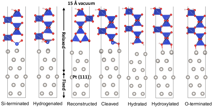
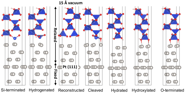
The structure of the membrane was based on the -quartz crystal structure of \ceSiO2, since it is the most stable polymorph of \ceSiO2 Eder et al. (2015). A slab model of the \ceSiO2(001) surface with 6 \ceSiO2 layers was constructed and the positions of all atoms were optimized. The \ceSiO2(001) surface is unstable as cleaved from the bulk crystal structure (Figure 1b) and reconstructs in vacuum (Figure 1a) Chen et al. (2008). In the presence of water, the \ceSiO2(001) surface forms a hydrated reconstruction through the addition of one water molecule per surface unit cell (Figure 1c) Goumans et al. (2007). We considered the exposed \ceSiO2 surface to be generally hydrated, since the coated electrode is submerged in aqueous electrolyte at electrocatalytic conditions.
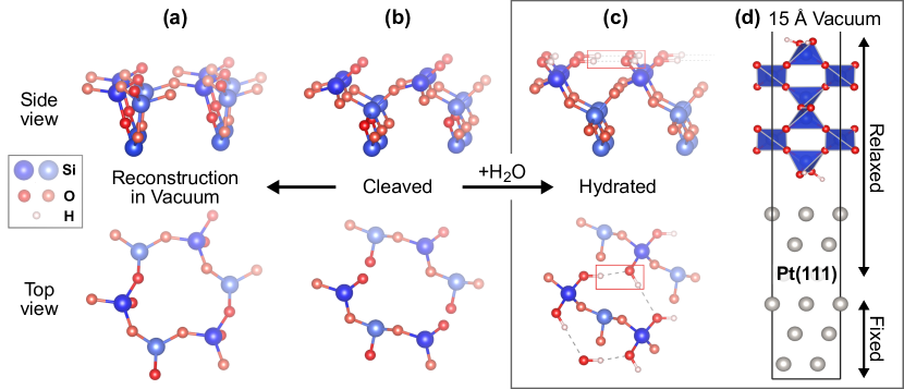
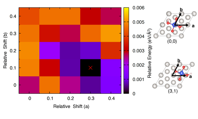
Our \ceSiO2 / Pt interface structure model was constructed by combining the \cePt(111) and \ceSiO2(001) slabs (Figure 1d). Both the \cePt(111) surface and the \ceSiO2(001) surface have hexagonal unit cells, so that an interface structure could be constructed by scaling the and lattice parameters of the \ceSiO2(001) slab model to the dimensions of the \cePt(111) surface unit cell. The lattice mismatch of Å (\cePt) to Å (\ceSiO2) corresponds to 12% tensile strain in the \ceSiO2 membrane. The optimal relative position of the Pt surface and the membrane was first pre-screened using a binding site scan (Figure S1), which was followed by an optimization of the positions of all atoms in the \ceSiO2 membrane and the Pt surface, as described in section II.1. The interface slab model was terminated by a 15 Å wide vacuum region in the direction of the exposed \ceSiO2(001) surface. A representative slab model with hydrated membrane is shown in Figure 1d, and structure files are provided as part of the Supporting Information.
II.3 Interface and surface stability
We introduce three quantities related to different aspects of the stability of interfaces: (i) the adhesion energy, (ii) the detachment energy, and (iii) the interface free energy of formation.
The interface adhesion energy originates from attractive interactions between the Pt surface and the \ceSiO2 membrane
| (1) |
where is the energy of the interface structure as predicted by DFT and and are the DFT energies of the \cePt(111) and \ceSiO2 slabs in isolation.
The adhesion energy needs to be overcome to fully detach the \ceSiO2 membrane from the Pt surface. For reactants to reach the Pt catalyst surface, it is sufficient if the membrane detaches locally from the Pt surface by a few Angstroms depending on the size of the reactant species. The energy required for such partial detachment of the membrane is more intuitively expressed relative to the energy of the intact interface. We therefore define the detachment energy as the energy difference between the interface ground-state structure and a structure in which the membrane has dissociated by a distance from the Pt surface
| (2) |
where and are the DFT energies of the detached and the ground-state interface structures, respectively, and is the cross area of the interface.
Although the adhesion energy may be considered a measure of mechanical stability, it does not quantify the thermodynamic stability of the interface. Instead, the interface free energy of formation has to be considered, which is a function of other thermodynamic variables and is therefore environment-dependent. An approximation to the free energy of formation is derived in the following section.
II.4 Interface Pourbaix diagram formalism
In an electrochemical cell, the encapsulated electrode is submerged in an electrolyte and a potential bias may be applied. Assuming that the \ceSiO2 membrane is permeable for water and protons Miyake and Rolandi (2015); Shan et al. (2019); Jo et al. (2020), in thermodynamic equilibrium, the buried interface is subject to the pH value of the aqueous electrolyte and the applied potential. At the most fundamental level, the thermodynamic stability of a given interface structure is therefore determined by the pH- and potential-dependent free energies of all competing interface structures.
The stability of phases in water as function of the pH value and potential is conventionally characterized by Pourbaix diagrams Pourbaix (1974). Methodologies for calculating Pourbaix diagrams by combining results from DFT and experiment have previously been described Persson et al. (2012); Rong and Kolpak (2015); Artrith et al. (2016). Here, we generalize the concept of computational Pourbaix diagrams to interfaces of (semi-)permeable membranes.
To compare the relative stability of different interface structures with varying oxygen and hydrogen contents at the buried \ceSiO2 / Pt interface, we consider the free energy of reaction of the formal interface formation reaction
| (3) |
where the and are the number of water molecules and proton-electron pairs added (or removed) during the formation of the interface structure. For our specific \ceSiO2 slab model with 6 \ceSiO2 layers (see section II.2), and assuming that the \ceSiO2 surface that is exposed to the aqueous electrolyte is always hydrated, the composition of the \ceSiO2 slab can be explicitly written as \ce6 SiO2 * H2O = \ceSi6H2O13, yielding
| (4) |
where Pt is used as a shorthand for the \cePt(111) slab.
Two assumptions are made by casting all interface compositions \ceSi6H_xO_y / Pt in the form of equation (4). First, we consider only interfaces that can be constructed from the Pt slab and \ceSiO2 slab models described in section II.2. Using different slab models (e.g., with fewer numbers of layers or larger surface unit cells) as reference would change the free energy of reaction (4) by a constant but would not affect relative free energies and relative interface stability. Second, since we are interested only in the nature of the buried interface, we consider the exposed \ceSiO2 surface to be always hydrated, and only variation of H and O atoms at the buried interface is considered. This means, we assume that our membrane structure model is thick enough, so that the termination of the exposed \ceSiO2(001) surface can be expected to be independent of the composition at the buried interface and would therefore not affect the relative stability of different interface compositions.
With reaction (4), the relative Gibbs free energy of formation of a specific interface with composition \ceSi6H_xO_y / Pt is
| (5) |
where denotes the Gibbs free energy of phase , and and are the chemical potentials of protons and electrons, respectively. We note that proton exchange membrane (PEM) electrolyzers operate in acidic conditions (pH 2),ijhe38-2013-4901 the pH value in alkaline electrolyzers is acidic (pH 1–4) at the anode and alkaline (pH 14) at the cathode,pieee100-2012-410 and the pH range for saline water electrolysis is between pH 4–9.Tong et al. (2020) Since the water self-ionization can be neglected over the relevant pH range, the concentration of hydroxide ions (\ceOH^-) is inversely proportional to the \ceH^+ concentration (pOH pH). Therefore, \ceOH^- ions do not occur explicitly in equation (5) irrespective of the pH value of the electrolyte.
At room temperature, the temperature dependence of the free energy of solid and liquid phases is small in comparison to the dependence on the proton and electron chemical potentials (see section 3 of the supporting information), so that we approximate the free energies of the interface structure, the \cePt slab, the \ceSiO2 slab, and water with their respective 0 K enthalpies as approximated by DFT energies:
| (6) |
We recall also that the energies of the \cePt slab and \ceSi6H2O13 are constant terms that do not affect the relative free energies.
The chemical potentials of protons and electrons can be expressed in terms of the pH value and the applied potential , respectively
| (7) |
where is Boltzmann’s constant, and is the temperature. At standard conditions and in equilibrium, the chemical potentials are, further, related to the chemical potential of hydrogen in the gas phase (standard hydrogen electrode)
| (8) |
The measured entropy of hydrogen at standard conditions can be taken from thermochemical tables Chase (1998) and is J K-1 mol eV K-1. To achieve compatibility with our DFT calculations, the enthalpy of hydrogen at standard conditions is approximated by the DFT energy of a hydrogen molecule , which yields
| (9) |
which is also known as the computational standard hydrogen electrode Nørskov et al. (2004).
Inserting the approximation of equations (6) and (9) into the expression of the free energy of formation in equation (5) gives
| (10) | |||
which depends only on DFT energies and the tabulated hydrogen entropy.
Using the expression of the interface free energy of formation in equation (10), interface Pourbaix diagrams can be constructed by determining the lower convex hull of the free energy functions of all relevant interface structures.
| Termination | Composition | Adhesion Energy (eV Å-2) | Distance (Å) |
|---|---|---|---|
| Si-terminated | \ceSi6H2O12 / Pt | 1.82 | |
| Hydrogenated | \ceSi6H3O13 / Pt | 2.24 | |
| Cleaved | \ceSi6H2O13 / Pt | 1.97 | |
| Reconstructed | \ceSi6H2O13 / Pt | 2.83 | |
| Hydrated | \ceSi6H4O14 / Pt | 2.37 | |
| Hydroxylated | \ceSi6H3O14 / Pt | 2.10 | |
| O-terminated | \ceSi6H2O14 / Pt | 1.91 |
III Results
Having developed both structure models (section II.2) and a formalism for the prediction of interface stability (section II.4), we proceed to investigate the properties of the buried \ceSiO2 / Pt interface.
III.1 Binding of the \ceSiO2 membrane to the Pt surface
From experimental characterization it is known that the composition of silica membranes can deviate significantly from the ideal \ceSiO2 and can exhibit different Si:O ratios at the buried interface Mirley and Koberstein (1995). To investigate how the chemical termination of the membrane affects the interactions with the \cePt surface, the termination of the \ceSiO2 membrane at the interface was systematically varied based on the slab model of Figure 1d.
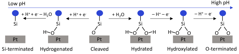
By design, our interface structure model exhibits exactly one \ceSiO4 group per surface unit cell that is in contact with the \cePt surface. Figure 2 shows the different membrane terminations that were derived from the ideal cleaved \ceSiO2 surface and are interrelated by the addition and removal of protons and water molecules. We also considered the reconstruction of the cleaved membrane surface described in Figure 1, which is referred to as reconstructed \ceSiO2 membrane in the following.
The membrane terminations in Figure 2 are sorted in the order of the expected pH dependence based on the number of protons that were formally added or removed to the structures. Hydrogenation of the O atom of the cleaved \ceSiO2 surface creates a silanol (\ceSi-OH) group. Reaction with an additional proton and the removal of an \ceH2O molecule yields a Si-terminated membrane. A hydrated membrane is obtained by reaction with a water molecule, as shown also in Figure 1c. Removal of a proton from the hydrated membrane gives a hydroxylated termination, since it is related to the cleaved \ceSiO2 structure by the formal addition of a hydroxy group. Formally, the simultaneous addition of a water molecule and removal of a proton is equivalent to the addition of a hydroxy group at high pH values. Removal of the remaining proton from the hydroxylated membrane results in a fully O-terminated membrane.
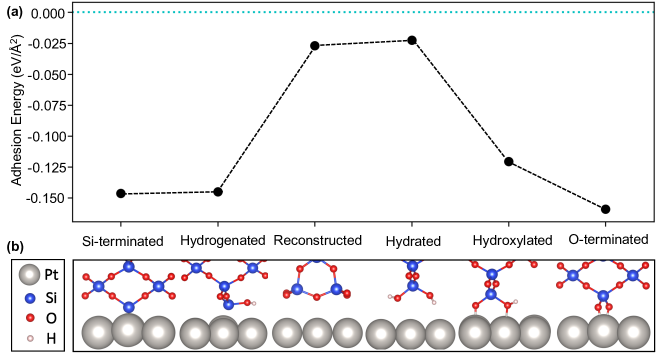
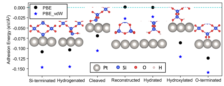
The optimized atomic structures of the different interface terminations along with their respective adhesion energies are shown in Figure 3, and the numeric values of the adhesion energies are listed in Table 1. As seen in Figure 3a, the adhesion energy varies with the interface composition over a range of to eV Å-2. Excerpts from the corresponding atomic structures at the buried interface are seen in Figure 3b, and visualizations of the complete slab model structures are shown in supporting Figures S2 and S3. The reconstructed and hydrated \ceSiO2 membrane terminations show only weak interactions with the \cePt surface, whereas the Si-, O-terminated, and hydrogenated membranes binds strongly with the \cePt surface. The magnitude of the adhesion energy decreases in the order O-terminated Si-terminated hydrogenated hydroxylated reconstructed hydrated.
As seen in supporting Figure S4, the trends are also observed in DFT calculations without van-der-Waals correction, though the adhesion energy of the reconstructed and hydrated membranes with the Pt surface is nearly zero, indicating that these membranes bind mainly via dispersive interactions, and a van-der-Waals correction is indeed needed.
The differences in adhesion energy are also mirrored by variations in the distance between the \cePt surface and the \ceSiO2 membrane. The weakly binding reconstructed and hydrated interfaces show large separations of 2.8 Å and 2.4 Å from the Pt surface, respectively, whereas the distances of the strongly binding Si-terminated and O-terminated membranes are only 1.8 Å and 1.9 Å, respectively. The bond distances found for all interface terminations are listed in Table 1.
A strong binding between the \ceSiO2 membrane and the \cePt surface does not necessarily imply that an interface termination is also thermodynamically stable. As discussed in section II.4, the interface stability is determined by the environment-dependent Gibbs free energy of formation, which we will consider in the following section.
III.2 pH and potential dependence
| Termination | Composition | (eV) |
|---|---|---|
| Si-terminated | \ceSi6H2O12 <=> Si6H2O13 - H2O + 2(H^+ + e^-) | |
| Hydrogenated | \ceSi6H3O13 <=> Si6H2O13 + 1(H^+ + e^-) | |
| Reconstructed | \ceSi6H2O13 <=> Si6H2O13 | |
| Hydrated | \ceSi6H4O14 <=> Si6H2O13+H2O | |
| Hydroxylated | \ceSi6H3O14 <=> Si6H2O13 + H2O - 1(H^+ + e^-) | |
| O-terminated | \ceSi6H2O14 <=> Si6H2O13 + H2O - 2(H^+ + e^-) |
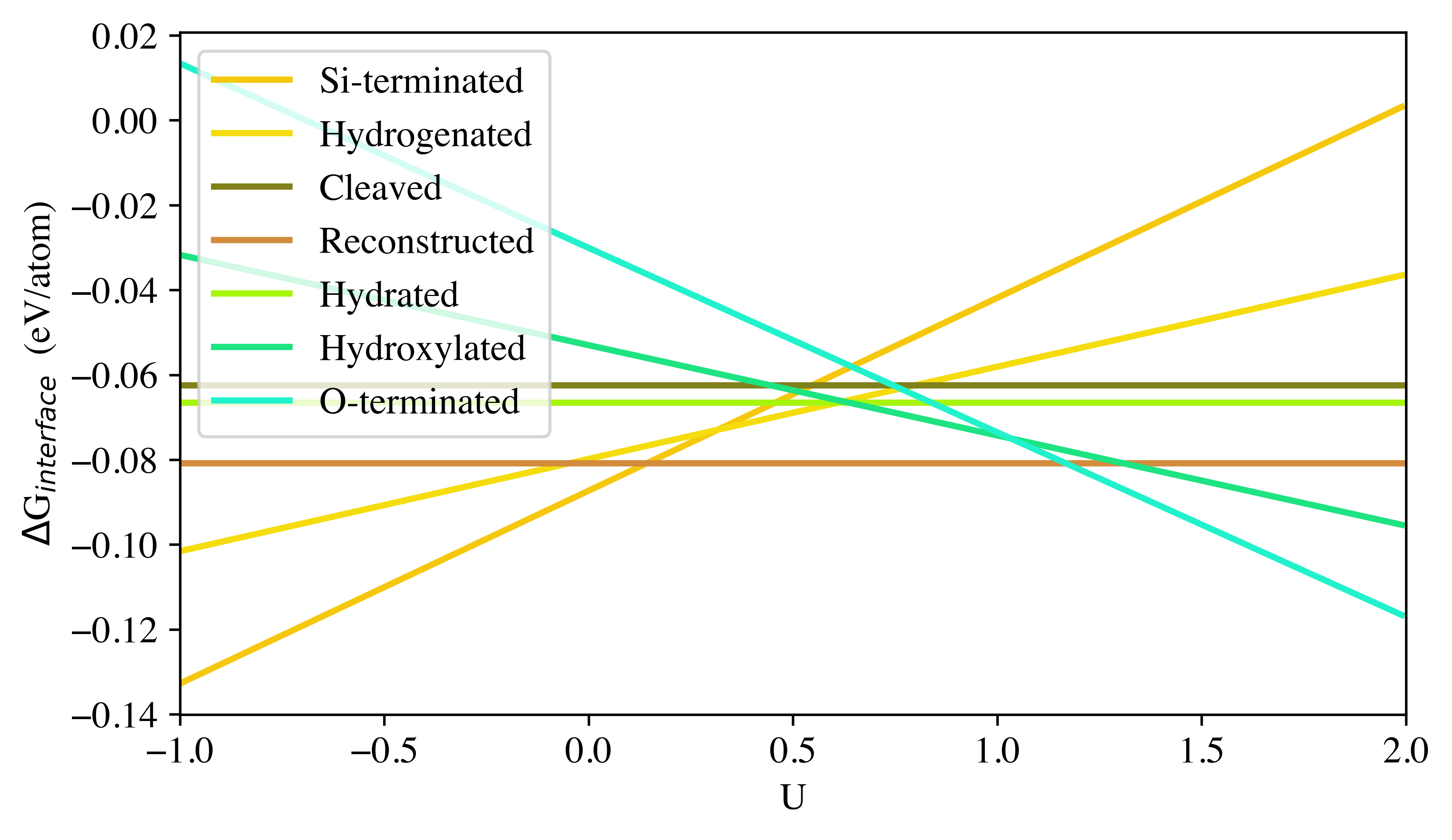
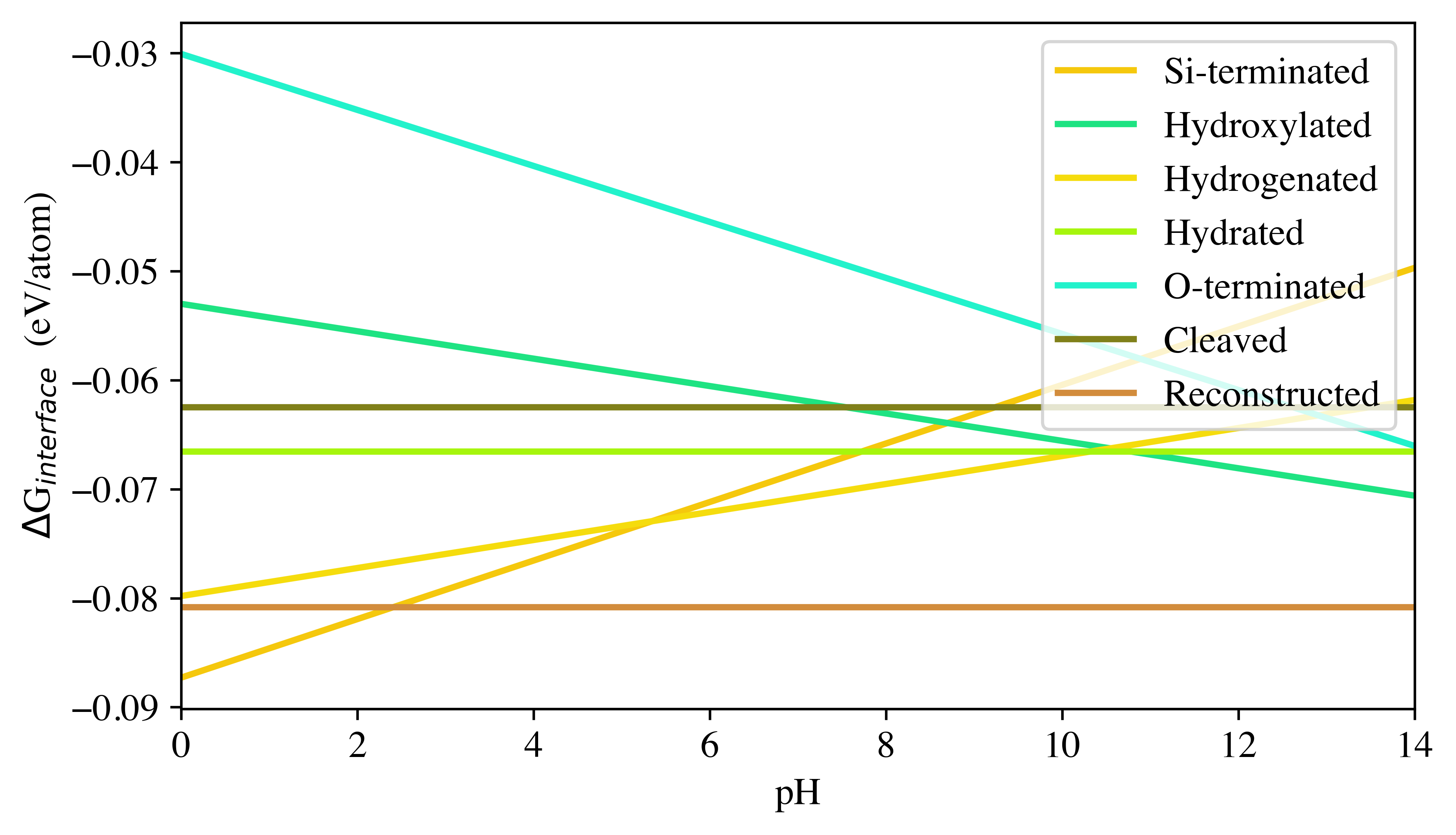
To determine which of the interface terminations of Figure 3 are thermodynamically stable at conditions relevant for electrocatalysis, we applied the interface Pourbaix diagram formalism of section II.4 to the interface structures of Figure 3. Table 2 lists the expressions of the relative interface Gibbs free energies of formation for the different membrane terminations. The free energies of the reconstructed and the hydrated interface show no pH or potential dependence, since they had no protons formally added or removed compared to the pristine \ceSiO2. As noted above, the formal addition of a water molecule and simultaneous removal of a proton-electron pair is equivalent to the addition of a hydroxide ion, hence, hydroxylating the cleaved interface is equivalent to deprotonating the hydrated interface.
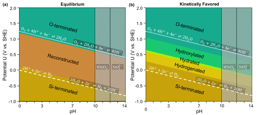
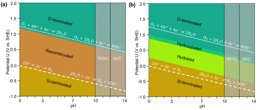
The resulting interface Pourbaix diagram is shown in Figure 4a. Only three of the interface terminations occur in the phase diagram: Irrespective of the pH value, the stable interfaces are (in order of increasing potential) the (1) Si-terminated, (2) reconstructed, and (3) O-terminated membrane structures. The hydrogenated, hydrated, and Hydroxylated membrane structures do not exhibit any stability region in the Pourbaix diagram.
The dashed and dotted lines in Figure 4 indicate the boundaries of the electrochemical stability window of water under equilibrium conditions. All three interface phases are accessible within the water stability range. See also supporting Figures S5–S7 for one-dimensional slices through the Pourbaix diagram for pH=0, pH=7, and =0 V. In absence of an applied potential, the \ceSiO2 membrane is either Si terminated (for pH2) or reconstructed.
SiO2 is known to dissolve in water for pH values above 10 by forming \ceHSiO3^- or (for pH>12) \ceSiO3^2- Pourbaix (1974), so that these pH regions are not accessible with an \ceSiO2-membrane coated Pt electrode. Instead, the O-terminated membrane termination is only formed for positive applied potentials.
Note that the conditions for HER are at negative potentials below the equilibrium potential for water reduction (dashed line), for which the membrane is predicted to be generally Si-terminated in thermodynamic equilibrium. At OER conditions, i.e., at potentials above the water oxidation potential (dotted line), the membrane is predicted to be O-terminated.
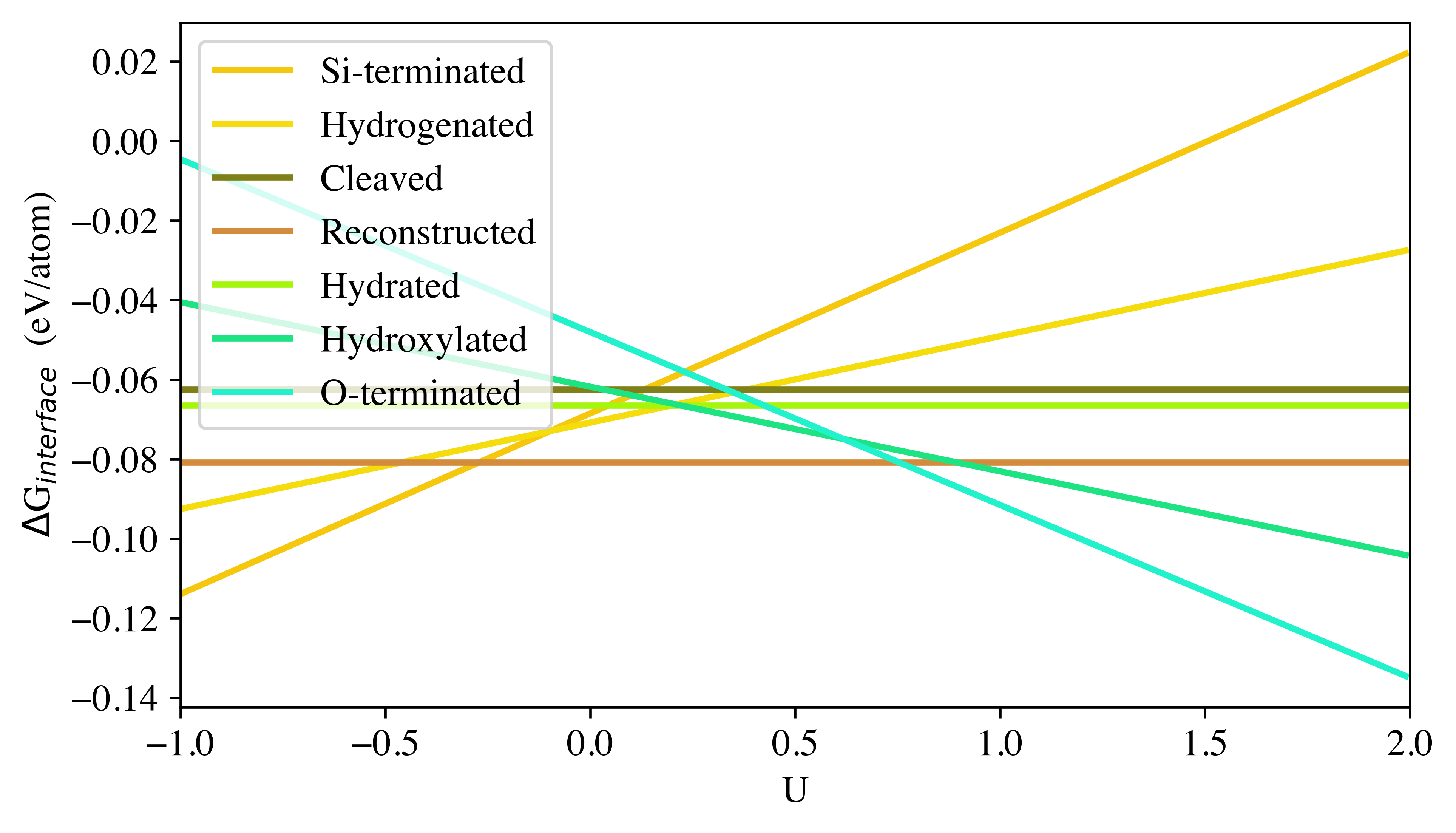
The equilibrium interface Pourbaix diagram of Figure 4a implies that water molecules can permeate through the \ceSiO2 membranes instantaneously and without any kinetic barrier. If the transport of water molecules towards and away from the buried interface is subject to a kinetic activation energy, the addition (removal) of water molecules to (from) the membrane surface would be kinetically hindered. The formation of the reconstructed membrane surface is also likely associated with a kinetic barrier, since the structure of the reconstructed \ceSiO2 surface is substantially different from the other membrane terminations (see also Figure 3b). The Pourbaix diagram in Figure 4b shows the interface phases that are kinetically favored considering water transport and the kinetic limitation of the surface reconstruction, which are derived from the hydrated membrane at high positive potentials (shades of green/blue) and from the unreconstructed cleaved membrane at negative and low positive potentials (shades of brown).
The interface Pourbaix diagrams obtained from DFT calculations without van-der-Waals correction are shown in supporting Figure S8. As seen in the diagrams, the overall trends remain identical to the Pourbaix diagrams of Figure 4, but the size of the stability regions is affected and the hydrogenated membrane termination does not occur in the Pourbaix diagram with kinetically favored phases. This provides further evidence of the importance of van-der-Waals interactions for the correct description of the membrane-catalyst interface.
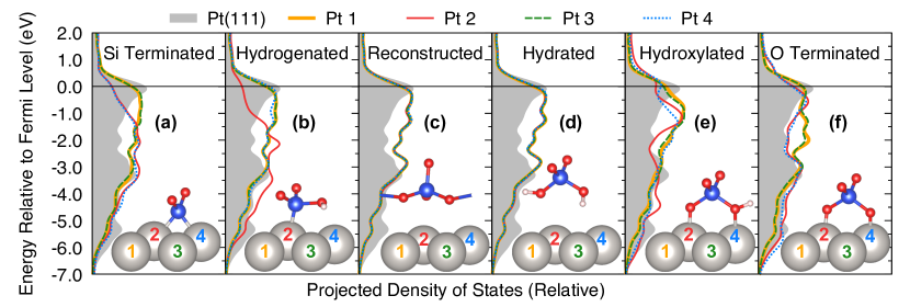
III.3 Charge transfer between the \ceSiO2 membrane and the Pt surface
The interface Pourbaix diagram of Figure 4 shows that the stable phase of the buried \ceSiO2 / Pt interface depends on the pH value and the applied potential. In turn, the amount of charge transfer between the \ceSiO2 membrane and the \cePt surface can also be expected to vary with the prevalent bond at the buried interface. Since the energy of the Pt -band states is intimately connected with the catalytic activity (-band model) Nørskov (1991); Hammer and Norskov (1995), we evaluated the -band projected electronic density of states (PDOS) of the surface Pt atoms for the different membrane terminations.
Figure 5 shows the PDOS of the surface Pt atoms for the different membrane terminations compared to the bare Pt surface, confirming that the \ceSiO2 membrane has a significant impact on the electronic states of the Pt atoms at the buried interface. In the case of the Si-terminated \ceSiO2 membrane (Figure 5a), the valence band DOS near the Fermi level is depressed for the two coordinated surface Pt atoms (Pt 2 and Pt 4), indicating partial oxidation, i.e., the Pt electrode is reducing the membrane. The same is seen for the single coordinated Pt atom (Pt 2) at the hydrogenated interface (Figure 5b). The reconstructed and hydrated \ceSiO2 membrane interacts only weakly with the Pt surface (see also Figure 3), showing no specific impact on any of the surface Pt atoms. However, the valence band states are overall raised. The DOS of the two coordinated Pt atoms (Pt 2 and 4) at the hydroxylated interface (Figure 5c) show an increased valence-band density, indicating charge transfer from the membrane to the Pt surface, i.e., the Pt electrode is slighly oxidizing the membrane. The impact on the DOS of the coordinated Pt atoms (Pt 2 and 4) is least obvious in the case of the O-terminated membrane (Figure 5d).

The Pt surface sites that are directly bonded with atoms in the \ceSiO2 membrane might not be accessible for reactants, but the DOS of the vacant surface sites (Pt atoms 1 and 3 in Figure 5) is also affected. For all interface terminations, the valence-band DOS of the uncoordinated Pt atoms 3 and 4 increases near the Fermi level. To quantify this change in the -band DOS of the uncoordinated surface sites, we calculated the -band center, and the results are compared to surface atoms in bare Pt(111) in Figure 6. As seen in the figure, the -band center is raised by 0.4 to 0.5 eV. The effect is strongest for the hydrogenated, hydrated, and hydroxylated interfaces, though the -band center varies only by 0.1 eV across the four interface terminations. Hence, reactants interacting with the Pt surface at the buried interface are experiencing transition-metal atoms with higher -band center, which generally results in increased binding energies Norskov et al. (2011); Wannakao et al. (2017).
III.4 Towards determining active sites: cavities at the buried interface
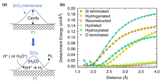
Understanding mechanistically how electrochemical reactions take place at the buried \ceSiO2 / Pt interface would require modeling the interaction of reactants and products with the catalyst surface and the membrane and is thus beyond the scope of the present work. However, a catalytic reaction can only occur at the buried \ceSiO2 / Pt interface if the reactants can access active sites at the surface of the Pt catalyst. Hence, there should exist pockets or cavities at the buried interface that are sufficiently large for the reaction to take place. Based on the interactions between the \ceSiO2 membrane and the \cePt surface determined in the previous sections, we can derive initial insight into the formation of such interface cavities.
The formation of an interface cavity necessarily involves the local detachment of the \ceSiO2 membrane from the Pt surface, a process that is schematically shown in Figure 7a. As an approximate measure of the energy required for cavity formation, we determined the detachment energy as defined in equation (2) for membranes with the four stable terminations.
The energies required for complete detachment are equivalent to the adhesion energies of Table 1, however, complete detachment is not needed to form an interface cavity. The space requirement for the catalytic reaction depends instead on the reactant and product species. Considering the small size of \ceH2 molecules with a bond length of only 0.74 Å, cavities with a diameter of 2 Å could be sufficient for HER. The diameter of a water molecule is about 2.75 Å, so that more space is needed if the reactants or products are dissolved.
Figure 7b shows the detachment energies of membranes with the four different stable terminations as function of the distance from the Pt surface. As seen in the figure, the curvature of the bond curves varies strongly with the membrane termination: The O- and Si-terminated membranes, which bind most strongly to the Pt surface (Table 1), also exhibit the steepest increase in the detachment energy, indicating a stiff bond that might impede the formation of a cavity at the interface. The hydrated and hydrogenated membrane terminations show softer bonds with the Pt surface, allowing the more facile creation of interface cavities. The reconstructed and hydrated membranes bind only via weak interactions with the Pt surface and show the smallest detachment energies.
To give a concrete example, creating a cavity with 3 Å diameter at the O-terminated interface approximately requires an energy of about 0.14 eV/Å2. Even though, the adhesion energy of Si-terminated and hydrogenated membranes is nearly identical (Table 1), the distance of the membranes from the Pt surface and the curvature of the detachment energy are quite different. While Si-terminated membranes bind stiffly with the Pt surface at a distance of around 1.8 Å, the bonding with hydrogenated membranes is softer, and only 0.06 eV/Å2 are required to create a 3 Å cavity. Nearly no energy is required to create 3 Å cavities at the reconstructed and hydrated interfaces.
IV Discussion
In this article, we developed a formalism for the description of semipermeable coatings on electrocatalysts in aqueous electrolyte. We evaluated the impact of the pH value and an applied potential on the interactions between the Pt catalyst surface and a coated \ceSiO2 membrane by extending the concept of Pourbaix diagrams to (permeable) interfaces. The results show that the structure and composition of the buried \ceSiO2 / Pt interface are not static but instead respond to changes in the pH value and the applied potential. Our calculations predict (Figure 4a) that the \ceSiO2 membrane in contact with the Pt surface is Si-terminated for potentials below the water reduction potential. As the potential is increased, the \ceSiO2 membrane preferentially exhibits a reconstruction that is also known to be stable in vacuum and binds only with dispersive interactions to the Pt surface. As the potential for water oxidation is approached, the membrane is preferentially O-terminated, i.e., \ceSi-O^- groups bind to the Pt surface.
Considering kinetic barriers for water transport through the \ceSiO2 membrane and for the formation of the reconstructed \ceSiO2 surface, other interface phases might become accessible (Figure 4b). In the order of increasing potential, the membrane is Si-terminated at negative potentials, then the addition of a proton to the pristine membrane surface (hydrogenation) becomes thermodynamically preferred, so that silanol (\ceSi-OH) groups are formed, then the preferred membrane termination becomes hydroxylated, i.e., exhibits silanol and \ceSi-O^- groups before eventually reaching the O-terminated phase.
The trends predicted by our surface Pourbaix diagram analysis agree largely with chemical intuition. The formation and dissociation of silanol groups \ceSi-O^- + H2O <-> Si-OH + OH^- on the surface of \ceSiO2 in aqueous solution has been well characterized, and silanol groups are known to be present for pH4, i.e., at pH values smaller than the p of \ceSi-OH Ong et al. (1992); Azam et al. (2012). The phase dynamics at the buried interface is, however, more complex than the surface phases of \ceSiO2 alone, since dangling bonds on the membrane surface can be saturated by coordinating with the Pt surface atoms. Cyclic voltammetry characterization of the \ceSiO2 / Pt system has shown evidence of the formation of \cePt-O bonds at positive potentials Robinson et al. (2018), in agreement with our predictions. An experimental confirmation of the existence of \ceSi-Pt bonds at negative voltages should in principle be possible with vibrational spectroscopy, but we are not aware of any published reports that we could compare with.
We note that Pt metal reacts with water at positive potentials above 1.18 V vs. SHE at pH = 0 to form the oxide \cePtO2 Pourbaix (1974). \cePtO2 formation was not considered in our calculations and might occur also at the buried \ceSiO2 / Pt interface. However, at the relevant potentials the formation of \cePtO2 competes with the \cePt-O bonds that are present at the O-terminated interface, so that the \ceSiO2 membrane might have a stabilizing effect on the Pt surface. Further investigation is needed to determine whether Pt oxide formation is likely.
The dynamic changes of the buried interface with pH and potential can be expected to affect catalytic performance. First, the bonding and adhesion of the membrane to the Pt surface controls not only the stability against unwanted detachment but also the accessible catalyst surface area. In an electrocatalytic reaction, the reactants have to be able to reach the surface of the Pt catalyst, which is not possible if the \ceSiO2 membrane binds too tightly to the Pt surface. At pH values and potentials for which the membrane binds strongly with the Pt surface, i.e., with \ceO-Pt bonds (Figure 3) at positive potentials, the creation of interface cavities near the catalyst surface requires more energy and is therefore less likely, thus resulting in a decrease of the accessible surface area. The stiffness of the membrane–catalyst bond additionally determines the flexibility of the buried interface with respect to partial detachment of the \ceSiO2 membrane (Figure 7).
Our calculations predict that cavities at the interface are most likely to form when the \ceSiO2 membrane is either reconstructed or hydrated, i.e., at zero or small potentials and within the thermodynamic stability region of water. We note that the detachment energy is only one factor for the formation of interface cavities, and the mechanical response of the \ceSiO2 membrane upon deformation and, potentially, the interaction with water within the cavities are also needed for a complete picture. If \ceSiO2 membranes are permeable for water, which has not been conclusively determined, once formed, interface cavities might be stabilized by water at the interface. While water is implicitly considered in our formalism, a future study should investigate the impact of explicit water molecules at the buried interface.
Not only the presence but also the size of interface cavities will affect the mechanism of catalytic reactions at the buried Pt surface. Exploiting nanoscale confinement effects has previously been proposed for the reduction of overpotentials for oxygen evolution reaction over \ceRuO2 Doyle et al. (2015). The pH and potential dependence of the membrane detachment energy, together with temperature, might provide control knobs for the optimization of cavity sizes that should be further investigated.
In addition to confinement effects, the \ceSiO2 membrane also affects the electronic structure of the Pt catalyst, as our analysis of the -band DOS exemplifies (Figure 5). The surface Pt atoms that are directly coordinated by membrane atoms are partially oxidized at low potentials, i.e., the membrane is reduced in contact with the Pt electrode consistent with expectations. This charge transfer becomes smaller as the potential increases towards the water oxidation potential. However, irrespective of the membrane termination and potential bias, the -band states of the uncoordinated surface Pt sites that are accessible to reactant species is raised to higher energies compared to the bare Pt(111) surface.
An increase of the -band center by 0.4 eV has previously been shown to lead to a comparable increase in the adsorption energy of small molecules Norskov et al. (2011), which could have a significant impact on the catalytic activity. Considering the volcano plot for HER activity Greeley et al. (2006); Sheng et al. (2013), an increased hydrogen binding energy could take metals that bind hydrogen more weakly than Pt closer to the Sabatier optimum. The \ceSiO2 membrane might therefore play a more important role for the catalytic activity of metals that are less efficient HER catalysts than Pt.
Further differences in the interaction of \ceSiO2 membranes with other transition metals can be expected: depending on the electronegativity (or nobility) of the metal, we expect the interface to be more or less oxidized compared to Pt. For example, a less noble metal such as Cu can be expected to exhibit a stronger preference for oxygen at the interface, i.e., the phase boundary of the Si-terminated membrane in the SiO2/Cu interface Pourbaix diagram should shift to lower pH values and more negative potentials compared to SiO2/Pt. No such differences would be expected for Rh, which has the same Pauling electronegativity as Pt (2.28). Indeed, the adhesion energy of the Si-terminated membrane is lower on \ceCu(111) than on \cePt(111) but nearly identical on \ceRh(111) (Table S2), though the construction of the complete interface Pourbaix diagram will be required to make quantitative statements.
Finally, our approach is based on a number of assumptions that should be considered when comparing with experiment. The calculated surface Pourbaix diagram reflects thermodynamic equilibrium conditions, though it can be expected that there is also a kinetic barrier associated with the transition between different bonds and membrane terminations. One contribution to such barrier is the detachment energy of Figure 7, which indicates that the stiffness of the \ceSi-Pt bond would give rise to an activation energy for the addition of water molecules or \ceOH groups to the membrane surface. Hence, the bonding at the interface is unlikely to change instantaneously with pH and potential adjustments. Additionally, our analysis is based on a homogeneous crystalline \ceSiO2 membrane structure, whereas the coating of actual membrane-coated electrocatalysts is amorphous and may exhibit off-stoichiometries. We expect real-world \ceSiO2 membranes to exhibit a distribution of different bonds with the Pt surface instead of the homogeneous bonding modeled here, but the bond distribution is expected to center around the equilibrium bond predicted by the interface Pourbaix diagram. The direct modeling of amorphous interface structures on the atomic scale, for example using machine-learning techniques Artrith (2019, 2020), is currently an active field of research. However, amorphous \ceSiO2 exhibits the same \ceSiO4 building blocks as the crystalline structure modeled here, so that the chemical properties remain largely unchanged, and any interface bond distributions should therefore be dominated by the thermodynamically most stable bonds identified in the present work.
V Conclusions
Semipermeable silica coatings are promising for the protection of transition-metal electrocatalysts from corrosion and from poisoning by contaminants. We investigated how \ceSiO2 membranes bind to Pt catalyst surfaces and how this interaction affects properties relevant for catalysis. By extending the concept of Pourbaix diagrams to electrochemical solid-solid interfaces of proton-permeable membranes, we determined the stable termination of the \ceSiO2 membrane at the buried interface as a function of the pH value of the electrolyte and the applied potential. Our calculations predict that the thermodynamically preferred membrane termination varies between the potentials for water reduction and oxidation, and the terminating membrane species changes from \ceSi to \ceSi-O as the potential increases. At intermediate potentials, the \ceSiO2 membrane is terminated by a reconstruction and binds only weakly to the Pt surface, unless the formation of the reconstruction is kinetically hindered, in which case \ceSi-OH and \ceSiO-OH groups will bind to the Pt surface. This variation of the membrane termination affects the catalytic properties of the \ceSiO2 / Pt system twofold: (i) through differences in the charge transfer from the Pt surface to the \ceSiO2 membrane that alter the position of the Pt band, and (ii) through changes in the strength and stiffness of the membrane-Pt bonding that control the formation of cavities at the buried interface and the Pt surface area that is accessible by reactant species. Charge transfer between the Pt surface and the \ceSiO2 membrane leads to a general increase in the -band center of the uncoordinated Pt surface atoms, which is expected to increase the binding energy of small molecules compared to the bare \cePt(111) surface. \ceSiO2 membranes are therefore not simply inactive protective coatings but instead participate actively in the electrocatalytic reaction, and the parameters of the combined membrane-coated electrocatalyst are available for tuning the catalytic activity and selectivity. Future studies might investigate how the synergy of an oxide membrane and a metal catalyst can be exploited for the design of better catalysts for specific electrocatalytic processes, such as seawater electrolysis.
Acknowledgments
This work has been partially supported by the Alfred P. Sloan Foundation through grant number G-2020-12650. Computing resources from Columbia University’s Shared Research Computing Facility project are acknowledged, which is supported by NIH Research Facility Improvement Grant 1G20RR030893-01, and associated funds from the New York State Empire State Development, Division of Science Technology and Innovation (NY STAR) Contract C090171, both awarded April 15, 2010. The authors thank Daniel V. Esposito, Marissa E. S. Beatty, and Nongnuch Artrith for insightful discussions.
Appendix A Supporting Information
S1. Supporting Tables
| DFT (This Work) | Experiment | Reference | |
|---|---|---|---|
| \cePt | Å | Å | [77] |
| \ceSiO2 | Å, Å | Å, Å | [78] |
| , | , |
| Metal substrate | Adhesion energy (eV/Å2) |
|---|---|
| \ceSiO2 / Cu(111) | |
| \ceSiO2 / Pt(111) | |
| \ceSiO2 / Rh(111) |
S2. Supporting Figures
S3. Contributions to the interface free energy
The interface Pourbaix diagram formalism introduced in the main manuscript describes the dependence of the interface free energy on the pH value and the electrode potential including the temperature dependence of the standard hydrogen electrode, but it neglects the differences in temperature dependence of the free energy of the solid and liquid phases. Here, we provide a justification for this approximation.
The only liquid phase involved in our calculations is liquid water. However, the term due to the free energy of water is identical in all interface Gibbs free energies of formation, so that any error made in this contribution will only result in a constant energy shift but will not affect any relative quantities that compare different interfaces, such as the Pourbaix diagram. The same argument can be made for the Pt catalyst, which is identical in all interface models. The only component that varies across the interface models is the \ceSiO2 membrane.
Table 2 in the main manuscript gives the Gibbs free energy of interface formation as functions of the pH value and the electrode potential . As seen in the table, the Gibbs energies of four of the interface compositions varies with at least , corresponding to a variation of at least 3 eV for the considered potential range from -1 V to +2 V. The pH dependence is times smaller per pH unit and gives rise to a variation of 0.8 to 1.7 eV for the considered pH range (0 to 14).
To investigate the temperature dependence of free energies, we derive the free energy change when increasing the temperature from 0 K to 298.15 K (room temperature)
| (11) |
where and are the change of enthalpy and internal energy, and and are the energy terms of volume change and entropy change, respectively. Assuming constant pressure in this temperature range yields
| (12) |
where the specific internal energy change from to is neglected. Thus the temperature dependence of the free energy mainly originates from two terms: the volume work and the increase of entropy .
At room temperature, the density of quartz \ceSiO2 is Keiji Kanazawa and Gordon (1985), corresponding to a molar volume of . The volumetric thermal expansion of quartz \ceSiO2 at room temperature compared to 0 K is approximately 0.6% Lager et al. (1982), which corresponds to a volume work of 0.02 J/mol, i.e., a tiny energy difference compared to the pH and potential dependence.
The entropy term is given by the integral , which is 6.36 KJ/mol for \ceSiO2 Piccione et al. (2001). Hence, the free energy decrease of \ceSiO2 owing to the term is at room temperature, a much larger contribution than the term. However, since the various interface structures considered in the main manuscript are mostly identical and differ only by at most 4 atoms in the \ceSiO2 / Pt interface region, the energy differences arising from the entropy term are significantly smaller than the free energy differences due to pH and potential dependence.
References
- Guo et al. (2008) Guo, Y.-G.; Hu, J.-S.; Wan, L.-J. Nanostructured Materials for Electrochemical Energy Conversion and Storage Devices. Adv. Mater. 2008, 20, 2878–2887.
- Gu et al. (2014) Gu, S.; Xu, B.; Yan, Y. Electrochemical Energy Engineering: A New Frontier of Chemical Engineering Innovation. Annu. Rev. Chem. Biomol. Eng. 2014, 5, 429–454.
- Xiao et al. (2015) Xiao, P.; Chen, W.; Wang, X. A Review of Phosphide-Based Materials for Electrocatalytic Hydrogen Evolution. Adv. Energy Mater. 2015, 5, 1500985.
- d’Amore Domenech and Leo (2019) d’Amore Domenech, R.; Leo, T. J. Sustainable Hydrogen Production from Offshore Marine Renewable Farms: Techno-Energetic Insight on Seawater Electrolysis Technologies. ACS Sus. Chem. Eng. 2019, 7, 8006–8022.
- Shi et al. (2017) Shi, W.; Guo, F.; Wang, H.; Guo, S.; Li, H.; Zhou, Y.; Zhu, C.; Liu, Y.; Huang, H.; Mao, B.; Liu, Y.; Kang, Z. New Insight of Water-Splitting Photocatalyst: H2O2-Resistance Poisoning and Photothermal Deactivation in Sub-Micrometer CoO Octahedrons. ACS Appl. Mater. Interfaces 2017, 9, 20585–20593.
- Tong et al. (2020) Tong, W.; Forster, M.; Dionigi, F.; Dresp, S.; Sadeghi Erami, R.; Strasser, P.; Cowan, A. J.; Farràs, P. Electrolysis of Low-Grade and Saline Surface Water. Nat. Energy 2020, 5, 367–377.
- Mirley and Koberstein (1995) Mirley, C. L.; Koberstein, J. T. Preparation of Ultrathin Metal Oxide Films from Langmuir-Blodgett Layers. Langmuir 1995, 11, 2837–2839.
- Brinkmann et al. (2001) Brinkmann, M.; Chan, V. Z.-H.; Thomas, E. L.; Lee, V. Y.; Miller, R. D.; Hadjichristidis, N.; Avgeropoulos, A. Room-Temperature Synthesis of a-SiO2 Thin Films by UV-Assisted Ozonolysis of a Polymer Precursor. Chem. Mater. 2001, 13, 967–972.
- K. Yu et al. (2003) K. Yu, K. M.; Thompsett, D.; Chi Tsang, S. Ultra-Thin Porous Silica Coated Silver–Platinum Alloy Nano-Particle as a New Catalyst Precursor. Chem. Commun. 2003, 0, 1522–1523.
- Takenaka et al. (2007) Takenaka, S.; Matsumori, H.; Nakagawa, K.; Matsune, H.; Tanabe, E.; Kishida, M. Improvement in the Durability of Pt Electrocatalysts by Coverage with Silica Layers. J. Phys. Chem. C 2007, 111, 15133–15136.
- Husin et al. (2013) Husin, H.; Su, W.-N.; Pan, C.-J.; Liu, J.-Y.; Rick, J.; Yang, S.-C.; Chuang, W.-T.; Sheu, H.-S.; Hwang, B.-J. Pd/NiO Core/Shell Nanoparticles on La0.02Na0.98TaO3 Catalyst for Hydrogen Evolution from Water and Aqueous Methanol Solution. Int. J. Hydrogen Energy 2013, 38, 13529–13540.
- Esposito (2018) Esposito, D. V. Membrane-Coated Electrocatalysts—An Alternative Approach To Achieving Stable and Tunable Electrocatalysis. ACS Catal. 2018, 8, 457–465.
- Labrador et al. (2018) Labrador, N. Y.; Songcuan, E. L.; De Silva, C.; Chen, H.; Kurdziel, S. J.; Ramachandran, R. K.; Detavernier, C.; Esposito, D. V. Hydrogen Evolution at the Buried Interface between Pt Thin Films and Silicon Oxide Nanomembranes. ACS Catal. 2018, 8, 1767–1778.
- Jo et al. (2020) Jo, W. J.; Katsoukis, G.; Frei, H. Ultrathin Amorphous Silica Membrane Enhances Proton Transfer across Solid-to-Solid Interfaces of Stacked Metal Oxide Nanolayers While Blocking Oxygen. Adv. Funct. Mater. 2020, 30, 1909262.
- Hong et al. (2015) Hong, J.; Lee, S.; Seo, J.; Pyo, S.; Kim, J.; Lee, T. A Highly Sensitive Hydrogen Sensor with Gas Selectivity Using a PMMA Membrane-Coated Pd Nanoparticle/Single-Layer Graphene Hybrid. ACS Appl. Mater. Interfaces 2015, 7, 3554–3561.
- Chen et al. (2017) Chen, M.; Mao, P.; Qin, Y.; Wang, J.; Xie, B.; Wang, X.; Han, D.; hong Wang, G.; Song, F.; Han, M.; Liu, J.-M.; Wang, G. Response Characteristics of Hydrogen Sensors Based on PMMA-Membrane-Coated Palladium Nanoparticle Films. ACS Appl. Mater. Interfaces 2017, 9, 27193–27201.
- Conway and Bockris (1957) Conway, B. E.; Bockris, J. O. Electrolytic Hydrogen Evolution Kinetics and Its Relation to the Electronic and Adsorptive Properties of the Metal. J. Chem. Phys. 1957, 26, 532–541.
- Lewis et al. (2000) Lewis, F. A.; Kandasamy, K.; Tong, X. Platinum and Palladium-Hydrogen. Solid State Phenom. 2000, 73-75, 207–267.
- Labrador et al. (2016) Labrador, N. Y.; Li, X.; Liu, Y.; Tan, H.; Wang, R.; Koberstein, J. T.; Moffat, T. P.; Esposito, D. V. Enhanced Performance of Si MIS Photocathodes Containing Oxide-Coated Nanoparticle Electrocatalysts. Nano Lett. 2016, 16, 6452–6459.
- Robinson et al. (2018) Robinson, J. E.; Labrador, N. Y.; Chen, H.; Sartor, B. E.; Esposito, D. V. Silicon Oxide-Encapsulated Platinum Thin Films as Highly Active Electrocatalysts for Carbon Monoxide and Methanol Oxidation. ACS Catal. 2018, 8, 11423–11434.
- Bockris and Potter (1952) Bockris, J. O.; Potter, E. C. The Mechanism of the Cathodic Hydrogen Evolution Reaction. J. Electrochem. Soc. 1952, 99, 169–186.
- Haas-Santo et al. (2001) Haas-Santo, K.; Fichtner, M.; Schubert, K. Preparation of Microstructure Compatible Porous Supports by Sol–Gel Synthesis for Catalyst Coatings. Applied Catalysis A: General 2001, 220, 79–92.
- Zou and Zhang (2015) Zou, X.; Zhang, Y. Noble Metal-Free Hydrogen Evolution Catalysts for Water Splitting. Chem. Soc. Rev. 2015, 44, 5148–5180.
- Wang and Ye (2006) Wang, S. Q.; Ye, H. Q. Theoretical Studies of Solid–Solid Interfaces. Curr. Opin. Solid State Mater. Sci. 2006, 10, 26–32.
- Norskov et al. (2011) Norskov, J. K.; Abild-Pedersen, F.; Studt, F.; Bligaard, T. Density functional theory in surface chemistry and catalysis. Proc. Natl. Acad. Sci. U.S.A. 2011, 108, 937–943.
- Skúlason et al. (2007) Skúlason, E.; S. Karlberg, G.; Rossmeisl, J.; Bligaard, T.; Greeley, J.; Jónsson, H.; K. Nørskov, J. Density Functional Theory Calculations for the Hydrogen Evolution Reaction in an Electrochemical Double Layer on the Pt(111) Electrode. Phys. Chem. Chem. Phys. 2007, 9, 3241–3250.
- Ferrin et al. (2012) Ferrin, P.; Kandoi, S.; Nilekar, A. U.; Mavrikakis, M. Hydrogen Adsorption, Absorption and Diffusion on and in Transition Metal Surfaces: A DFT Study. Surf. Sci. 2012, 606, 679–689.
- Wellendorff et al. (2015) Wellendorff, J.; Silbaugh, T. L.; Garcia-Pintos, D.; Nørskov, J. K.; Bligaard, T.; Studt, F.; Campbell, C. T. A Benchmark Database for Adsorption Bond Energies to Transition Metal Surfaces and Comparison to Selected DFT Functionals. Surf. Sci. 2015, 640, 36–44.
- Ammal and Heyden (2010) Ammal, S. C.; Heyden, A. Modeling the Noble Metal/TiO2 (110) Interface with Hybrid DFT Functionals: A Periodic Electrostatic Embedded Cluster Model Study. J. Chem. Phys. 2010, 133, 164703.
- Mehta et al. (2017) Mehta, P.; Greeley, J.; Delgass, W.; Schneider, W. Adsorption Energy Correlations at the Metal-Support Boundary. ACS Catal. 2017, 7, 4707–4715.
- Ewing et al. (2015) Ewing, C. S.; Veser, G.; McCarthy, J. J.; Johnson, J. K.; Lambrecht, D. S. Effect of Support Preparation and Nanoparticle Size on Catalyst–Support Interactions between Pt and Amorphous Silica. J. Phys. Chem. C 2015, 119, 19934–19940.
- Miyazaki et al. (2019) Miyazaki, R.; Nakatani, N.; Levchenko, S. V.; Yokoya, T.; Nakajima, K.; Hara, K.; Fukuoka, A.; Hasegawa, J.-y. DFT Mechanistic Study on the Complete Oxidation of Ethylene by the Silica-Supported Pt Catalyst: C=C Activation via the Ethylene Dioxide Intermediate. J. Phys. Chem. C 2019, 123, 12706–12715.
- Zhou et al. (2016) Zhou, Y.; Chen, W.; Cui, P.; Zeng, J.; Lin, Z.; Kaxiras, E.; Zhang, Z. Enhancing the Hydrogen Activation Reactivity of Nonprecious Metal Substrates via Confined Catalysis Underneath Graphene. Nano Lett. 2016, 16, 6058–6063.
- Fu et al. (2017) Fu, Y.; Rudnev, A. V.; Wiberg, G. K. H.; Arenz, M. Single Graphene Layer on Pt(111) Creates Confined Electrochemical Environment via Selective Ion Transport. Angew. Chem. Int. Ed. 2017, 56, 12883–12887.
- Li et al. (2017) Li, H.; Xiao, J.; Fu, Q.; Bao, X. Confined Catalysis under Two-Dimensional Materials. Proc. Natl. Acad. Sci. U.S.A. 2017, 114, 5930–5934.
- Xiao et al. (2020) Xiao, Y.; Wang, Y.; Bo, S.-H.; Kim, J. C.; Miara, L. J.; Ceder, G. Understanding Interface Stability in Solid-State Batteries. Nat. Rev. Mater. 2020, 5, 105–126.
- Li et al. (2020) Li, Z.; Li, A.; Zhang, H.; Ning, F.; Li, W.; Zangiabadi, A.; Cheng, Q.; Borovilas, J. J.; Chen, Y.; Zhang, H.; Xiao, X.; Ouyang, C.; Huang, X.; Lee, W.-K.; Ge, M.; Chu, Y. S.; Chuan, X.; Yang, Y. Multi-Scale Stabilization of High-Voltage LiCoO2 Enabled by Nanoscale Solid Electrolyte Coating. Energy Storage Mater. 2020, 29, 71–77.
- Richards et al. (2016) Richards, W. D.; Miara, L. J.; Wang, Y.; Kim, J. C.; Ceder, G. Interface Stability in Solid-State Batteries. Chem. Mater. 2016, 28, 266–273.
- Zhu et al. (2016) Zhu, Y.; He, X.; Mo, Y. First principles study on electrochemical and chemical stability of solid electrolyte–electrode interfaces in all-solid-state Li-ion batteries. J. Mater. Chem.A 2016, 4, 3253–3266.
- Xiao et al. (2019) Xiao, Y.; Miara, L. J.; Wang, Y.; Ceder, G. Computational Screening of Cathode Coatings for Solid-State Batteries. Joule 2019, 3, 1252–1275.
- Pourbaix and Burbank (1964) Pourbaix, M.; Burbank, J. Atlas D-Equilibres Electrochimiques. J. Electrochem. Soc. 1964, 111, 14C–15C.
- Kresse and Hafner (1993) Kresse, G.; Hafner, J. Ab Initio Molecular Dynamics for Liquid Metals. Phys. Rev. B 1993, 47, 558–561.
- Kresse and Hafner (1994) Kresse, G.; Hafner, J. Ab Initio Molecular-Dynamics Simulation of the Liquid-Metal–Amorphous-Semiconductor Transition in Germanium. Phys. Rev. B 1994, 49, 14251–14269.
- Kresse and Furthmüller (1996) Kresse, G.; Furthmüller, J. Efficiency of Ab-Initio Total Energy Calculations for Metals and Semiconductors Using a Plane-Wave Basis Set. Comput. Mater. Sci. 1996, 6, 15–50.
- Kresse and Furthmüller (1996) Kresse, G.; Furthmüller, J. Efficient Iterative Schemes for Ab Initio Total-Energy Calculations Using a Plane-Wave Basis Set. Phys. Rev. B 1996, 54, 11169–11186.
- Blöchl (1994) Blöchl, P. E. Projector Augmented-Wave Method. Phys. Rev. B 1994, 50, 17953–17979.
- Kresse and Joubert (1999) Kresse, G.; Joubert, D. From Ultrasoft Pseudopotentials to the Projector Augmented-Wave Method. Phys. Rev. B 1999, 59, 1758–1775.
- Perdew et al. (1996) Perdew, J. P.; Burke, K.; Ernzerhof, M. Generalized Gradient Approximation Made Simple. Phys. Rev. Lett. 1996, 77, 3865–3868.
- Perdew et al. (1997) Perdew, J. P.; Burke, K.; Ernzerhof, M. Generalized Gradient Approximation Made Simple [Phys. Rev. Lett. 77, 3865 (1996)]. Phys. Rev. Lett. 1997, 78, 1396–1396.
- Grimme et al. (2010) Grimme, S.; Antony, J.; Ehrlich, S.; Krieg, H. A consistent and accurate ab initio parametrization of density functional dispersion correction (DFT-D) for the 94 elements H-Pu. J. Chem. Phys. 2010, 132, 154104.
- Grimme et al. (2011) Grimme, S.; Ehrlich, S.; Goerigk, L. Effect of the damping function in dispersion corrected density functional theory. J. Comput. Chem. 2011, 32, 1456–1465.
- Eder et al. (2015) Eder, S. D.; Fladischer, K.; Yeandel, S. R.; Lelarge, A.; Parker, S. C.; Søndergård, E.; Holst, B. A Giant Reconstruction of -Quartz (0001) Interpreted as Three Domains of Nano Dauphine Twins. Sci. Rep. 2015, 5, 14545.
- Chen et al. (2008) Chen, Y.-W.; Cao, C.; Cheng, H.-P. Finding Stable -Quartz (0001) Surface Structures via Simulations. Appl. Phys. Lett. 2008, 93, 181911.
- Goumans et al. (2007) Goumans, T. P. M.; Wander, A.; Brown, W. A.; Catlow, C. R. A. Structure and stability of the (001) -quartz surface. Phys. Chem. Chem. Phys. 2007, 9, 2146–2152.
- Miyake and Rolandi (2015) Miyake, T.; Rolandi, M. Grotthuss mechanisms: from proton transport in proton wires to bioprotonic devices. J. Phys.: Condens. Matter 2015, 28, 023001.
- Shan et al. (2019) Shan, J.; Lei, Z.; Wu, W.; Tan, Y.; Cheng, N.; Sun, X. Highly Active and Durable Ultrasmall Pd Nanocatalyst Encapsulated in Ultrathin Silica Layers by Selective Deposition for Formic Acid Oxidation. ACS Appl. Mater. Interfaces 2019, 11, 43130–43137.
- Pourbaix (1974) Pourbaix, M. Atlas of electrochemical equilibria in aqueous solutions, 2nd ed.; Houston, Tex. : National Association of Corrosion Engineers, 1974.
- Persson et al. (2012) Persson, K. A.; Waldwick, B.; Lazic, P.; Ceder, G. Prediction of Solid-Aqueous Equilibria: Scheme to Combine First-Principles Calculations of Solids with Experimental Aqueous States. Phys. Rev. B 2012, 85, 235438.
- Rong and Kolpak (2015) Rong, X.; Kolpak, A. M. Ab Initio Approach for Prediction of Oxide Surface Structure, Stoichiometry, and Electrocatalytic Activity in Aqueous Solution. J. Phys. Chem. Lett. 2015, 6, 1785–1789.
- Artrith et al. (2016) Artrith, N.; Sailuam, W.; Limpijumnong, S.; Kolpak, A. M. Reduced overpotentials for electrocatalytic water splitting over Fe- and Ni-modified BaTiO3. Phys. Chem. Chem. Phys. 2016, 18, 29561–29570.
- (61) Carmo, M.; Fritz, D. L.; Mergel, J.; Stolten, D. A comprehensive review on PEM water electrolysis. Int. J. Hydrog. Energy 2013, 38, 4901–4934.
- (62) Ursua, A.; Gandia, L. M.; Sanchis, P. Hydrogen Production From Water Electrolysis: Current Status and Future Trends. Proc. IEEE 2012, 100, 410–426.
- Chase (1998) Chase, M. W. NIST-JANAF Thermochemical Tables, 4th Edition. 1998,
- Nørskov et al. (2004) Nørskov, J. K.; Rossmeisl, J.; Logadottir, A.; Lindqvist, L.; Kitchin, J. R.; Bligaard, T.; Jónsson, H. Origin of the Overpotential for Oxygen Reduction at a Fuel-Cell Cathode. J. Phys. Chem. B 2004, 108, 17886–17892.
- Mirley and Koberstein (1995) Mirley, C. L.; Koberstein, J. T. A Room Temperature Method for the Preparation of Ultrathin SiOx Films from Langmuir-Blodgett Layers. Langmuir 1995, 11, 1049–1052.
- Nørskov (1991) Nørskov, J. Electronic factors in catalysis. Prog. Surf. Sci. 1991, 38, 103–144.
- Hammer and Norskov (1995) Hammer, B.; Norskov, J. K. Why gold is the noblest of all the metals. Nature 1995, 376, 238–240.
- Norskov et al. (2011) Norskov, J. K.; Abild-Pedersen, F.; Studt, F.; Bligaard, T. Density functional theory in surface chemistry and catalysis. Proc. Natl. Acad. Sci. U.S.A. 2011, 108, 937–943.
- Wannakao et al. (2017) Wannakao, S.; Artrith, N.; Limtrakul, J.; Kolpak, A. M. Catalytic Activity and Product Selectivity Trends for Carbon Dioxide Electroreduction on Transition Metal-Coated Tungsten Carbides. J. Phys. Chem. C 2017, 121, 20306–20314.
- Ong et al. (1992) Ong, S.; Zhao, X.; Eisenthal, K. B. Polarization of Water Molecules at a Charged Interface: Second Harmonic Studies of the Silica/Water Interface. Chem. Phys. Lett. 1992, 191, 327–335.
- Azam et al. (2012) Azam, M. S.; Weeraman, C. N.; Gibbs-Davis, J. M. Specific Cation Effects on the Bimodal Acid–Base Behavior of the Silica/Water Interface. J. Phys. Chem. Lett. 2012, 3, 1269–1274.
- Doyle et al. (2015) Doyle, A. D.; Montoya, J. H.; Vojvodic, A. Improving Oxygen Electrochemistry through Nanoscopic Confinement. ChemCatChem 2015, 7, 738–742.
- Greeley et al. (2006) Greeley, J.; Jaramillo, T. F.; Bonde, J.; Chorkendorff, I.; Nørskov, J. K. Computational high-throughput screening of electrocatalytic materials for hydrogen evolution. Nat. Mater. 2006, 5, 909–913.
- Sheng et al. (2013) Sheng, W.; Myint, M.; Chen, J. G.; Yan, Y. Correlating the hydrogen evolution reaction activity in alkaline electrolytes with the hydrogen binding energy on monometallic surfaces. Energy Env. Sci. 2013, 6, 1509–1512.
- Artrith (2019) Artrith, N. Machine learning for the modeling of interfaces in energy storage and conversion materials. J. Phys. Energy 2019, 1, 032002.
- Artrith (2020) Artrith, N.; Lin, Z.; Chen, J. G. Predicting the Activity and Selectivity of Bimetallic Metal Catalysts for Ethanol Reforming using Machine Learning. ACS Catal. 2020, 10, 9438–9444.
- Jiang et al. (2005) Jiang, L.; Sun, G.; Sun, S.; Liu, J.; Tang, S.; Li, H.; Zhou, B.; Xin, Q. Structure and Chemical Composition of Supported Pt–Sn Electrocatalysts for Ethanol Oxidation. Electrochimica Acta 2005, 50, 5384–5389.
- Hazen et al. (1989) Hazen, R. M.; Finger, L. W.; Hemley, R. J.; Mao, H. K. High-Pressure Crystal Chemistry and Amorphization of -Quartz. Solid State Communications 1989, 72, 507–511.
- Keiji Kanazawa and Gordon (1985) Keiji Kanazawa, K.; Gordon, J. G. The Oscillation Frequency of a Quartz Resonator in Contact with Liquid. Analytica Chimica Acta 1985, 175, 99–105.
- Lager et al. (1982) Lager, G. A.; Jorgensen, J. D.; Rotella, F. J. Crystal structure and thermal expansion of -quartz SiO2at low temperatures. J. Appl. Phys. 1982, 53, 6751–6756.
- Piccione et al. (2001) Piccione, P. M.; Woodfield, B. F.; Boerio-Goates, J.; Navrotsky, A.; Davis, M. E. Entropy of Pure-Silica Molecular Sieves. J. Phys. Chem. B 2001, 105, 6025–6030.