Further author information:
E-Mail: daniel.flamm@trumpf.com.
Beam shaping for ultrafast materials processing
Abstract
The remarkable temporal properties of ultra-short pulsed lasers in combination with novel beam shaping concepts enable the development of completely new material processing strategies. We demonstrate the benefit of employing focus distributions being tailored in all three spatial dimensions. As example advanced Bessel-like beam profiles, 3D-beam splitting concepts and flat-top focus distributions are used to achieve high-quality and efficient results for cutting, welding and drilling applications. Spatial and temporal in situ diagnostics is employed to analyze light-matter interaction and, in combination with flexible digital-holographic beam shaping techniques, to find the optimal beam shape for the respective laser application.
keywords:
Beam shaping, ultrafast optics, laser materials processing, digital holography, structured light1 INTRODUCTION
16cm(2.67cm,1cm) Daniel Flamm, Daniel Günther Grossmann, Michael Jenne, Felix
Zimmermann, Jonas Kleiner, Myriam Kaiser, Julian Hellstern, Christoph
Tillkorn, Malte Kumkar, ”Beam shaping for
ultrafast materials processing,”
Proc. SPIE 10904, Laser Resonators, Microresonators, and Beam Control
XXI, 109041G (4 March 2019); https://doi.org/10.1117/12.2511516
5cm(9.2cm,1.9cm) Invited Paper
17cm(2.25cm,25.25cm)
© 2019 Society of Photo‑Optical Instrumentation Engineers (SPIE). One print or electronic copy may be made for personal use only. Systematic reproduction and distribution, duplication of any material in this publication for a fee or for commercial purposes, and modification of the contents of the publication are prohibited.
Laser Resonators, Microresonators, and Beam Control XXI, edited by Alexis V. Kudryashov, Alan H. Paxton,
Vladimir S. Ilchenko, Proc. of SPIE Vol. 10904, 109041G. © 2019 SPIE. https://doi.org/10.1117/12.2511516
The extreme peak intensities of ultrashort laser pulses lead to linear and non-linear interaction processes with almost all conceivable materials[1, 2, 3]. These remarkable temporal laser properties in combination with tailored spatial focus distributions enable the development of completely new material processing strategies or the optimization of existing ones. The processing of transparent materials[4, 5, 6] – as a particularly attractive and challenging example – has become a topic of late, driven by the need for, e.g., efficient machining of display and cover glasses for consumer electronics with increasingly complex geometries[7, 8, 9]. This requires a controlled energy deposition at the surface or inside the processing volume and, thus, beam shaping concepts in all three spatial dimensions[10, 7, 11, 9]. Although demonstrated in the following for selected examples, the potential for structured light concepts shown here is much greater and could not only be employed for a diversity of ultrafast materials processing strategies but also for applications based on continuous-wave lasers, working in spatial single- or multi-mode regime.
In this paper we present three beam shaping concepts and their implementation into industrial materials processing strategies. Starting with the versatile digital-holographic generation of Bessel-like beams exhibiting adapted transverse and longitudinal focus properties we apply sensitive aberration-correction for full thickness, single pass cleaving of glass with thicknesses of up to . Here, vertical glass edges are demonstrated as well as edges of arbitrary shape.
In order to completely utilize the available high average powers (several ) and pulse energies (several ) of today’s industrial ultrafast laser sources[12] and, thus, to offer attractive industrial applications, diffractive 3D-beam splitting approaches are presented as second beam shaping concept. This allows to arbitrarily distribute a high number of single foci with individual shape and power at the surface or within the volume of the workpiece and, for example, to increase melting rates for glass welding applications.
Finally, we discuss the digital-holographic generation of flat-top beam profiles for ultrafast micron-scaled ablation, drilling and marking of solids and present processing results of high-spatial frequency masks in thin metal sheets with tailored drilling geometries and taper angles.
For processing of transparent materials, advanced spatial and temporal in situ diagnostics is employed to unveil the fundamentals of light-matter interaction and, in combination with flexible digital-holographic beam shaping techniques, to find the optimal beam shape for the respective laser application. Finally, the high quality of presented beam shaping concepts is proven by implementing the optical concepts into successful laser machining processes. In short, the present work demonstrates the enormous benefits of using structured light concepts[13] for industrial ultrafast laser application processes.
We would like to address at this point that pulse durations of employed ultrafast laser sources (TruMicro series 2000 and 5000) are always greater than (resulting spectral width at ) and therefore concepts for the compensation of chromatic aberrations are not necessary, yet (at the applied spatial frequencies). Owing to these (comparatively) long pulse durations, we will also not yet focus on simultaneous spatial and temporal focusing concepts (SSTF)[14, 15].
The paper is organized as follows. In Sec. 2 theoretical concepts are introduced and ultrafast processing experiments are conducted based on the use of Bessel-like beams. The realization and potential applications of ultrafast 3D-focus distributions are discussed in Sec. 3. Finally, Sec. 4 treats the concepts of flexible digital-holographic marking and drilling.
2 Ultrafast Bessel-like Beams
The class of Gaussian beams represent stable solutions of classical resonators and therefore undoubtedly form the most famous class of spatial laser radiation. Directly behind them, however, there are probably Bessel-like beams. The areas of application for this beam concept are enormously diverse ranging from atom trapping and particle manipulation[16, 17] to different materials processing strategies[18, 19].
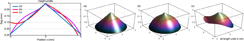
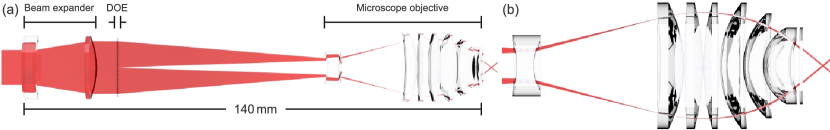
The first Bessel-like beams were generated by ring-slit apertures (far-field generation)[20]. However, for efficiency reasons, the axicon-based generation (near-field)[21] is preferred. An axicon is a conically ground lens, see Fig. 1 (a) and, by design, completely defined by axicon angle 111The widely spread axicon angle definition is used where , with axicon apex angle , see, e.g., McGloin and Dholakia[21]. and refractive index .
If illuminated by a plane wave (of constant amplitude and phase) with a sufficient degree of coherence, a special interference pattern will be observed starting directly behind the axicon tip that is characterized by an elongated intensity maximum on the optical axis surrounded by weaker, equally spaced rings – a so-called Bessel-like beam. The peak intensity ratio of the first ring to the central maximum is about and, thus, particularly favorable for nonlinear absorption processes.222Usually, this ratio is increased significantly, if modified Bessel-like beams are considered [cf. Fig. 3 (b)–(i)]. This interference pattern is a consequence of field components propagating along a cone towards the optical axis with refraction angle and radial component of the wavevector , respectively (in thin-element approximation)[21, 24]. The resulting central core spot size of the fundamental Bessel beam then reads as [21]. Illuminating the axicon with a plane wave of radius allows to approximate the resulting beam length according to [21]. With the last two equations it is easy to estimate that the aspect ratio of longitudinal to transverse dimensions could easily reach factors of higher than , see, e.g. Fig. 3 (a) – one of several outstanding properties of this beam class. Further should only be mentioned here in brief: non-diffracting[20], self-healing[21], simple and efficient generation[21] and – particular interesting for the processing of transparent materials – a natural resistance to spherical aberrations[9].
Despite noteworthy progress in fabrication technology for aspheres or free-form lenses [25, 26] allowing to realize examples shown in Fig. 1 (b) and (c) we will focus on the diffractive realization for the following reason. Elements for phase modulation are required which imprint phase jumps or singularities to the illuminating optical field. Corresponding free-form lenses would neither be continuous nor differentiable and, thus, difficult to manufacture. We therefore review the diffractive realization (Sec. 2.1) and present degrees of freedom for arbitrary Bessel-like beam shaping in three spatial dimensions by applying a single-element approach. Further, we proof that outstanding beam properties can actually be used to control the deposition of energy in the volume of the workpiece (Sec. 2.2) and discuss glass cutting processing results (Sec. 2.3). Finally, the implementation of the optical concepts into an industrial cleaving optics is demonstrated (Sec. 2.4).
2.1 Diffractive Beam Shaping Concept
Various grating concepts are conceivable for the generation of Bessel-like beams. However, for efficiency-reasons we focus on blazed phase-only gratings theoretically reaching diffraction efficiencies of . A radial symmetric transmission according to
| (1) |
acts as axicon hologram[24] [see also Fig. 4 (a)] with the above defined radial component of the wavevector . By this definition a refractive axicon can be assigned directly to its holographic counterpart.333A discussion on fundamental differences between diffractive and refractive axicons is provided by Leach et al.[24].
Refractive or reflective axicons have already been demonstrated with axicon angles of [27]. The diffractive realization of such high axicon angles, however, would be associated with enormous fabrication efforts since already results in grating periods of at which would require grey-tone electron-beam lithography for high diffraction efficiencies. By means of less expensive grey-tone laser-beam lithographic techniques -values of ( at ) can be reached. Liquid-crystal-on-silicon based spatial light modulators (SLMs) with pixels of pitch are able to display digital axicons with angles up to . However, these axicons with low -values connected to the diffractive concepts can be increased virtually using simple telescopic setups[28, 29] limited by the available NA of microscope objectives, see also Secs. 2.3 and 2.4.
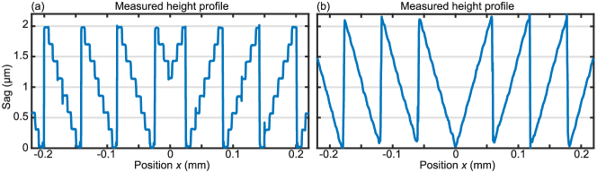
In the following experiments various Bessel-like beams have been generated using either flexible SLMs or diffractive optical elements (DOEs) fabricated via lithography. The desired phase modulation is realized by spatially setting optical path differences . In case of using SLMs this is done electro-optically by controlling the birefringence of the liquid crystals and, thus, and in case of using DOEs, on the other hand, by an etched height profile in fused silica. The measured height profile of two diffractive axicons with stated efficiencies are depicted in Fig. 2.
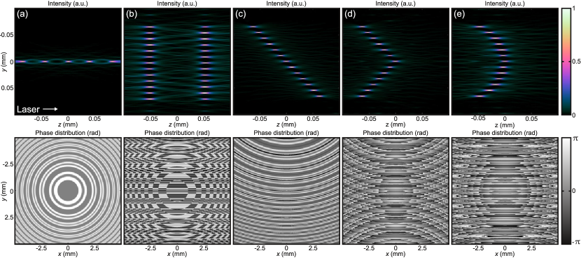
Apart from such advantages as flexibility[11] or the avoidance of round axicon tips[28], diffractive and/or digital holographic techniques are characterized in particular by a large number of degrees of freedom in tailoring the three-dimensional propagation behavior of Bessel-like beams. This plethora of beam shaping possibilities is demonstrated in Fig. 3 (without claiming completeness) where the propagation behavior and corresponding intensity cross section of the fundamental Bessel-Gaussian beam [(a)] can be compared to several Bessel-like solutions exhibiting adapted intensity distributions in longitudinal and transverse direction [(b)–(i)].
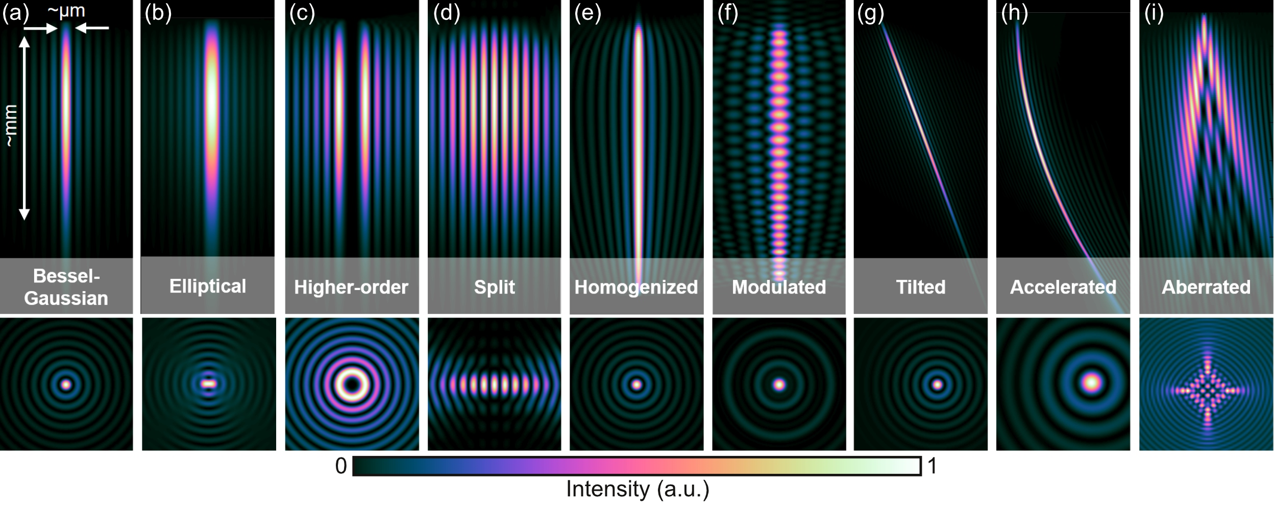
Simple modifications of the axicon-generating phase mask [cf. Fig. 4] allow to realize elongated focus distributions with elliptical central spots[35] [(b)] as well as parallel-running split beams[31] [(d)], Bessel-like beams exhibiting longitudinal homogenization[22] [(e)] or modulation[32] [(f)], and propagating along tilted [(g)][36] or accelerating trajectories [(h)][33].
2.2 Bessel-like Beams of Higher-order
In the following we discuss in detail the diffractive generation of Bessel-like beams of higher-order [cf. Fig. 3 (c)]. One way to realize such is to start with the axicon transmission function of Eq. (1) and to multiplex superpositions of azimuthal phase components
| (2) |
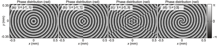
The resulting transmission functions for generating Bessel-like beams of different order with corresponding hellicity indices are depicted in Fig. 4.
Although the transverse intensity profile of higher-order Bessel-like beams completely differ from the zero order version, the above mentioned remarkable properties of this beam class remain intact. Ring profiles with controllable diameters [c.f. Fig. 3 (c)] are as possible as the generation of petal beams and those with a certain preferred direction[11, 38, 37]. Such intensity distributions/beam shaping approaches show promising prospects for material modifications and processing, e.g., the precise cutting of glass [11, 39, 35] by making targeted use of crack formations[31, 40].
We verify excellent suitability of this class of beams for transparent materials processing using a time resolved tomographic imaging concept, see Bergner et al.[11], which allows to reconstruct the three-dimensional spatial distribution of the transient extinction coefficient .444Typically, using transverse pump-probe microscopy there is access to the optical depth from recording shadowgraph images and corresponding background signals [41]. Considering Lambert-Beer’s law, the optical depth represents the integral over the local extinction coefficient along a certain direction, e.g., -axis: [41, 11].
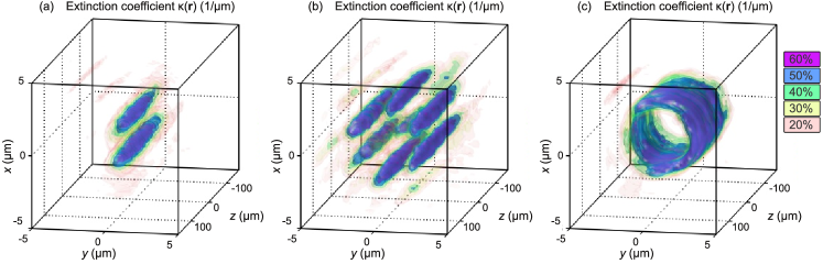
This enables to directly measure the material’s absorbing response555The interaction between ultrashort pulses and matter is a notoriously complex process that will not be further explained in this work, please see, e.g., Itoh et al.[42] or Rethfeld et al. [43] and references therein. caused by the ultrashort pulse and, thus, to analyze where energy was deposited. Results of this investigation are shown in the isosurface representation of Fig. 5 where the extinction coefficient is reconstructed after focusing higher-order Bessel-Gaussian beams into Gorilla glass[11]. Figure 5 (a) shows an elongated -distribution of a few hundred length exhibiting two distinct maxima of distance . In the second case [(b)], the reconstructed extinction distribution reveals an elongated behavior with six parallel running petals distributed point-symmetrically around the optical axis. Finally, Fig. 5 (c), shows an absorption zone of hollow cylindrical symmetry exhibiting diameter and a few hundred length. We conclude that the spatial distribution of the non-linear absorbing response strongly resembles the linear intensity distribution of the corresponding higher-order Bessel-like beam [first-order, petal-like in (a), third-order, petal like (b) and third-order, pure in (c)]. The reason for this can be found in the remarkable self-healing properties of Bessel-like beams which holds for their higher-order versions as well.666Please note, that the absorption behavior will be completely different if ultrashort Gaussian beams are focused into transparent materials, due to the lack of self-healing, see Grossmann et al.[41] or Sec. 3.2, respectively.
2.3 Glass Cutting Using Aberration-corrected Bessel-like Beams
The usage of diffractive optical concepts for the correction of potentially aberrated Bessel-like beams is discussed in the following. In particular, there are aberrations of interest that may occur when propagating through optical interfaces, such as tilted or cylindrical glass surfaces, to cleave transparent materials, e.g., with tailored edges [9]. Resulting phase distortions usually yield a characteristic interference pattern with high intensities no longer confined to the optical axis, as can be seen in Fig. 3 (i), accompanied by a tremendous loss of peak intensity, prohibiting a successful material modification process. It is our aim to precompensate phase deviations by diffractive or digital holographic approaches and to restore the original Bessel-like focus distribution [cf. Fig. 3 (a)].
Our design concept makes use of the aforementioned diffractive Bessel-like beam generation (Sec. 2.1) in combination with a -setup (telescopic demagnification of ). Thus, the axicon is placed virtually onto the optical interface – now with increased axicon angle . As an example we discuss in the following the situation behind tilted plane interfaces[9]. However, the procedure is straight forward for arbitrarily shaped surfaces.
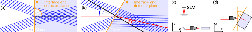
Figure 6 shows a geometric-optical representation of an incident Bessel-like beam for perpendicular [(a)] and tilted [(b)] illumination. For the first case, at the interface between the two media, all radial field components exhibit the same absolute angle of incidence value and propagate identical optical path lengths until they interfere constructively to the desired elongated focus. Considering the scenario of a tilted glass surface, the spatially varying angles of refraction determined by Snell’s law will break the radial symmetry and, depending on the tilt angle, will result in an interference pattern along the geometric focus zone [Fig. 3 (i)].[9]
For further analyzing the problem at hand more quantitatively, we use VirtualLab Fusion [44] providing access to the optical field behind the tilted interface, see Fig. 6 (c) and (d). For this purpose, field-detectors are virtually placed in the plane of the glass surface for normal incidence, see Fig. 6 (a), and in the plane perpendicular to the refraction angle for tilted incidence, see (b), respectively. Knowledge about the aberrated optical field in the plane of the interface enables to calculate deviations from the undisturbed field generating the ideal Bessel-like beam. Due to small differences for the respective Fresnel transmission coefficients we assume and focus on deviations of the corresponding phase distributions . Results of these simulations are depicted in Fig. 7 (a)–(c), where is plotted as an example for three different tilt angles defined within a circle of radius .
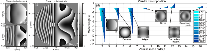
As expected, phase aberrations are growing for increasing values of [Fig. 6 (a)–(c)]. This is illustrated more clearly in Fig. 7 (d) where we perform a decomposition into a set of Zernike modes of order (normalized and indexed according to Noll [45]) using [46]. The graph shows weights of coefficients for different tilt angles. Characteristic for the problem at hand is the continuous growth of certain coefficients with increasing such as (defocus), (oblique astigmatism) or (vertical secondary astigmatism).[9]
As already described earlier, our processing optic design consists of the SLM or DOE, respectively, and a -setup, see Fig. 6 (c). This arrangement allows for both Bessel-like beam generation and compensation of occurring aberrations using a single digital hologram or DOE. For this purpose, the calculated phase aberrations are inverted, the spatial scaling is adapted to the magnification and the resulting transmission is multiplexed with the axicon hologram . Then, the final phase-only hologram reads as , now defined on a magnified circle of radius , for our particular case.[9]
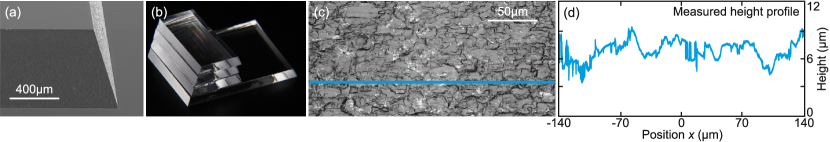
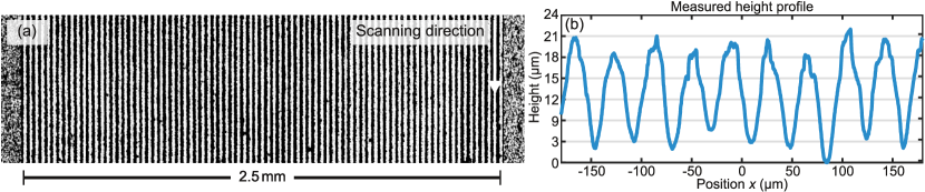
To demonstrate the applicability of our approach, we integrated the resurrected features of the corrected Bessel-like beams into a cleaving process. The employed processing laser was a disk-laser (TruMicro Series 5000) in order to process glasses with thicknesses of (SCHOTT borofloat 33). Here we report on a single pass edge cleaving laser application with inside the material, cf. Fig. 8 (a),(b). We use a spatial pulse distance of at a processing speed of combined with a pulse train configuration (burst) consisting of four pulses with a temporal delay of between each consecutive pulses, pulse duration of and a pulse train energy of approximately . Figure 8(a) shows a scanning electron microscope image of two cleaved glass edges and reveals the precise and defined edge quality for all inclined edges on the thick glass sample. One exemplary image of the surface quality created with a laser scanning microscope and one corresponding line plot is depicted in Fig. 8 (c) and (d), respectively. The arithmetic mean roughness for this process is and absolute vertical height offset .[9]
2.4 Implementation into an Industrial Cleaving Optics
The optical concepts discussed in the previous sections have been incorporated into the development of an industrial processing optics, known as TOP Cleave cutting optics[47]. In the near future, the second generation will be available with outstanding specifications presented in the following.
The new, modular optical concept in combination with the corresponding TruMicro laser platform[48] allows transparent materials of thicknesses between and to be modified and cut, respectively. At the same time, the design of this processing optics is characterized by being particularly compact, light and robust and, thus, can be subjected to high accelerations (). The modular concept also allows extensions with an axis for adjustment of focus position, a swivel axis or bending mirrors. There will be TOP Cleave versions optimized for use with the TruMicro Series 2000 and 5000 laser sources for infrared () and green () wavelength to cut colored glasses, such as infrared filter glasses, additionally. The patented optical concept[29, 35, 49] is based on a diffractive optical element for Bessel-like beam generation and adapted microscope objectives for the mid-NA region of up to . Additionally, in designing these objectives, particular emphasis was placed on achieving a long working distance. Finally, it should be noted, that the optic is compatible with all Bessel-like solutions presented in Fig. 3, thus, also special glasses can be processed with customized geometries, with e.g., bevels or tailored edges, cf. Figs. 3 (g) and 8, respectively. Specifications are summarized in Table 1. Please note, that dimensions and mass indicated here hold for the smallest possible version which enables material modifications of thicknesses up to .
The geometric-optical representation of the light path within a high-NA TOP Cleave version is depicted as an example in Fig. 9. After the beam expansion light passes the central beam shaping element generating a virtual Bessel-like beam profile. Using an adapted microscope objective a real Bessel-like beam is formed with demagnification and desired focus length.
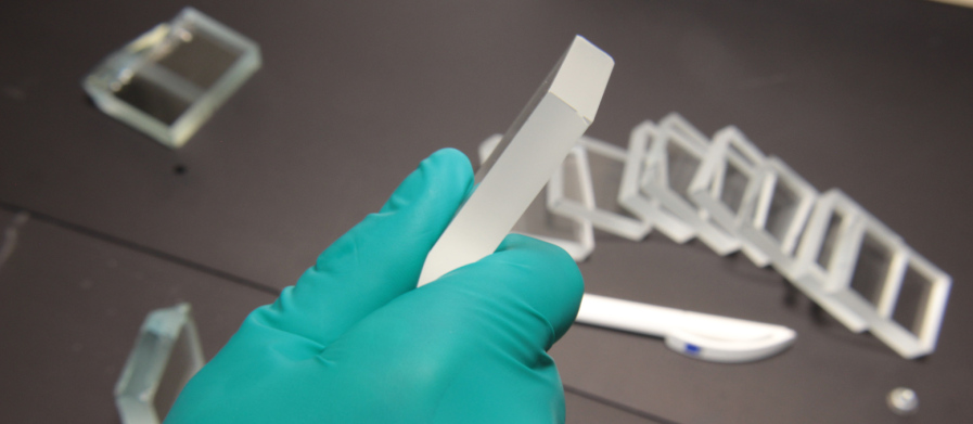
A remarkable example of a successful glass cutting process can be seen in Fig. 10. Here, soda-lime glass of thickness was modified in a single-pass using TOP Cleave and a TruMicro Series 5000 laser emitting ultrashort pulses of energy (available in the near future). The glass cutting was achieved by inducing mechanical stress using cut-running pliers. To the best of our knowledge, using a single-pass ultrafast glass modification process no thicker glasses have been cut so far.
| Structural design | |
|---|---|
| Width | |
| Height | |
| Depth | |
| Minimum movable mass | |
| Laser parameter | |
| Wavelength | and |
| Laser platform | TruMicro Series 2000 and 5000 |
| Material properties | |
| Material thicknesses to be modified | |
| Materials | All common transparent materials, such as |
| Glasses | |
| Fused silica | |
| Soda lime glass | |
| Borosilicate glass | |
| Alumino silicate glass | |
| Alumino borosilicate glass | |
| Ceramics | |
| Sapphire | |
| Transparent alumino | |
| Glass ceramics | |
| Optics configuration | |
| Raw beam diameter | |
| Focusing microscope objectives | , , working distance = |
| , , working distance = | |
| Beam expansion modules | 0.35, 0.5, 0.75, 1.5, 2.0, 2.8 |
3 Ultrafast 3D-focus Distributions
Industrial ultrafast laser sources exhibiting several millijoule of pulse energies and several hundred watts of average power will be available soon[50, 51, 52, 12]. This allows the development of completely new application processes, such as, e.g. single-pass, millimeter-scaled cutting of glasses [cf. Secs. 2.3 and 2.4] or the optimization of existing ones. The potential for optimization is given in particular by increasing throughput through parallel processing and, thus, to exploit the full performance of the laser source.[10] Based on well-known techniques for parallel data recording and storing [53, 54, 55, 56] we use concepts to generate multifocal arrays and extend them to arbitrarily place a multitude of foci within a micrometer-scaled working volume[57, 58]. We start with theoretical considerations (Sec. 3.1) and present the successful implementation into laser application processes for ablation and volume modifications, respectively (Sec. 3.2).
3.1 Diffractive Beam Splitting Concept
One way to displace a focus from its original position behind a lens is achieved by introducing phase modifications into the wavefront of the illuminating optical field. In terms of Zernike polynomials[45], a proper choice of tip/tilt modes in combination with a defocus allows to control the transverse and longitudinal displacement, respectively. We extend this simple concept for the manipulation of a single focus to a 3D-beam splitting concept by exploiting the linearity property of optics and multiplex the corresponding holographic transmission functions[59, 60] (one for each focus to be placed in the working volume).
Transverse displacement for the focus of order is achieved by setting a linear blaze grating with spatial frequency in the front focal plane of a lens with focal length . The corresponding transmission function then reads as
| (3) |
and yields a transverse displacement according to .777Deduced from the grating equation. The procedure is straightforward for the displacement in -direction. Longitudinal displacement of the th-order focus is realized by introducing the defocus “aberration” using, e.g., a holographic lens transmission with focal length
| (4) |
Then, the longitudinal shift is directly deduced from .888In paraxial approximation the following relation holds for the resulting effective focal length . Combinations of both shifts are achieved by multiplying both transmissions . Multiplexing these transmission functions will yield the total transmission according to
| (5) |
In general, this multiplexing scheme will result in a complex valued transmission . Different approaches exist to realize such a transmission as phase-only hologram, see, e.g., Davis et al.[61] or Arrizón et al.[62]. However, a particularly efficient and simple solution represents , thus setting the amplitude modulation to unity and directly use as phase-only transmission. This approach will yield optical powers in unwanted diffraction orders, but, nonetheless, will be significantly more efficient than aforementioned phase-coding techniques. However, it has negative impact on the uniformity of individual spots. To restore equal power distribution a set of constant phase offsets in the grating representation of Eq. (3) can be found by an iterative optimization routine. Here, the optical field in the working volume and the optical power of the spots have to be simulated for each iteration[63]. This iterative Fourier-transform algorithm [64] is expanded to all three spatial dimensions (3D–IFTA) and yields the phase offsets until a desired uniformity is reached. The deduced set of , finally, completely determines the total phase-only transmission for each spot placed in the working volume by .
To demonstrate the efficacy of this concept consider the scenarios depicted in Fig. 11 where five 3D-focus distributions can be seen with corresponding phase-only transmission functions.
In all simulations a fundamental Gaussian beam propagates from negative to positive -direction, passes the diffractive optical element and is focused in -configuration with . The resulting Gaussian-foci are arbitrarily distributed within the working volume shown as intensity cross section . As example a regular longitudinal focus arrangement Fig. 11 (a), a combination of regular longitudinal and transversal beam splitting (b), a focus arrangement along a straight line (c), along an angle (c), and a focus arrangement along an accelerating trajectory (d) can be seen.
Since the examples of Fig. 11, strictly speaking, show two-dimensional beam splittings only, a further focus distribution is depicted (optical setup identical to previous simulation), see isosurface representation of intensities in Fig. 12, where 21 single foci are distributed along a cone surface within the working volume (cube of edge length ).
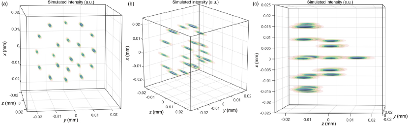
The subfigures show the same focus distribution for three different observation directions (a)–(c).
3.2 Material Processing Using Transverse and Longitudinal Beam Splitting
The efficacy of the diffractive 3D-beam splitting concept is demonstrated in the following by means of two selected examples. Usually, a measured focus distribution is used as proof for a successful beam shaping concept. In this work, on the other hand, we make use of the processing result and investigate the impact of the spatially and temporally shaped laser pulses on the material.
A first example is chosen to demonstrate the suitability of a multi-spot approach for efficient laser engraving of burr-free grooves in sheet steel with a processing speed of . Groove depth and width should exceed . Preliminary examinations on energy specific ablation volume have shown that for best efficiency was achieved for pulse durations of at fluences of .[10] Desired groove dimensions could be reached with multipath engraving of 81 passes at repetition rates of using a TruMicro 5070 laser system working in fundamental Gaussian-mode operation . In order to achieve the desired groove in a single pass, a diffractive optical element (DOE) was designed that yields Gaussian-like spots in a line of length using the employed --objective. The 2-inch DOE was realized as binary height profile etched in fused silica possessing an efficiency of , a uniformity error of and a relative zero-order power amount of merely . Figure 13
shows a corresponding ablation result with DOE aligned by intention perpendicular to the direction of feed to characterize the quality of the beam shaping concept. Each of the 81 engraved lines was generated by 81 passes (pulse duration , rep. rate , feed rate ) and exceed depths of proving the successful implementation of the beam shaping concept into the scanning system technology. This example clearly demonstrates the suitability of such a multi spot approach for processing along straight paths with high speed. The benefit from using split beams is not solely based on the increased processing speed. No detrimental effects due to heat accumulation are visible at an average power of about [10]. We want to emphasize at this point that the high processing speed becomes possible by the laser source and the beam splitting concept but are realized here by the dynamic of the scanning system. In general, large deflection angles () will result in field curvature aberrations (rotation of the focus line) and in coma/astigmatism aberrations of single spots (loss of peak intensity). Ideally, the design of the beam splitting DOE should take the imaging performance of the scanning objective into account.
By means of a second example we extend the beam splitting concept to the dimension of the beam propagation direction (-axis).
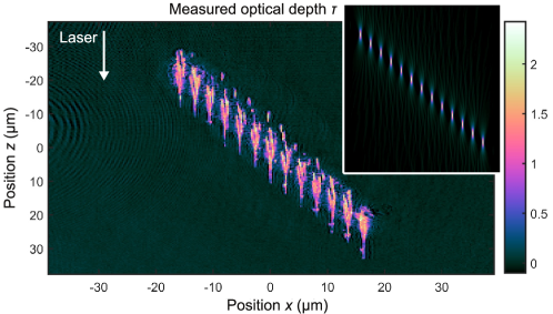
This enables higher flexibility for distributing the laser pulse energy within the working volume of the material to be processed (here: non-strengthened Corning Gorilla glass) and in particular to avoid shielding effects. Again, the spatial properties of the raw beam are assumed to be close to the diffraction limit (, fundamental Gaussian mode). An exemplary absorption distribution is shown in Fig. 14 [inset shows the computed spot profile, intensity representation, cf. Fig. 11 (c)] which was recorded using pump-probe microscopy (see Jenne et al.[40] for experimental details about the diagnostic tool). A single laser burst with pulses (pulse energy of ) emitted from a TruMicro 2000 with a pulse duration of was used. The measured optical depth (cf. Sec. 2.2) at a probe delay of indicates the optical losses due to, e.g., absorption or scattering on a transient temporal scale. For each of the 13 foci a single absorption zone is observed starting at the geometrical focus and expanding in direction of the incoming laser pulse. The behavior well known from focusing single Gaussian beams into transparent materials[41, 66] is multiplied here due to the beam splitting concept. Intriguingly, the spatial distribution of induced modification corresponds to the simulated focus positions and even at this small lateral and longitudinal spot separation of no shielding or inhomogeneities in between the individual spots is obtained. This denotes a precondition for advanced material processing in particular for scaling throughput in the field of cutting, material functionalization or welding.
4 Ultrafast drilling and structuring by digital holography
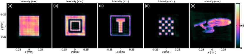
Ultrafast micron-scaled ablation, drilling or marking of solids have become well established industrial processes. Besides the availability of the required light source, one reason for this development can be found in the broad accessibility to multi-axis system technology in combination with advanced scanning systems, allowing arbitrary processing geometries. However, to maximize throughput beam shaping offers unmatched advantages over Gaussian processing. Especially ultrafast microprocesses benefit from large spatial intensity gradients combined with an extended single pulse processing volume. Efficient and flexible diffractive generation of such intensity distributions can be achieved by holographic methods [67, 68, 69, 70]. Figure 15 shows intensity measurements of exemplary shaped beams. Sharp edges close to the diffraction limit in combination with homogeneous intensity distributions can be applied for structuring or drilling with best quality and maximized throughput. The required micrometer-scaled dimensions are finally achieved using adapted telescopic setups.
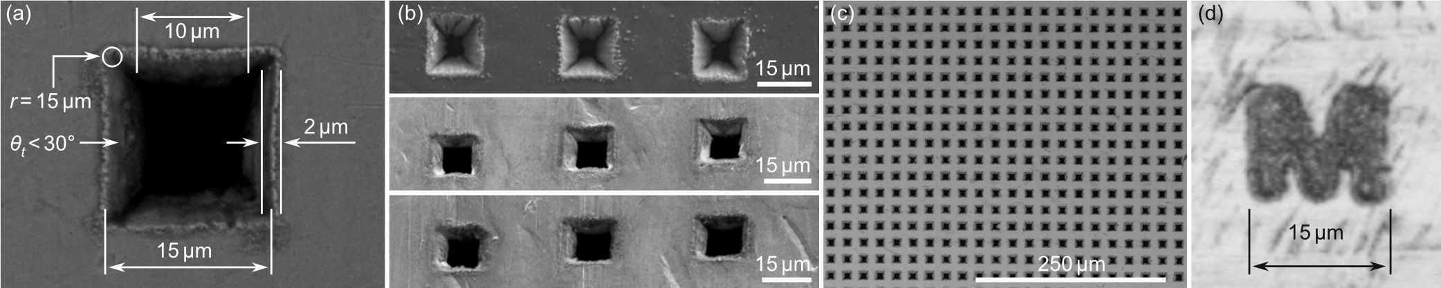
The in Fig. 15 (a) depicted flat top intensity profile at , generated by a spatial light modulator is demagnified using a -setup and applied in the following for the direct drilling of micro-shaped-holes. Such optimized drilling processes meet the demand for applications which require flexibility, best quality and high throughput. Such applications may be the drilling of high spatial frequency metal masks for spatially well confined evaporation of substrates for OLED display fabrication. These so-called Fine Metal Masks (FMMs) are subject to special requirements with regard to resolution, geometry and taper angle. For example, rectangular drilling holes with dimensions of about and resolutions are required. These level of freedom are easily achieved by means of holographic beam shaping concepts. In Fig. 16 we present as an example processing results of holes with a specifically designed taper angle of and an exit hole-diameter of achieved by percussion drilling using a TruMicro 2000 Series laser source.
5 Conclusion
Structured light concepts applied to ultrafast laser sources were presented and their potential for novel materials processing strategies were discussed. Digital-holographically generated Bessel-like beams with tailored trajectories in all spatial dimensions are used to precisely cut transparent materials with tailored edges. The implementation into industrial cleaving optics was demonstrated allowing single-pass full-thickness modification of glasses with thicknesses of up to . Additionally, we introduced concepts for arbitrarily splitting a large number of single spots into a three-dimensional working volume for exploiting the complete power performance of the laser source – a precondition for industrial material processing in particular for scaling throughput in the field of cutting, material functionalization or welding. Finally, we made use of digital holography for shaping quadratic micrometer-scaled flat-top-like beams with high-level of homogeneity and sharp edges for ultrafast drilling or structuring applications. This concept was used to generate high spatial frequency metal masks with holes densities of and controllable taper geometry.
The potential of structured light concepts was discussed for selected application examples. However, in principle, these concepts could not only be used for a plethora of ultrafast materials processing strategies but also for applications based on continuous-wave lasers, either working in spatial single- or multi-mode regime.
References
- [1] Q. Feng, J. V. Moloney, A. C. Newell, E. M. Wright, K. Cook, P. K. Kennedy, D. Hammer, B. Rockwell, and C. Thompson, “Theory and simulation on the threshold of water breakdown induced by focused ultrashort laser pulses,” IEEE journal of quantum electronics 33(2), pp. 127–137, 1997.
- [2] S. Nolte, C. Momma, H. Jacobs, A. Tünnermann, B. N. Chichkov, B. Wellegehausen, and H. Welling, “Ablation of metals by ultrashort laser pulses,” JOSA B 14(10), pp. 2716–2722, 1997.
- [3] A. Couairon and A. Mysyrowicz, “Femtosecond filamentation in transparent media,” Physics reports 441(2-4), pp. 47–189, 2007.
- [4] R. R. Gattass and E. Mazur, “Femtosecond laser micromachining in transparent materials,” Nature photonics 2(4), p. 219, 2008.
- [5] Y. Shimotsuma, P. G. Kazansky, J. Qiu, and K. Hirao, “Self-organized nanogratings in glass irradiated by ultrashort light pulses,” Physical review letters 91(24), p. 247405, 2003.
- [6] M. Kumkar, L. Bauer, S. Russ, M. Wendel, J. Kleiner, D. Grossmann, K. Bergner, and S. Nolte, “Comparison of different processes for separation of glass and crystals using ultrashort pulsed lasers,” in Frontiers in Ultrafast Optics: Biomedical, Scientific, and Industrial Applications XIV, 8972, p. 897214, International Society for Optics and Photonics, 2014.
- [7] A. Mathis, F. Courvoisier, L. Froehly, L. Furfaro, M. Jacquot, P.-A. Lacourt, and J. M. Dudley, “Micromachining along a curve: Femtosecond laser micromachining of curved profiles in diamond and silicon using accelerating beams,” Applied Physics Letters 101(7), p. 071110, 2012.
- [8] K. Bergner, M. Müller, R. Klas, J. Limpert, S. Nolte, and A. Tünnerman, “Scaling ultrashort laser pulse induced glass modifications for cleaving applications,” Applied optics 57(21), pp. 5941–5947, 2018.
- [9] M. Jenne, D. Flamm, T. Ouaj, J. Hellstern, J. Kleiner, D. Grossmann, M. Koschig, M. Kaiser, M. Kumkar, and S. Nolte, “High-quality tailored-edge cleaving using aberration-corrected bessel-like beams,” Optics letters 43(13), pp. 3164–3167, 2018.
- [10] M. Kumkar, M. Kaiser, J. Kleiner, D. Flamm, D. Grossmann, K. Bergner, F. Zimmermann, and S. Nolte, “Throughput scaling by spatial beam shaping and dynamic focusing,” in Laser Applications in Microelectronic and Optoelectronic Manufacturing (LAMOM) XXII, 10091, p. 100910G, International Society for Optics and Photonics, 2017.
- [11] K. Bergner, D. Flamm, M. Jenne, M. Kumkar, A. Tünnermann, and S. Nolte, “Time-resolved tomography of ultrafast laser-matter interaction,” Optics express 26(3), pp. 2873–2883, 2018.
- [12] AMPHOS: AMPHOS 400. https://www.amphos.de/products/amphos-400/. Accessed: 2019-01-07.
- [13] H. Rubinsztein-Dunlop, A. Forbes, M. V. Berry, M. R. Dennis, D. L. Andrews, M. Mansuripur, C. Denz, C. Alpmann, P. Banzer, T. Bauer, et al., “Roadmap on structured light,” Journal of Optics 19(1), p. 013001, 2016.
- [14] G. Zhu, J. Van Howe, M. Durst, W. Zipfel, and C. Xu, “Simultaneous spatial and temporal focusing of femtosecond pulses,” Optics express 13(6), pp. 2153–2159, 2005.
- [15] R. Kammel, R. Ackermann, J. Thomas, J. Götte, S. Skupin, A. Tünnermann, and S. Nolte, “Enhancing precision in fs-laser material processing by simultaneous spatial and temporal focusing,” Light: Science & Applications 3(5), p. e169, 2014.
- [16] J. Arlt, T. Hitomi, and K. Dholakia, “Atom guiding along laguerre-gaussian and bessel light beams,” Applied Physics B 71(4), pp. 549–554, 2000.
- [17] D. McGloin, V. Garcés-Chávez, and K. Dholakia, “Interfering bessel beams for optical micromanipulation,” Optics letters 28(8), pp. 657–659, 2003.
- [18] M. Bhuyan, F. Courvoisier, P. Lacourt, M. Jacquot, R. Salut, L. Furfaro, and J. Dudley, “High aspect ratio nanochannel machining using single shot femtosecond bessel beams,” Applied Physics Letters 97(8), p. 081102, 2010.
- [19] G. Zhang, R. Stoian, W. Zhao, and G. Cheng, “Femtosecond laser bessel beam welding of transparent to non-transparent materials with large focal-position tolerant zone,” Optics express 26(2), pp. 917–926, 2018.
- [20] J. Durnin, J. Miceli Jr, and J. Eberly, “Diffraction-free beams,” Physical review letters 58(15), p. 1499, 1987.
- [21] D. McGloin and K. Dholakia, “Bessel beams: diffraction in a new light,” Contemporary Physics 46(1), pp. 15–28, 2005.
- [22] D. Flamm, D. Grossmann, M. Kaiser, J. Kleiner, M. Kumkar, K. Bergner, and S. Nolte, “Tuning the energy deposition of ultrashort pulses inside transparent materials for laser cutting applications,” Proc. LiM 253, 2015.
- [23] J. Dudutis, R. Stonys, G. Račiukaitis, and P. Gečys, “Aberration-controlled bessel beam processing of glass,” Optics express 26(3), pp. 3627–3637, 2018.
- [24] J. Leach, G. M. Gibson, M. J. Padgett, E. Esposito, G. McConnell, A. J. Wright, and J. M. Girkin, “Generation of achromatic bessel beams using a compensated spatial light modulator,” Optics express 14(12), pp. 5581–5587, 2006.
- [25] asphericon: Asphericon Technologies. https://www.asphericon.com/en/technologies/. Accessed: 2018-11-20.
- [26] Powerphotonic: Rapid Prototyping. http://www.powerphotonic.com/rapid-prototyping. Accessed: 2018-11-26.
- [27] P. Boucher, J. Del Hoyo, C. Billet, O. Pinel, G. Labroille, and F. Courvoisier, “Generation of high conical angle bessel–gauss beams with reflective axicons,” Applied optics 57(23), pp. 6725–6728, 2018.
- [28] O. Brzobohatỳ, T. Čižmár, and P. Zemánek, “High quality quasi-bessel beam generated by round-tip axicon,” Optics express 16(17), pp. 12688–12700, 2008.
- [29] M. Kumkar, J. Kleiner, D. Großmann, D. Flamm, and M. Kaiser, “Optical system for beam shaping,” Sept. 14 2017. US Patent App. 15/598,816.
- [30] D. Flamm, K. Bergner, D. Grossmann, J. Hellstern, J. Kleiner, M. Jenne, S. Nolte, and M. Kumkar, “Higher-order bessel-like beams for optimized ultrafast processing of transparent materials,” in The European Conference on Lasers and Electro-Optics, p. CM_3_3, Optical Society of America, 2017.
- [31] R. Meyer, M. Jacquot, R. Giust, J. Safioui, L. Rapp, L. Furfaro, P.-A. Lacourt, J. Dudley, and F. Courvoisier, “Single-shot ultrafast laser processing of high-aspect-ratio nanochannels using elliptical bessel beams,” Optics letters 42(21), pp. 4307–4310, 2017.
- [32] T. Du, T. Wang, and F. Wu, “Generation of three-dimensional optical bottle beams via focused non-diffracting bessel beam using an axicon,” Optics Communications 317, pp. 24–28, 2014.
- [33] I. D. Chremmos, Z. Chen, D. N. Christodoulides, and N. K. Efremidis, “Bessel-like optical beams with arbitrary trajectories,” Optics letters 37(23), pp. 5003–5005, 2012.
- [34] D. A. Green, “A colour scheme for the display of astronomical intensity images,” arXiv preprint arXiv:1108.5083 , 2011.
- [35] M. Kumkar, J. Kleiner, D. Großmann, D. Flamm, and M. Kaiser, “System for asymmetric optical beam shaping,” Sept. 7 2017. US Patent App. 15/599,720.
- [36] M. Jenne, D. Flamm, D. Grossmann, J. Hellstern, T. Ouaj, M. Kumkar, and S. Nolte, “Glass cutting optimization with pump-probe microscopy and bessel beam profiles,” in Frontiers in Ultrafast Optics: Biomedical, Scientific, and Industrial Applications XVIII, 10522, p. 1052216, International Society for Optics and Photonics, 2018.
- [37] A. Dudley, M. Lavery, M. Padgett, and A. Forbes, “Unraveling bessel beams,” Optics and Photonics News 24(6), pp. 22–29, 2013.
- [38] A. Trichili, T. Mhlanga, Y. Ismail, F. S. Roux, M. McLaren, M. Zghal, and A. Forbes, “Detection of bessel beams with digital axicons,” Optics express 22(14), pp. 17553–17560, 2014.
- [39] C. Xie, V. Jukna, C. Milián, R. Giust, I. Ouadghiri-Idrissi, T. Itina, J. M. Dudley, A. Couairon, and F. Courvoisier, “Tubular filamentation for laser material processing,” Scientific reports 5, p. 8914, 2015.
- [40] M. Jenne, D. Flamm, M. Faber, D. Grossmann, J. Kleiner, F. Zimmermann, M. Kumkar, and S. Nolte, “Pump-probe microscopy of tailored ultrashort laser pulses for glass separation processes,” in Laser-based Micro- and Nanoprocessing XIII (to be published), International Society for Optics and Photonics, 2019.
- [41] D. Grossmann, M. Reininghaus, C. Kalupka, M. Kumkar, and R. Poprawe, “Transverse pump-probe microscopy of moving breakdown, filamentation and self-organized absorption in alkali aluminosilicate glass using ultrashort pulse laser,” Optics express 24(20), pp. 23221–23231, 2016.
- [42] K. Itoh, W. Watanabe, S. Nolte, and C. B. Schaffer, “Ultrafast processes for bulk modification of transparent materials,” MRS bulletin 31(8), pp. 620–625, 2006.
- [43] B. Rethfeld, K. Sokolowski-Tinten, D. Von Der Linde, and S. Anisimov, “Timescales in the response of materials to femtosecond laser excitation,” Applied Physics A 79(4-6), pp. 767–769, 2004.
- [44] F. Wyrowski and C. Hellmann, “Geometrical optics reloaded: Physical optics modeling with smart rays,” Optik & Photonik 10(5), pp. 43–47, 2015.
- [45] R. J. Noll, “Zernike polynomials and atmospheric turbulence,” J. Opt. Soc. Am. 66, pp. 207–211, Mar 1976.
- [46] C. Schulze, A. Dudley, D. Flamm, M. Duparré, and A. Forbes, “Reconstruction of laser beam wavefronts based on mode analysis,” Applied optics 52(21), pp. 5312–5317, 2013.
- [47] TRUMPF: TOP Cleave cutting optics. https://www.trumpf.com/en_US/products/lasers/processing-optics/top-cleave-cutting-optics/. Accessed: 2018-11-28.
- [48] F. Jansen, A. Budnicki, and D. Sutter, “Pulsed lasers for industrial applications: Fiber, slab and thin-disk: Ultrafast laser technology for every application,” Laser Technik Journal 15(2), pp. 46–49, 2018.
- [49] M. Kumkar, D. Großmann, and D. Flamm, “Diffractive optical beam shaping element,” Sept. 28 2017. US Patent App. 15/599,623.
- [50] T. Eidam, S. Hanf, E. Seise, T. V. Andersen, T. Gabler, C. Wirth, T. Schreiber, J. Limpert, and A. Tünnermann, “Femtosecond fiber CPA system emitting 830 W average output power,” Optics letters 35(2), pp. 94–96, 2010.
- [51] H. Fattahi, H. G. Barros, M. Gorjan, T. Nubbemeyer, B. Alsaif, C. Y. Teisset, M. Schultze, S. Prinz, M. Haefner, M. Ueffing, et al., “Third-generation femtosecond technology,” Optica 1(1), pp. 45–63, 2014.
- [52] J.-P. Negel, A. Loescher, A. Voss, D. Bauer, D. Sutter, A. Killi, M. A. Ahmed, and T. Graf, “Ultrafast thin-disk multipass laser amplifier delivering 1.4 kW (4.7 mJ, 1030 nm) average power converted to 820 W at 515 nm and 234 W at 343 nm,” Optics express 23(16), pp. 21064–21077, 2015.
- [53] N. Streibl, “Beam shaping with optical array generators,” Journal of Modern Optics 36(12), pp. 1559–1573, 1989.
- [54] H. Ren, H. Lin, X. Li, and M. Gu, “Three-dimensional parallel recording with a debye diffraction-limited and aberration-free volumetric multifocal array,” Optics letters 39(6), pp. 1621–1624, 2014.
- [55] L. Zhu, M. Sun, M. Zhu, J. Chen, X. Gao, W. Ma, and D. Zhang, “Three-dimensional shape-controllable focal spot array created by focusing vortex beams modulated by multi-value pure-phase grating,” Optics express 22(18), pp. 21354–21367, 2014.
- [56] M. Gu, X. Li, and Y. Cao, “Optical storage arrays: a perspective for future big data storage,” Light: Science & Applications 3(5), p. e177, 2014.
- [57] A. Jesacher and M. J. Booth, “Parallel direct laser writing in three dimensions with spatially dependent aberration correction,” Optics express 18(20), pp. 21090–21099, 2010.
- [58] R. D. Simmonds, P. S. Salter, A. Jesacher, and M. J. Booth, “Three dimensional laser microfabrication in diamond using a dual adaptive optics system,” Optics express 19(24), pp. 24122–24128, 2011.
- [59] D. Flamm, D. Naidoo, C. Schulze, A. Forbes, and M. Duparré, “Mode analysis with a spatial light modulator as a correlation filter,” Optics letters 37(13), pp. 2478–2480, 2012.
- [60] A. Forbes, A. Dudley, and M. McLaren, “Creation and detection of optical modes with spatial light modulators,” Advances in Optics and Photonics 8(2), pp. 200–227, 2016.
- [61] J. A. Davis, D. M. Cottrell, J. Campos, M. J. Yzuel, and I. Moreno, “Encoding amplitude information onto phase-only filters,” Applied optics 38(23), pp. 5004–5013, 1999.
- [62] V. Arrizón, U. Ruiz, R. Carrada, and L. A. González, “Pixelated phase computer holograms for the accurate encoding of scalar complex fields,” JOSA A 24(11), pp. 3500–3507, 2007.
- [63] M. Leutenegger, R. Rao, R. A. Leitgeb, and T. Lasser, “Fast focus field calculations,” Optics express 14(23), pp. 11277–11291, 2006.
- [64] F. Wyrowski and O. Bryngdahl, “Iterative fourier-transform algorithm applied to computer holography,” JOSA A 5(7), pp. 1058–1065, 1988.
- [65] M. Jenne, F. Zimmermann, D. Flamm, D. Großmann, J. Kleiner, M. Kumkar, and S. Nolte, “Multi pulse pump-probe diagnostics for development of advanced transparent materials processing,” JLMN 13(3), pp. 273–279, 2018.
- [66] K. Bergner, B. Seyfarth, K. Lammers, T. Ullsperger, S. Döring, M. Heinrich, M. Kumkar, D. Flamm, A. Tünnermann, and S. Nolte, “Spatio-temporal analysis of glass volume processing using ultrashort laser pulses,” Applied optics 57(16), pp. 4618–4632, 2018.
- [67] F. M. Dickey and S. C. Holswade, “Laser beam shaping: Theory and techniques,” 2000.
- [68] V. Pal, C. Tradonsky, R. Chriki, N. Kaplan, A. Brodsky, M. Attia, N. Davidson, and A. A. Friesem, “Generating flat-top beams with extended depth of focus,” Applied optics 57(16), pp. 4583–4589, 2018.
- [69] A. Hendriks, D. Naidoo, F. S. Roux, C. López-Mariscal, and A. Forbes, “The generation of flat-top beams by complex amplitude modulation with a phase-only spatial light modulator,” in Laser Beam Shaping XIII, 8490, p. 849006, International Society for Optics and Photonics, 2012.
- [70] D. Naidoo, I. A. Litvin, and A. Forbes, “Brightness enhancement in a solid-state laser by mode transformation,” Optica 5(7), pp. 836–843, 2018.