Current address: Helmholtz Institute Münster (IEK-12), Ionics in Energy Storage, Forschungszentrum Jülich GmbH, Corrensstraße 46, 48149 Münster, Germany
Understanding the Lithium Ion Transport in Concentrated Block–Copolymer Electrolytes on a Microscopic Level
Abstract
Block–copolymer electrolytes with lamellar microstructure show promising results regarding the ion transport in experiments. Motivated by these observations we study block–copolymers consisting of a polystyrene (PS) block and a poly(ethylene oxide) (PEO) block which were assembled in a lamellar structure. The lamella was doped with various amounts of lithium-bis(trifluoromethane)sulfonimide (LiTFSI) until very high loadings with ratios of EO monomers to cations up to 1:1 were reached. We present insights into the structure and ion transport from extensive Molecular Dynamics simulations. For high salt concentrations most cations are not coordinated by PEO but rather by TFSI and THF. More specifically, LiTFSI partially separates from the PEO domain and forms a network–like structure in the middle of the lamella. This central salt–rich layer plays a decisive role to enable remarkably good cationic mobilities as well as high transport numbers in agreement with the experimental results.
1 Introduction
Solid polymer electrolytes (SPEs) are extensively investigated because of their potential to unlock novel battery chemistry. 1, 2, 3, 4 Replacing the commonly used graphite anode material with lithium metal gives rise to batteries with higher capacities and higher specific energies. 5, 4, 6 Such secondary lithium metal batteries suffer from electrolyte depletion due to parasitic side reactions and possibly fatal thermal runaway due to dendrite growth. 7, 8, 9, 10 Electrolytes consisting of flammable organic liquids do not prevent parasitic side reactions and dendrite formation but offer good ionic conductivities. 11, 12, 13 SPEs are less volatile and therefore increase cell safety.
Poly(ethylene oxide) (PEO) has been identified as a suitable candidate for SPEs. 14, 15, 16, 17 Unfortunately PEO exhibits poor ionic conductivity at ambient temperature caused by crystallization. The conductivity of PEO has a low cationic contribution because the polymer chains strongly coordinate the cations. 15, 16, 18 It has been shown that the conductivity can be improved by increasing the segmental motion of the polymer chains. 19, 18, 20 Therefore, shorter PEO chains are favored because they have a higher mobility and tend to crystallize less. On the other hand Monroe and Newman 21, 22, 23 have shown that a high shear modulus is essential in order to prevent dendrite formation. The necessary rigidity is hardly reachable even with long PEO chains and hinders the ion transport.24, 25, 26 A proposed solution to the conflicting mechanical and electrical properties are block copolymers (BCPs) which are able to decouple both properties as follows: BCPs consist of chemically dissimilar polymer blocks that are covalently bonded end–to–end so that each block can be optimized for a specific property. Typically, nonconductive blocks are used to tune mechanical properties and PEO is used to form conducting pathways. 27, 28, 29, 30, 25 Depending on the properties of the individual blocks BCPs give rise to microphase separation and the conductivity consequently depends on the formed microstructure. 26, 31, 25 Contrary to PEO homopolymers the conductivity of such BCPs increases with longer PEO chains for intermediate chain lengths.29, 26, 32
Recently Dörr et al. 33 and Pelz et al. 34 have studied block copolymers with unusually short PEO chains () that allow high lithium salt loadings of \ceLiTFSI. In the experiments a ratio of 4.3 \ceLi+ per ethylene oxide monomer (EO) has been identified as optimum in the conductivity. Those BCPs self–assemble into lamellar microstructures that exhibit a remarkably good total conductivity of at with a weak temperature dependence and a high lithium ion transference number of 0.7.34 The preparation was done by evaporation–induced self–assembly using tetrahydrofuran (\ceTHF) as solvent. \ceTHF could not be evaporated completely from these samples, consequently it was postulated that \ceTHF takes an important role in the coordination of \ceLi+.33 It was found that thermal annealing increases the conductivity presumably by a long–range ordering of the lamellar structures.33 Utilizing small–angle X–ray scattering (SAXS) it has been observed that the addition of salt selectively swells the PEO domain which results in an increase of the overall bilayer thickness from in neat polymer to in the best conducting sample.33 This pronounced swelling can be an indication of the formation of a salt–rich phase in the PEO domain. Remarkably wide–angle X–ray scattering (WAXS) reveals a strongly crystalline phase that did not vanish even at a high temperature of .34
In this contribution we focus on the \ceLi+ coordination in this high performance electrolyte and provide insights into the structure and dynamics of the reported lamellae by means of molecular dynamics (MD) simulations. Specifically the formation of a salt–rich central layer is addressed and we clarify that this layer is the origin of the desirable electrochemical properties. We can consequently rationalize the experimentally observed salt–rich phase, the high cationic transference number, and the swelling of the PEO domain. The next section presents details of the simulation method, followed by a discussion of our results. In the end we give a brief summary of our findings.
2 Simulation Details
Version 2019 of the molecular dynamics simulation package GROMACS 35 was used to perform all simulations within a three–dimensional periodic cubic simulation box. Each simulation box contains a certain number of polymer chains, \ceLiTFSI ion pairs and \ceTHF. An overview of the composition of the simulated systems is given in Table 1.
| 20:1:0 | 50 | 120 | — |
| 20:2:1 | 50 | 240 | 120 |
| 10:2:1 | 50 | 480 | 240 |
| 4:2:1 | 50 | 1200 | 600 |
| 3:2:1 | 50 | 1600 | 800 |
| 2:2:1 | 50 | 2400 | 1200 |
| 5:5:3 | 50 | 2400 | 1440 |
| 4:4:3 | 50 | 2400 | 1800 |
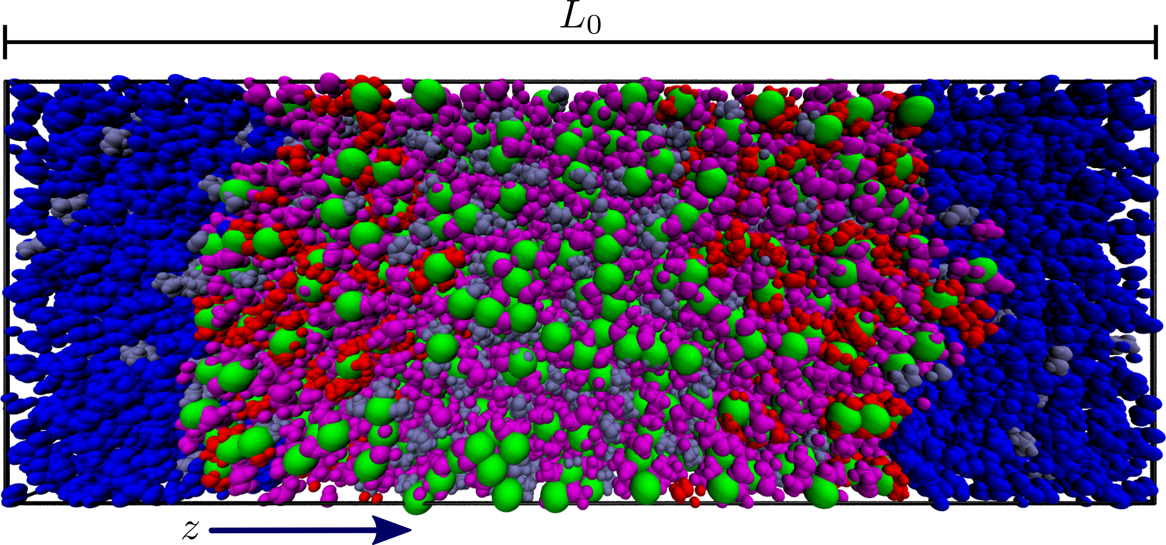
The systems are named from here on according to their ratio of EO to cations to \ceTHF. Although experimentally systems with a ratio of EO to \ceLi+ of up to 1:5 have been investigated in references 33, 34 the following simulations only consider ratios of up to 1:1. This was done to decrease the computational cost and because higher salt concentrations would only provide limited additional insights into the electrolyte structure. As discussed later, it can be expected that additional salt only thickens the salt layer in the middle rather than interacting with the block copolymer. Generally the number of \ceTHF molecules is chosen to be half the number of ion pairs (see discussion in SI). It should be noted that the 20:1:0 system does not contain any \ceTHF and serves as a reference system with a typical lithium concentration. Other exceptions are the 5:5:3 and 4:4:3 systems that contain and more \ceTHF as compared to the 2:2:1 system. This is due to the large uncertainty in the experimental measurements of the \ceTHF content and to test the influence of \ceTHF in those salt–rich systems. The 2:2:1, 5:5:3, and 4:4:3 systems have a ratio of EO to cations of 1:1 and are therefore collectively referred to as :: systems. All but the :: systems have been prepared the following way (cf. Figure 1 and LABEL:fig:si_snapshot in SI): The polymers are copolymers consisting of a PS block with 48 monomers and a PEO block with likewise 48 monomers. Those polymers have the same number of EO monomers as in the experiments done by Dörr et al. 33 and Pelz et al.34 In order to reduce the computational cost the length of the PS block is shorter than in these experiments. Furthermore, there is no third polyisoprene block like in the experimental samples. However, these changes are inconsequential for the structure of the ion conductive domain, as these blocks are apolar and hence are not expected to interact with the salt (see also below). PACKMOL 36 was used to generate the starting configurations. The block copolymers are initially arranged in a bilayer so that the same blocks of the bottom and top layer point towards each other and form a PEO domain and a PS domain. There is one bilayer within the simulation box and \ceTHF is randomly placed across the whole box. The ion pairs are randomly positioned within the PEO domain because it has been shown that ions preferentially reside in this polar oxygen–rich domain. 37, 38 The :: systems were prepared based on the structure of the 4:2:1 system after equilibration. Additional \ceLiTFSI and \ceTHF was inserted in the middle of the PEO domain and the equilibration routine was repeated. This preparation procedure is justified by computational and experimental arguments in Section 3.1. Simulations were performed using a NpT ensemble controlled by a Nosé–Hoover thermostat 39, 40 and Parrinello–Rahman barostat.41 The barostat acts semiisotropically with a coupling pressure of . A equilibration run was performed with after the initial simulation box was shrunken to a reasonable size. Subsequently, the temperature was reduced to and the systems were equilibrated for at least . Afterwards a production run of was performed for all systems but the 3:2:1 system, which was only used to study the partial separation of salt from the polymer domain (see below). Simulations were propagated with a time step of and a cutoff of for Van der Waals interactions. The Coulomb interactions were treated with the particle mesh Ewald (PME) method.42, 43 A cutoff distance of , a grid spacing of , and an interpolation order of 6 are used as PME settings.
To describe the particle interactions the OPLS 44 force field was used. The \ceLi+ particles are described by parameters from reference 45 and the parameters of PEO and \ceTHF are chosen according to reference 46. The force field parameters of PS are based on references 47, 48. TFSI anions are parameterized as described in reference 49. The OPLS force field does not account for polarization effects. To approximate polarization a factor of 0.8 is used to scale partial charges of both ion species. Several other studies have shown that this leads to better agreement with experiments.50, 51, 52
3 Results and Discussion
3.1 Composition Across the Bilayer
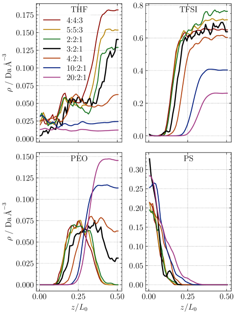
First the distribution of the different components is analyzed with respect to the bilayer normal (see Figure 1). In the following the distribution of the mass density of a certain component is calculated along the normalized bilayer height . Absolute values for the bilayer height are tabulated in SI LABEL:tab:box_dims. Because of the symmetry of the bilayer, the density in the interval is mirrored in the interval . For this reason the mass density is averaged over both intervals and subsequent depictions show solely the interval . An overview over the densities of all residues is given in Figure 2.
During the extensive equilibration and production run the \ceLiTFSI salt exclusively stays within the PEO domain. This matches the assumed behavior during construction of the initial configuration in Section 2. Other simulation studies have observed a small population of ions which reside within the nonconductive PS phase, which exhibit stronger anion–cation coordination and lower mobilities, when using \ceLiPF6 as salt and a different force field.53, 54, 55 Apparently, \ceLiTFSI has a lower tendency to form small neutral clusters that can migrate into the apolar PS domain because this salt dissociates more easily.
The distribution of the mass density of PEO in the 4:2:1 system decreases towards the middle of the bilayer at (note that this also allowed for the insertion of additional salt to create the :: systems, see Section 2). The decrease of PEO towards the middle of the bilayer is even more pronounced in the 3:2:1 system, which was deliberately set up to study the formation of the salt–rich layer. Figure 3 allows for a visual inspection of the polymer chains in this system which clearly shows a separation of the bilayer in the middle during equilibration.
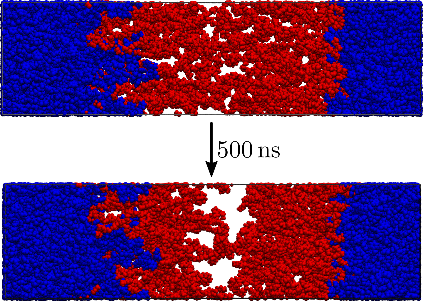
This emerging gap is occupied by a mixture of \ceTHF and \ceLiTFSI. As indicated by this observation, it is reasonable to assume that a salt layer is formed in highly concentrated systems. However, even after an equilibration run of the 3:2:1 system is not fully equilibrated. In this system the salt gradually leaves the PEO domain which causes an increase of PEO in that region (see LABEL:fig:si_peo_profile_ts and LABEL:fig:si_peo_p_ts). This suggests a rather slow assembly of the salt layer and justifies our strategy to insert this layer directly in the :: systems which yields equilibrated structures at a significantly reduced computational cost, as in the :: systems the salt layer remains present over the whole simulation time. Analysis of the diffusion coefficients within this salt layer in Section 3.5 shows that all electrolyte components exhibit displacements during the production run that are sufficiently large to allow exchange between the salt layer and the PEO domain. As discussed in Section 2, this salt layer has also been observed experimentally, which also motivated our study.33, 34
Of particular interest is the distribution of \ceTHF because of its postulated important role in the coordination of \ceLi+ in reference 33. The mass density of \ceTHF along the normalized bilayer height is shown in Figure 2 (upper left). The 20:2:1 system exhibits an approximately homogeneous distribution of \ceTHF across the PS and PEO block. \ceTHF acts in this case as a non–selective solvent that has no preference for one block over the other. In the 10:2:1 system \ceTHF is most concentrated between the adjacent PS domains of the top and bottom layer around . For higher salt concentrations however \ceTHF prefers residence in the polar salt–rich region due to favorable interactions with \ceLiTFSI. Interestingly there is a locally higher density of \ceTHF at the interface between PS and PEO blocks of the block copolymers. This effect has been attributed to a decrease in contacts between the immiscible PS and PEO blocks caused by the solvent.56, 57 An orientation in which the \ceTHF oxygens point towards the PEO domain is favored at this interface (not shown). The shift of this locally higher density of \ceTHF between the 4:2:1 and 2:2:1 systems hints at a swelling of the PEO domain due to the additional salt. Motivated by the observation that \ceTHF preferentially resides in the salt rich domain the coordination environment of \ceLi+ is further characterized in the following sections.
3.2 Coordination Numbers
Radial distribution functions (RDFs) are used to identify atoms that coordinate cations. The examination of the RDFs of different oxygen types, belonging to anions, PEO, and THF shows a distinct inner peak for all three residues that is caused by the first coordination shell (see SI LABEL:fig:si_rdf_tfsi and LABEL:fig:si_rdf_ether). The shape of the RDFs has been extensively discussed in the past.58, 59, 60, 61 This first coordination shell is fully contained within a distance of from the cation. Based on this observation all oxygen atoms with a distance can be defined as coordinating a cation.
By counting the number of oxygen atoms within the first coordination shell of the cations the coordination number can be determined. The average coordination number for oxygen atoms of the various residues in the simulated systems is shown in Figure 4.
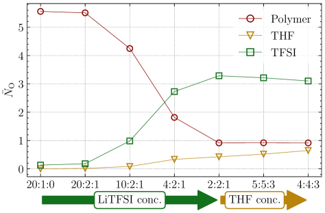
In systems with a \ceLiTFSI concentration of 10:2:1 and lower, the average coordination number of polymer oxygen is around five and thus matches other reported values. 62, 63, 59 Generally the number of coordinating polymer oxygens decreases with increasing salt concentration for all simulated systems. The largest reduction of for the polymer occurs when increasing the salt concentration from 10:2:1 to 4:2:1. The resulting coordination number in the 4:2:1 system is just below two. It can be argued that the 10:2:1 system provides just enough oxygen atoms from the polymer so that the PEO chains can wrap around the cations. For higher salt concentrations the PEO chains might unwrap and stretch to accommodate more cations on the chain which explains the lower number of coordinating polymer oxygens in the 4:2:1 system. In the 4:2:1 system the polymer chains are saturated with cations and consequently the number of cations per polymer chain cannot increase further when adding salt (see SI LABEL:fig:si_coord_res_li (left)). The proposed unwrapping of the PEO chains allows for other ligands to coordinate cations too which leads to mixed coordination environments as discussed next.
Contrasting with the coordination number of polymer oxygens, the number of coordinating \ceTFSI oxygens generally increases for higher salt concentrations. In systems with a salt concentration of 10:2:1 and lower, for \ceTFSI is below one. In the 4:2:1 and :: systems, for the anions is around three. Therefore, the largest increase of the number of coordinating \ceTFSI oxygen atoms can be observed between the 10:2:1 and 4:2:1 systems. Again this can be explained by the saturation of the polymer chain with coordinating cations. PEO oxygens are preferred for coordinating cations but, if there are not enough free polymer oxygens available, \ceTFSI coordinates instead. Between two and three coordinating cations per anion can be observed in the 4:2:1 and :: systems (cf. SI LABEL:fig:si_coord_res_li (left)). A single \ceTFSI molecule is typically able to coordinate a \ceLi+ with either one (monodentate) or two oxygen atoms (bidentate). LABEL:fig:si_coord_res_li (right) in SI shows that the majority of cations is only coordinated by monodentate \ceTFSI in the 10:2:1 system and systems with less salt. This fraction steeply increases with the addition of salt between the 20:2:1 and 10:2:1 systems and reaches a plateau of for all higher salt concentrations. The previously observed increase of the coordinating \ceTFSI oxygen atoms between the 10:2:1 and 4:2:1 systems can be attributed to an increase of bidentate \ceTFSI. In the 4:2:1 and :: systems the majority of cations is coordinated by at least one bidentate \ceTFSI.
The average coordination number of \ceTHF is below one in all systems and it is the smallest of all three ligand residues. For the systems with a salt concentration of 10:2:1 and lower, virtually no coordination of the cations by \ceTHF can be found. In the 4:2:1 and :: systems for \ceTHF increases slightly which again can be explained by the saturation of the polymer chain with cations. Similar to the anions \ceTHF substitutes the missing PEO oxygen in the cation coordination. This substitution however is not as pronounced as for the \ceTFSI. When the \ceTHF concentration is increased in the :: systems for \ceTHF increases as well, while for the \ceTFSI coordination decreases slightly. In those systems \ceTHF seems to be able to replace some coordinating anion oxygens. The coordination number of polymer oxygens does not change upon increased \ceTHF content.
3.3 Number of Coordinating Residues
Next we investigate the \ceLi+ coordination in more detail by analyzing the number of coordinating residues. A residue is counted as coordinating if at least one of its oxygen atoms resides within the first coordination shell of a given cation. In Figure 5 the fraction of cations with a certain number of coordinating residues is shown.
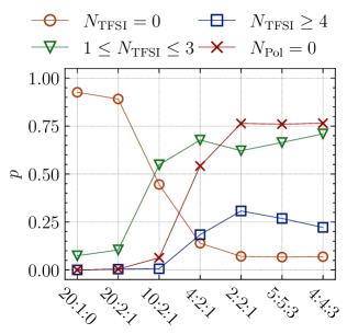
Systems with a salt concentration of 10:2:1 and lower have nearly all of their cations coordinated by the polymer which is indicated by a low fraction of . Moreover, in systems with a salt concentration of 20:2:1 and lower, most cations are exclusively coordinated by polymer, reflected by a high fraction of . Increasing the \ceLiTFSI concentration from 10:2:1 to 4:2:1 results in a sharp rise of the fraction of cations with . In the 4:2:1 system less than half of all cations are coordinated by PEO chains. The fraction of cations that are not coordinated by polymer further rises to around in the :: systems. As before, the addition of \ceTHF in those systems does not change the polymer coordination. Further investigations reveal that cations coordinated by the polymer have typically only one attached PEO chain. Only in the 20:1:0 and 20:2:1 systems cations with two coordinating PEO chains are found in low numbers (). The low occurrence of such coordination environments has already been discussed in reference 64.
The inverse behavior between the fraction of cations that have no anion coordination () and cations without polymer coordination () is as expected. The fraction of cations with generally declines for higher salt concentrations. In the 20:1:0 and 20:2:1 systems most cations do not have coordinating anions, whereas more than half of all cations are coordinated by one to three \ceTFSI in the 10:2:1 system. Higher coordination numbers are not observed in this system. In the 4:2:1 system most of the cations are coordinated by up to three anions. The fraction of cations with further decreases to approximately . Notably roughly the same number of cations have four or more coordinating \ceTFSI (). By increasing the salt concentration to 2:2:1 the fraction of cations with increases while the fraction of cations without \ceTFSI decreases. These high coordination numbers are especially prevalent in the salt–rich layer in the middle of the bilayer as discussed later on. The fraction of cations that have one to three neighboring anions declines slightly due to the overall higher number of \ceLi+ and the pronounced central salt–rich layer.
The previous observations seem to suggest the formation of a network–like structure constructed from anions that are linked by cations in systems with a salt concentration of 4:2:1 and above. This is because anions coordinate to multiple cations and vice versa. The proposed network–like structure is characterized in detail by determining the sizes of clusters formed by anion–cation aggregates (cf. SI LABEL:fig:si_clusters). The cluster size is defined as the number of cations interconnected by bridging anions. Cations bridged by PEO chains are not considered to be in the same cluster. In the 20:1:0 and 20:2:1 systems virtually no anion–cation aggregates are formed matching the observed low coordination numbers of \ceTFSI around \ceLi+. In the 10:2:1 system approximately of the cations are part of small clusters consisting of less than 10 cations. Contrary to the low salt systems most cations are part of a single large network in the 4:2:1 and :: systems. In the 4:2:1 system just slightly more than half of all cations are part of this network. But in the :: systems more than of cations are interconnected by \ceTFSI. Comparable observations have also been made in concentrated mixtures with other salts and solvents, and it has been proposed that such structures favor a hopping based transport mechanism.65, 66 Figure 6 shows common structural motifs found in this network.
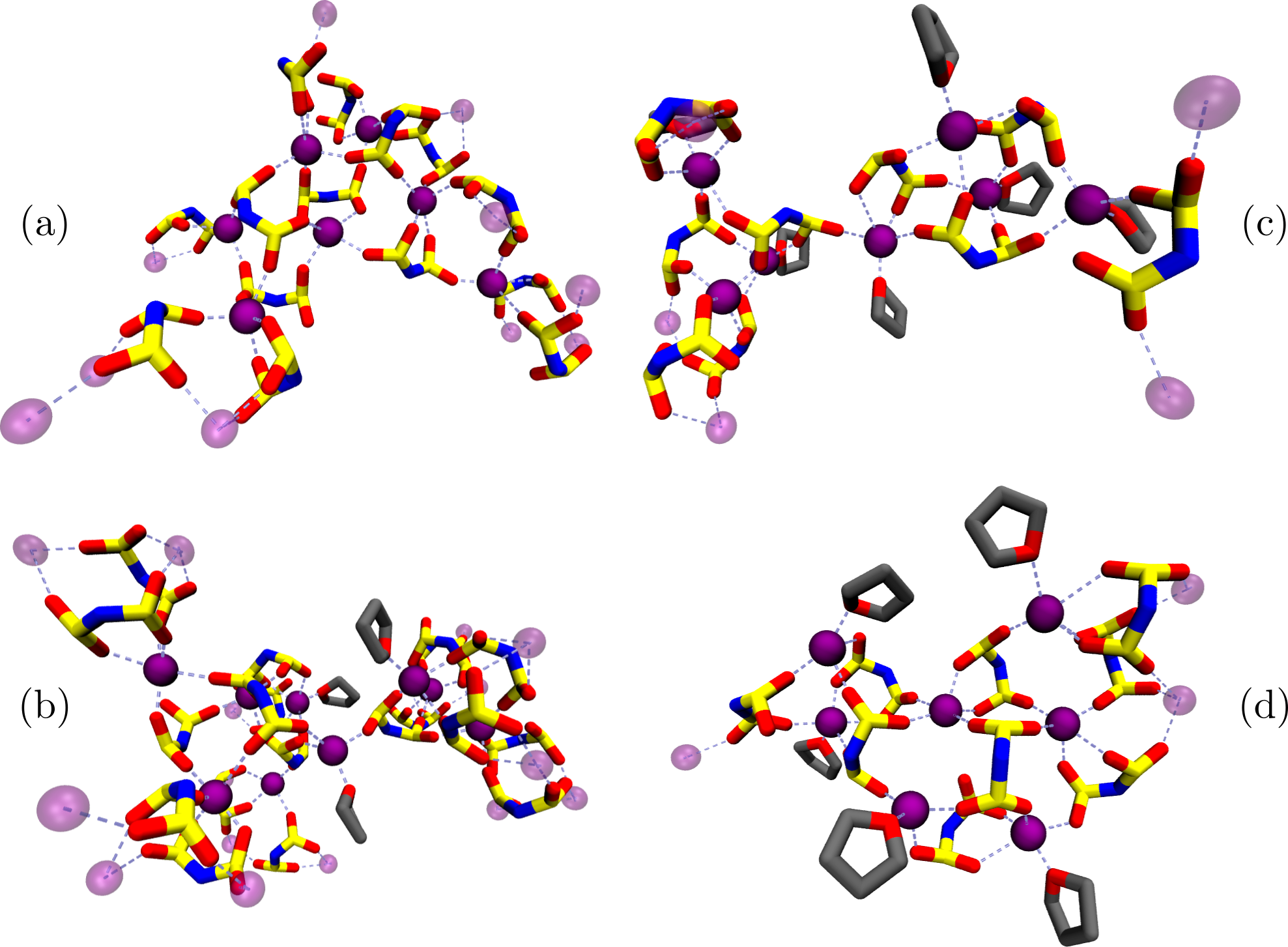
Additional \ceTHF in those systems detaches \ceTFSI from highly coordinated cations and is therefore able to partially break up the network–like structure as indicated by a reduction of in Figure 5. This results in a reduced fraction of cations contained within the network (cf. SI LABEL:fig:si_clusters). The partial break up of the network is also visually supported by the observation that \ceTHF seems to be able to separate highly interconnected regions (cf. Figure 6).
To understand why the polymer coordination drops steeply between the 10:2:1 and 4:2:1 systems the coordination number is spatially resolved across the bilayer (cf. SI LABEL:fig:si_coord_profile). For systems with a salt concentration of 10:2:1 and lower the coordination of PEO, \ceTFSI and \ceTHF is homogeneous across the PEO domain. This holds true for the number of coordinating atoms as well as residues (not shown). The 4:2:1 system exhibits two differences when compared to systems with lower salt concentrations: First there is a significant amount of cations between the PEO chains that are not directly attached to those chains (see at and ). They are coordinated by anions and \ceTHF only and constitute approximately of the cations that reside within the PEO domain (note that the overall fraction of cations without neighboring PEO in Figure 5 is higher because of the additional cations in the salt layer). Consequently, the PEO chains have to be further apart to accommodate the salt. This is also reflected by the values in LABEL:tab:box_dims which increase with higher salt concentrations. Second the distance between the top and bottom layer of the block copolymer bilayer increases which causes diminished coordination by PEO in the middle of the bilayer. Presumably the salt cannot be fully accommodated by lateral swelling of the PEO domain and a salt–rich layer in the middle of the bilayer is formed. As discussed in context of Figures 2 and 3, the swelling increases further in the :: systems so that the PEO domain becomes completely separated by a layer in the middle where no polymer coordination of \ceLi+ is observed. This assumption is in accordance with the experimental SAXS data in references 33, 34. In this layer the cations are coordinated predominantly by \ceTFSI but upon adding \ceTHF in the :: systems this additive increasingly takes part in the coordination as well.
3.4 Polymer Structure
As a first assessment of the structure of the block copolymers the radius of gyration is calculated for the PS and PEO block independently. The resulting values of are shown in Figure 7 (top).
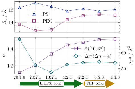
The radius of gyration for the PS chains generally decreases if the \ceLiTFSI concentration is increased. This is not the case for the 20:1:0 system because in this system is lower than in the next higher concentrated system. Presumably this might be related to the fact that the 20:1:0 system does not contain any \ceTHF. Therefore, one can reasonably assume that \ceTHF as a solvent within the PS block allows stretching of the PS chains in the 20:2:1 system.67 The previously discussed mass density within the bilayer (cf. Figure 2) shows however that with an increased number of \ceTHF molecules the density of \ceTHF within the PS block expectedly increases as well. At first glance this contradicts the observed decrease in the radius of gyration for higher \ceLiTFSI concentrations because it is expected that \ceTHF stretches the chains. As discussed in the previous section, the lateral size of the simulation box increases upon adding salt. Consequently, the PS chains have to be further apart so that a more compact conformation is adopted to fill the created interstice which results in a smaller . Complementary one can argue that the increasing amount of salt within the PEO block immobilizes the block copolymers and prompts a clearly defined phase separation between apolar PS chains and PEO embedded in salt.37 Analysis of the mean squared displacement (MSD) of both the EO and PS monomers display decreasing mobility for systems with more salt (not shown). Additionally, the ability of salt to promote demixing is also reported in references 68, 69, 70, 71. Both effects may lead to compression of the PS block and for the PS chains decreases. This compression effect seems to be limited because the observed change between the 4:2:1 and :: systems is negligible. The systems with a salt concentration of :: exhibit no pronounced influence of additional \ceTHF because the added solvent predominantly resides within the polar salt layer.
The radius of gyration for the PEO chains is minimal for a salt concentration of 20:2:1 and 10:2:1. The PEO chains exhibit the least amount of stretching in those systems because most cations are coordinated by PEO in such a way that the PEO chains are wrapped around the cations. Fewer cations that cause wrapping of the PEO chains result therefore in a higher in the 20:1:0 system. Salt concentrations of 4:2:1 and higher result in a higher as well because the PEO chains are saturated with cations and have to stretch to accommodate additional cations. Similar behavior is also captured by the end–to–end distance of the PEO chains which complements (cf. SI LABEL:fig:si_ree).
To investigate the stretching of the PEO chains further the squared distance between two EO monomers of the same chain can be described as a function of the number of interjacent monomer–monomer bonds. It is expected that this distance generally follows the form . The parameter can be called stretching parameter. In case of a fully elongated chain the stretching parameter has a value of . It can be shown that if the chain describes a random walk the stretching parameter has a value of .72 Since the block copolymers assemble in a bilayer, the PEO chains are not fully free to move. They are fixed in place by cohesion of the PS blocks. Milner 67 proposes a model which describes the elongation of polymer chains that form such a brush–like structure. This approach describes fully elongated chains () in the presence of an ideal solvent and less stretched chains with without a solvent.
It is possible to compute a local estimate for the stretching parameter of a segment with length as numerical derivative of :
| (1) |
Numerical analysis of (1) reveals three distinct aspects for segments of length (cf. SI LABEL:fig:si_alpha_local): Short segments exhibit a minimum of at . A plateau of is reached for medium–sized segments in the interval . For long segments the approximation of the stretching parameter is influenced by finite–size effects at the ends of the chains. Those effects arise from the entropic repulsion of distinct segments due to excluded volume effects, which is less pronounced for the chain ends.73 As argued in the previous sections the PEO chains wrap around cations with up to five continuous oxygen atoms, i.e. segments of lengths . Since this exactly coincides with the local minimum at , one can reasonably assume that the PEO–chain structure is dominated by cation–induced curvature on a length scale with . To describe the stretching on this small scale the squared distance is used in the following. This value directly correlates with the minimum value of (cf. SI LABEL:fig:si_rsq_4). The overall chain structure of PEO is described on a larger length scale. In the following the average
| (2) |
of the plateau values is used to describe the stretching on this larger scale. The long–scale stretching parameter and the short–scale squared distance are shown in Figure 7 (bottom) for all simulated systems.
The squared distance exhibits a minimum for the 10:2:1 system. As before one can argue that for this concentration of salt all monomers of the PEO chain are involved in wrapping coordinated cations. If there are fewer cations available, not all parts of a PEO chain are compressed by being wrapped around cations. As a consequence, increases with lower salt concentrations. If the salt concentration is higher than 10:2:1, the PEO chain is stretched to accommodate more cations. Additional \ceTHF has no influence on for short length scales in the :: systems.
The stretching parameter for the overall chain increases with higher salt concentrations. This suggests that the concentrated \ceLiTFSI/\ceTHF electrolyte can be interpreted as solvent that favorably interacts with the PEO chains. When considering the reduced number of coordinating PEO oxygens and small number of \ceLi+ that are exclusively bound to the polymer in salt–rich systems, it becomes apparent that this interaction originates from cations that are partially bound to PEO and also part of \ceLiTFSI clusters. In order to maximize the interaction with the salt the PEO chains are stretched. This might also mitigate the electrostatic repulsion between two neighboring cations that are bound to the same PEO chain. However, a salt–rich layer nonetheless forms once the PEO chains become saturated. Even in the systems with a high salt content fully elongated chains () are never reached due to entropical reasons. Also in the system with the lowest amount of salt the chains are less stretched than expected from the brush model without an ideal solvent (). One can reason that the stretching parameters are lower than expected from the brush model for both low and high salt concentrations because the cations induce local curvature and thus cause less stretching. But even under low salt conditions the chains are still far from describing a random walk () due to excluded volume effects in densely packed brushes.67 In the :: systems no clear influence of additional \ceTHF can be observed.
3.5 Cationic Conductivity
The MSD can be determined for an ionic species and subsequently allows the calculation of the diffusion coefficient by utilizing the Einstein relation:74
| (3) |
The displacement during a time is calculated for \ceLi+ and the nitrogen of \ceTFSI (cf. SI LABEL:fig:si_msd_li and LABEL:fig:si_msd_tfsi). denotes the ensemble average. The calculated diffusion coefficients are listed in SI LABEL:tab:si_diff_ions. Both the diffusion coefficient of the cations and of the anions become generally smaller for an increase of salt, but the motion of \ceLi+ becomes diffusive after a shorter period of time which indicates a decoupling from the PEO motion. In the systems with a lower salt concentration the anions are much more mobile, but in the :: systems the diffusion coefficients of anions and cations are approximately equal. Those two observations have also been made previously in concentrated liquid electrolytes.75, 76, 77 The results of this study regarding the coordination numbers suggest that anions and cations form a network–like structure for high salt concentrations. Anions are slowed down relative to the \ceLi+ motion by coordinating to multiple cations. Remarkably the :: systems with additional \ceTHF exhibit higher cationic diffusion coefficients than the 2:2:1 and 4:2:1 systems. When compared to the 2:2:1 system \ceTHF increases the ion mobility roughly by a factor of two in the 5:5:3 system and five in the 4:4:3 system (cf. SI LABEL:tab:si_diff_ions), although only and of the minority component \ceTHF are added respectively in those systems.
As a proxy for the overall ionic conductivity the ideal conductivity can be calculated as follows:62
| (4) |
In this equation denotes the electron charge, the average volume of the simulation box, the temperature, and the number of ions per system. The subscript denotes \ceLi+ and \ceTFSI respectively and the total conductivity is obtained by summing over the contributions of both ion species. The resulting values of the ideal conductivity and are shown in Figure 8 (left).
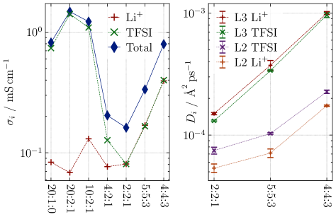
However, these simplified measures capture transport due to self-diffusion only and are unable to consider ion correlations.74, 78 The calculation of the overall ionic conductivity including ion correlations necessitates a longer simulation time to allow better statistical analysis. Nonetheless, a promising increase of the ideal conductivities for cations can be observed for systems with a high salt loading and additional \ceTHF. The :: systems additionally exhibit approximately equal contributions of anions and cations to the conductivity which results in an increased \ceLi+ transference number when compared to systems with less salt. A superior lithium transference number has also been attested experimentally.34 However, a simple quantitative comparison between these conductivities and the corresponding experimental values is not possible because of differing conditions: The higher temperatures in the simulations should increase the simulated conductivities in comparison to the experiment. Contrary the much thicker salt layer between the PEO domains in the experiment would increase the experimental values.
In order to get a better understanding of the nature of the cation transport the lateral was calculated in three distinct layers within the bilayer (cf. LABEL:fig:si_msd_layer): Layer 1 contains the interface between PS and PEO domains. Layer 2 hosts the bulk of the PEO and layer 3 contains the PEO–chain ends as well as the central salt layer. The ions are assigned to the appropriate layer based on their position at beginning of the time interval . This observation reveals that the displacements in layer 1 and 2 are comparable to each other. However, the displacement in layer 3 is much larger than in the other layers. The slower movement of the cations between the polymer might be caused by the slower movement and higher viscosity of the polymer itself in addition to the strong coordination between \ceLi+ and PEO.
Furthermore, the lateral diffusion coefficients in the layers can be calculated for both ion species based on the lateral . Since layer 1 contains fewer ions than the other two layers the diffusion coefficient in this layer is more susceptible for statistical fluctuations. Consequently, the diffusion coefficients are calculated only for layers 2 and 3 which accommodate most of the ions. The resulting values for the :: systems are shown in Figure 8 (right) and reflect the observations made above (see also SI LABEL:tab:si_diff_ions_layer). In all :: systems a maximal diffusion coefficient is observed for both ion species in layer 3 and the increase caused by additional \ceTHF is more pronounced in this central layer. But, most importantly, there is another difference between the layer that contains most of the polymer chains (i.e. layer 2) and the central salt–rich layer (i.e. layer 3): In layer 2 the anionic diffusion coefficient is always larger than the cationic diffusion coefficient. Contrary in layer 3 the cationic diffusion coefficient is equal to or larger than the anionic diffusion coefficient in all :: systems. This again can be attributed to the strong coordination between PEO chains and cations in layer 2 which hinders cationic movement.
As a consequence the salt–rich layer in the middle of the bilayer seems to play an important role in facilitating a high ionic conductivity and a large cationic transference number. Most likely, this is even more pronounced in the experimental systems which have a much thicker salt layer. In recent years the concept of “solvent–in–salt” electrolytes is being actively explored again because an unusually high concentration of salt promises improved electrochemical stability of the electrolyte, advantageous electrode interface properties, and high lithium transference numbers. 79, 80, 81, 82 Super–concentrated block copolymer systems as discussed in this work might provide a way to combine those electrochemical advantages with additional mechanical rigidity. These findings motivate future work on the transport in such systems.
4 Conclusion
In the present study, we elucidated the structural properties of lamellar BCPs with unusually short PEO chains and high \ceLiTFSI salt loadings. It was found that increasing the salt concentration from 10:2:1 to 4:2:1 (i.e. EO:\ceLi+:\ceTHF) results in a change of the cation–coordination environment. A steep drop of the number of coordinating PEO oxygen atoms and an increase of coordinating \ceTFSI oxygens has been observed in this case. The 4:2:1 system exhibits a fraction of more than half of all cations that are no longer coordinated by any PEO chain. Most notably, this change in coordination is not only caused by a swelling of the PEO domain but also by the formation of a salt–rich layer in the middle of the bilayer. Starting from intermediate salt concentrations, the systems show the retraction of PEO from this central layer. Consequently, cations are coordinated by \ceTFSI and \ceTHF exclusively in the middle. The added salt also causes stretching of the PEO chains in order to accommodate more cations per polymer chain. As a result, the number of \ceLi+ per polymer chain strongly increases. A similar increase in coordination is observed with respect to the anions as well. Since multiple cations coordinate a single anion and vice versa, a network–like structure of salt is formed between the polymer chains. In the limit of large salt concentrations the majority of cations is part of a single large cluster. Additional \ceTHF is able to partially break up this structure by removing \ceTFSI from highly coordinated cations.
Most importantly, systems with high salt concentrations exhibit remarkably high cationic mobility located in the central salt–rich layer unraveling the microscopic origin of the experimental observations. Unlike typical PEO–based SPEs in which the anions show much higher diffusion coefficients, the diffusion coefficients are approximately equal for both anions and cations. This qualitatively agrees with the high cationic transference numbers found in the experiment. Since the PEO chains are immobilized by the high salt loadings, we conclude that this cation transport is decoupled from the polymer motion. A key contribution of this work is that the cation transport is facilitated by the \ceLiTFSI network in the central salt layer instead. Furthermore, the ion transport can be strongly improved by adding \ceTHF. In the future other solvents with better properties, e.g. higher electrochemical stability, can be investigated as a \ceTHF substitute. Thus, the tuning of transport properties can be achieved by optimizing solvents in experiments.
References
- 1 Dias, F. B.; Plomp, L.; Veldhuis, J. B. Trends in Polymer Electrolytes for Secondary Lithium Batteries. 88, 169–191, DOI: 10.1016/S0378-7753(99)00529-7
- 2 Fergus, J. W. Ceramic and Polymeric Solid Electrolytes for Lithium-Ion Batteries. 195, 4554–4569, DOI: 10.1016/j.jpowsour.2010.01.076
- 3 Ngai, K. S.; Ramesh, S.; Ramesh, K.; Juan, J. C. A Review of Polymer Electrolytes: Fundamental, Approaches and Applications. 22, 1259–1279, DOI: 10.1007/s11581-016-1756-4
- 4 Placke, T.; Kloepsch, R.; Dühnen, S.; Winter, M. Lithium Ion, Lithium Metal, and Alternative Rechargeable Battery Technologies: The Odyssey for High Energy Density. 21, 1939–1964, DOI: 10.1007/s10008-017-3610-7
- 5 Xu, W.; Wang, J.; Ding, F.; Chen, X.; Nasybulin, E.; Zhang, Y.; Zhang, J.-G. Lithium Metal Anodes for Rechargeable Batteries. 7, 513–537, DOI: 10.1039/C3EE40795K
- 6 Lin, D.; Liu, Y.; Cui, Y. Reviving the Lithium Metal Anode for High-Energy Batteries. 12, 194–206, DOI: 10.1038/nnano.2017.16
- 7 Rosso, M.; Gobron, T.; Brissot, C.; Chazalviel, J.-N.; Lascaud, S. Onset of Dendritic Growth in Lithium/Polymer Cells. 97-98, 804–806, DOI: 10.1016/S0378-7753(01)00734-0
- 8 Aurbach, D.; Zinigrad, E.; Cohen, Y.; Teller, H. A Short Review of Failure Mechanisms of Lithium Metal and Lithiated Graphite Anodes in Liquid Electrolyte Solutions. 148, 405–416, DOI: 10.1016/S0167-2738(02)00080-2
- 9 Bieker, G.; Winter, M.; Bieker, P. Electrochemical in Situ Investigations of SEI and Dendrite Formation on the Lithium Metal Anode. 17, 8670–8679, DOI: 10.1039/C4CP05865H
- 10 Cheng, X.-B.; Zhang, R.; Zhao, C.-Z.; Wei, F.; Zhang, J.-G.; Zhang, Q. A Review of Solid Electrolyte Interphases on Lithium Metal Anode. 3, 1500213, DOI: 10.1002/advs.201500213
- 11 Xu, K. Nonaqueous Liquid Electrolytes for Lithium-Based Rechargeable Batteries. 104, 4303–4418, DOI: 10.1021/cr030203g
- 12 Sasaki, Y. Organic Electrolytes of Secondary Lithium Batteries. 76, 2–15, DOI: 10.5796/electrochemistry.76.2
- 13 Deng, D. Li-Ion Batteries: Basics, Progress, and Challenges. 3, 385–418, DOI: 10.1002/ese3.95
- 14 Wright, P. V. Electrical Conductivity in Ionic Complexes of Poly(Ethylene Oxide). 7, 319–327, DOI: 10.1002/pi.4980070505
- 15 Berthier, C.; Gorecki, W.; Minier, M. Microscopic Investigation of Ionic Conductivity in Alkali Metal Salt–Poly(Ethylene Oxide) Adducts. 11, 91–95, DOI: 10.1016/0167-2738(83)90068-1
- 16 Armand, M. B. Polymer Electrolytes. 16, 245, DOI: 10.1146/annurev.ms.16.080186.001333
- 17 Armand, M. Polymers with Ionic Conductivity. 2, 278–286, DOI: 10.1002/adma.19900020603
- 18 Donoso, J. P.; Bonagamba, T. J.; Panepucci, H. C.; Oliveira, L. N.; Gorecki, W.; Berthier, C.; Armand, M. Nuclear Magnetic Relaxation Study of Poly(Ethylene Oxide)–Lithium Salt Based Electrolytes. 98, 10026–10036, DOI: 10.1063/1.464435
- 19 Watanabe, M.; Sanui, K.; Ogata, N.; Kobayashi, T.; Ohtaki, Z. Ionic Conductivity and Mobility in Network Polymers from Poly(Propylene Oxide) Containing Lithium Perchlorate. 57, 123–128, DOI: 10.1063/1.335386
- 20 Shi, J.; Vincent, C. The Effect of Molecular Weight on Cation Mobility in Polymer Electrolytes. 60, 11–17, DOI: 10.1016/0167-2738(93)90268-8
- 21 Monroe, C.; Newman, J. Dendrite Growth in Lithium/Polymer Systems. 150, A1377, DOI: 10.1149/1.1606686
- 22 Monroe, C.; Newman, J. The Effect of Interfacial Deformation on Electrodeposition Kinetics. 151, A880, DOI: 10.1149/1.1710893
- 23 Monroe, C.; Newman, J. The Impact of Elastic Deformation on Deposition Kinetics at Lithium/Polymer Interfaces. 152, A396, DOI: 10.1149/1.1850854
- 24 Young, W.-S.; Albert, J. N. L.; Schantz, A. B.; Epps, T. H. Mixed-Salt Effects on the Ionic Conductivity of Lithium-Doped PEO-Containing Block Copolymers. 44, 8116–8123, DOI: 10.1021/ma2013157
- 25 Young, W.-S.; Kuan, W.-F.; Epps, T. H. Block Copolymer Electrolytes for Rechargeable Lithium Batteries. 52, 1–16, DOI: 10.1002/polb.23404
- 26 Panday, A.; Mullin, S.; Gomez, E. D.; Wanakule, N.; Chen, V. L.; Hexemer, A.; Pople, J.; Balsara, N. P. Effect of Molecular Weight and Salt Concentration on Conductivity of Block Copolymer Electrolytes. 42, 4632–4637, DOI: 10.1021/ma900451e
- 27 Soo, P. P. Rubbery Block Copolymer Electrolytes for Solid-State Rechargeable Lithium Batteries. 146, 32, DOI: 10.1149/1.1391560
- 28 Niitani, T.; Shimada, M.; Kawamura, K.; Dokko, K.; Rho, Y.-H.; Kanamura, K. Synthesis of Li+ Ion Conductive PEO-PSt Block Copolymer Electrolyte with Microphase Separation Structure. 8, A385, DOI: 10.1149/1.1940491
- 29 Singh, M.; Odusanya, O.; Wilmes, G. M.; Eitouni, H. B.; Gomez, E. D.; Patel, A. J.; Chen, V. L.; Park, M. J.; Fragouli, P.; Iatrou, H.; Hadjichristidis, N.; Cookson, D.; Balsara, N. P. Effect of Molecular Weight on the Mechanical and Electrical Properties of Block Copolymer Electrolytes. 40, 4578–4585, DOI: 10.1021/ma0629541
- 30 Hallinan, D. T.; Mullin, S. A.; Stone, G. M.; Balsara, N. P. Lithium Metal Stability in Batteries with Block Copolymer Electrolytes. 160, A464–A470, DOI: 10.1149/2.030303jes
- 31 Matsen, M. W.; Bates, F. S. Block Copolymer Microstructures in the Intermediate-Segregation Regime. 106, 2436–2448, DOI: 10.1063/1.473153
- 32 Ganesan, V.; Pyramitsyn, V.; Bertoni, C.; Shah, M. Mechanisms Underlying Ion Transport in Lamellar Block Copolymer Membranes. 1, 513–518, DOI: 10.1021/mz300051x
- 33 Dörr, T. S.; Pelz, A.; Zhang, P.; Kraus, T.; Winter, M.; Wiemhöfer, H.-D. An Ambient Temperature Electrolyte with Superior Lithium Ion Conductivity Based on a Self-Assembled Block Copolymer. 24, 8061–8065, DOI: 10.1002/chem.201801521
- 34 Pelz, A.; Dörr, T. S.; Zhang, P.; de Oliveira, P. W.; Winter, M.; Wiemhöfer, H.-D.; Kraus, T. Self-Assembled Block Copolymer Electrolytes: Enabling Superior Ambient Cationic Conductivity and Electrochemical Stability. 31, 277–285, DOI: 10.1021/acs.chemmater.8b04686
- 35 Abraham, M. J.; Murtola, T.; Schulz, R.; Páll, S.; Smith, J. C.; Hess, B.; Lindahl, E. GROMACS: High Performance Molecular Simulations through Multi-Level Parallelism from Laptops to Supercomputers. 1-2, 19–25, DOI: 10.1016/j.softx.2015.06.001
- 36 Martínez, L.; Andrade, R.; Birgin, E. G.; Martínez, J. M. PACKMOL: A Package for Building Initial Configurations for Molecular Dynamics Simulations. 30, 2157–2164, DOI: 10.1002/jcc.21224
- 37 Chu, W.; Qin, J.; de Pablo, J. J. Ion Distribution in Microphase-Separated Copolymers with Periodic Dielectric Permittivity. 51, 1986–1991, DOI: 10.1021/acs.macromol.7b02508
- 38 Gilbert, J. B.; Luo, M.; Shelton, C. K.; Rubner, M. F.; Cohen, R. E.; Epps, T. H. Determination of Lithium-Ion Distributions in Nanostructured Block Polymer Electrolyte Thin Films by X-Ray Photoelectron Spectroscopy Depth Profiling. 9, 512–520, DOI: 10.1021/nn505744r
- 39 Nosé, S. A Unified Formulation of the Constant Temperature Molecular Dynamics Methods. 81, 511–519, DOI: 10.1063/1.447334
- 40 Hoover, W. G. Canonical Dynamics: Equilibrium Phase-Space Distributions. 31, 1695–1697, DOI: 10.1103/PhysRevA.31.1695
- 41 Parrinello, M.; Rahman, A. Polymorphic Transitions in Single Crystals: A New Molecular Dynamics Method. 52, 7182–7190, DOI: 10.1063/1.328693
- 42 Darden, T.; York, D.; Pedersen, L. Particle Mesh Ewald: An N log( N ) Method for Ewald Sums in Large Systems. 98, 10089–10092, DOI: 10.1063/1.464397
- 43 Essmann, U.; Perera, L.; Berkowitz, M. L.; Darden, T.; Lee, H.; Pedersen, L. G. A Smooth Particle Mesh Ewald Method. 103, 8577–8593, DOI: 10.1063/1.470117
- 44 Jorgensen, W. L.; Maxwell, D. S.; Tirado-Rives, J. Development and Testing of the OPLS All-Atom Force Field on Conformational Energetics and Properties of Organic Liquids. 118, 11225–11236, DOI: 10.1021/ja9621760
- 45 Åqvist, J. Ion-Water Interaction Potentials Derived from Free Energy Perturbation Simulations. 94, 8021–8024, DOI: 10.1021/j100384a009
- 46 Mongelli, G. F. Critical Polyalkane, Polyether, and Polysilicone Structure Differences: Consideration of Polymer Forces from the OPLS-AA Standpoint. 05, DOI: 10.4172/2169-0022.1000313
- 47 Lemkul, J. A.; Allen, W. J.; Bevan, D. R. Practical Considerations for Building GROMOS-Compatible Small-Molecule Topologies. 50, 2221–2235, DOI: 10.1021/ci100335w
- 48 Torres-Knoop, A.; Heinen, J.; Krishna, R.; Dubbeldam, D. Entropic Separation of Styrene/Ethylbenzene Mixtures by Exploitation of Subtle Differences in Molecular Configurations in Ordered Crystalline Nanoporous Adsorbents. 31, 3771–3778, DOI: 10.1021/acs.langmuir.5b00363
- 49 Gouveia, A. S. L.; Bernardes, C. E. S.; Tomé, L. C.; Lozinskaya, E. I.; Vygodskii, Y. S.; Shaplov, A. S.; Lopes, J. N. C.; Marrucho, I. M. Ionic Liquids with Anions Based on Fluorosulfonyl Derivatives: From Asymmetrical Substitutions to a Consistent Force Field Model. 19, 29617–29624, DOI: 10.1039/C7CP06081E
- 50 Leontyev, I. V.; Stuchebrukhov, A. A. Electronic Continuum Model for Molecular Dynamics Simulations of Biological Molecules. 6, 1498–1508, DOI: 10.1021/ct9005807
- 51 Shimizu, K.; Freitas, A. A.; Atkin, R.; Warr, G. G.; FitzGerald, P. A.; Doi, H.; Saito, S.; Ueno, K.; Umebayashi, Y.; Watanabe, M.; Canongia Lopes, J. N. Structural and Aggregate Analyses of (Li Salt + Glyme) Mixtures: The Complex Nature of Solvate Ionic Liquids. 17, 22321–22335, DOI: 10.1039/C5CP03414K
- 52 Thum, A.; Heuer, A.; Shimizu, K.; Canongia Lopes, J. N. Solvate Ionic Liquids Based on Lithium Bis(Trifluoromethanesulfonyl)Imide–Glyme Systems: Coordination in MD Simulations with Scaled Charges. 22, 525–535, DOI: 10.1039/C9CP04947A
- 53 Sethuraman, V.; Mogurampelly, S.; Ganesan, V. Multiscale Simulations of Lamellar PS–PEO Block Copolymers Doped with LiPF 6 Ions. 50, 4542–4554, DOI: 10.1021/acs.macromol.7b00125
- 54 Sethuraman, V.; Mogurampelly, S.; Ganesan, V. Ion Transport Mechanisms in Lamellar Phases of Salt-Doped PS–PEO Block Copolymer Electrolytes. 13, 7793–7803, DOI: 10.1039/C7SM01345K
- 55 Zhang, Z.; Krajniak, J.; Keith, J. R.; Ganesan, V. Mechanisms of Ion Transport in Block Copolymeric Polymerized Ionic Liquids. 8, 1096–1101, DOI: 10.1021/acsmacrolett.9b00478
- 56 Lifschitz, M.; Freed, K. F. Interfacial Behavior of Compressible Polymer Blends. 98, 8994–9013, DOI: 10.1063/1.464459
- 57 Huang, C.; Olvera de la Cruz, M. Adsorption of a Minority Component in Polymer Blend Interfaces. 53, 812–819, DOI: 10.1103/PhysRevE.53.812
- 58 Borodin, O.; Smith, G. D.; Henderson, W. Li+ Cation Environment, Transport, and Mechanical Properties of the LiTFSI Doped N-Methyl-N-Alkylpyrrolidinium+TFSI- Ionic Liquids. 110, 16879–16886, DOI: 10.1021/jp061930t
- 59 Borodin, O.; Smith, G. D. Mechanism of Ion Transport in Amorphous Poly(Ethylene Oxide)/LiTFSI from Molecular Dynamics Simulations. 39, 1620–1629, DOI: 10.1021/ma052277v
- 60 Li, Z.; Borodin, O.; Smith, G. D.; Bedrov, D. Effect of Organic Solvents on Li+ Ion Solvation and Transport in Ionic Liquid Electrolytes: A Molecular Dynamics Simulation Study. 119, 3085–3096, DOI: 10.1021/jp510644k
- 61 Lesch, V.; Li, Z.; Bedrov, D.; Borodin, O.; Heuer, A. The Influence of Cations on Lithium Ion Coordination and Transport in Ionic Liquid Electrolytes: A MD Simulation Study. 18, 382–392, DOI: 10.1039/C5CP05111H
- 62 Müller-Plathe, F.; van Gunsteren, W. F. Computer Simulation of a Polymer Electrolyte: Lithium Iodide in Amorphous Poly(Ethylene Oxide). 103, 4745–4756, DOI: 10.1063/1.470611
- 63 Borodin, O.; Smith, G. D. Molecular Dynamics Simulations of Poly(Ethylene Oxide)/LiI Melts. 1. Structural and Conformational Properties. 31, 8396–8406, DOI: 10.1021/ma980838v
- 64 Diddens, D.; Paillard, E.; Heuer, A. Improving the Lithium Ion Transport in Polymer Electrolytes by Functionalized Ionic-Liquid Additives: Simulations and Modeling. 164, E3225–E3231, DOI: 10.1149/2.0271711jes
- 65 Seo, D. M.; Borodin, O.; Balogh, D.; O’Connell, M.; Ly, Q.; Han, S.-D.; Passerini, S.; Henderson, W. A. Electrolyte Solvation and Ionic Association III. Acetonitrile-Lithium Salt Mixtures–Transport Properties. 160, A1061–A1070, DOI: 10.1149/2.018308jes
- 66 Dokko, K.; Watanabe, D.; Ugata, Y.; Thomas, M. L.; Tsuzuki, S.; Shinoda, W.; Hashimoto, K.; Ueno, K.; Umebayashi, Y.; Watanabe, M. Direct Evidence for Li Ion Hopping Conduction in Highly Concentrated Sulfolane-Based Liquid Electrolytes. 122, 10736–10745, DOI: 10.1021/acs.jpcb.8b09439
- 67 Milner, S. T. Polymer Brushes. 251, 905–914, DOI: 10.1126/science.251.4996.905
- 68 Young, W.-S.; Epps, T. H. Salt Doping in PEO-Containing Block Copolymers: Counterion and Concentration Effects. 42, 2672–2678, DOI: 10.1021/ma802799p
- 69 Nakamura, I.; Wang, Z.-G. Salt-Doped Block Copolymers: Ion Distribution, Domain Spacing and Effective Parameter. 8, 9356, DOI: 10.1039/c2sm25606a
- 70 Teran, A. A.; Balsara, N. P. Thermodynamics of Block Copolymers with and without Salt. 118, 4–17, DOI: 10.1021/jp408079z
- 71 Qin, J.; de Pablo, J. J. Ordering Transition in Salt-Doped Diblock Copolymers. 49, 3630–3638, DOI: 10.1021/acs.macromol.5b02643
- 72 Guth, E.; James, H. M. Elastic and Thermoelastic Properties of Rubber like Materials. 33, 624–629, DOI: 10.1021/ie50377a017
- 73 Wittmer, J. P.; Beckrich, P.; Meyer, H.; Cavallo, A.; Johner, A.; Baschnagel, J. Intramolecular Long-Range Correlations in Polymer Melts: The Segmental Size Distribution and Its Moments. 76, 011803, DOI: 10.1103/PhysRevE.76.011803
- 74 Borodin, O.; Smith, G. D. LiTFSI Structure and Transport in Ethylene Carbonate from Molecular Dynamics Simulations. 110, 4971–4977, DOI: 10.1021/jp056249q
- 75 Self, J.; Fong, K. D.; Persson, K. A. Transport in Superconcentrated LiPF 6 and LiBF 4 /Propylene Carbonate Electrolytes. 4, 2843–2849, DOI: 10.1021/acsenergylett.9b02118
- 76 Alvarado, J.; Schroeder, M. A.; Zhang, M.; Borodin, O.; Gobrogge, E.; Olguin, M.; Ding, M. S.; Gobet, M.; Greenbaum, S.; Meng, Y. S.; Xu, K. A Carbonate-Free, Sulfone-Based Electrolyte for High-Voltage Li-Ion Batteries. 21, 341–353, DOI: 10.1016/j.mattod.2018.02.005
- 77 Dong, D.; Sälzer, F.; Roling, B.; Bedrov, D. How Efficient Is Li + Ion Transport in Solvate Ionic Liquids under Anion-Blocking Conditions in a Battery? 20, 29174–29183, DOI: 10.1039/C8CP06214E
- 78 Borodin, O.; Smith, G. D. Li + Transport Mechanism in Oligo(Ethylene Oxide)s Compared to Carbonates. 36, 803–813, DOI: 10.1007/s10953-007-9146-1
- 79 Suo, L.; Borodin, O.; Gao, T.; Olguin, M.; Ho, J.; Fan, X.; Luo, C.; Wang, C.; Xu, K. "Water-in-Salt" Electrolyte Enables High-Voltage Aqueous Lithium-Ion Chemistries. 350, 938–943, DOI: 10.1126/science.aab1595
- 80 Qian, J.; Henderson, W. A.; Xu, W.; Bhattacharya, P.; Engelhard, M.; Borodin, O.; Zhang, J.-G. High Rate and Stable Cycling of Lithium Metal Anode. 6, 6362, DOI: 10.1038/ncomms7362
- 81 Chen, F.; Forsyth, M. Elucidation of Transport Mechanism and Enhanced Alkali Ion Transference Numbers in Mixed Alkali Metal–Organic Ionic Molten Salts. 18, 19336–19344, DOI: 10.1039/C6CP01411A
- 82 Borodin, O.; Self, J.; Persson, K. A.; Wang, C.; Xu, K. Uncharted Waters: Super-Concentrated Electrolytes. 4, 69–100, DOI: 10.1016/j.joule.2019.12.007