Free-energy landscapes of intrusion and extrusion of liquid in truncated and inverted truncated conical pores: implications to the Cassie-Baxter to Wenzel transition
Abstract
As the simplest model of transition between the superhydrophobic Cassie-Baxter (CB) and Wenzel (W) states of a macroscopic droplet sitting on a microscopically rough or corrugated substrate, a substrate whose surface is covered by identical truncated or inverted truncated conical pores is considered. The free energy landscapes of the intrusion and extrusion processes of a liquid into single pore are analyzed when the liquid is compressed or stretched so that the liquid phase is either stable or metastable relative to the vapor phase. Therefore, this model is also relevant to the stability of the superhydrophobic submerged substrates. In this study, the macroscopic classical capillary theory is adopted. Even within this simplified model, two simple geometries of truncated and inverted truncated cones lead to completely different free-energy landscapes. A simple criterion for the stability of the CB state based on Laplace pressure is shown not to be sufficient to understand the destruction and recovery of the CB state. The free-energy landscapes indicate that a gradual and an abrupt destruction of CB state is possible, which depends on the orientation of the conical pore and whether the liquid is compressed or stretched. The extensions of these theoretical results to more complex geometries are briefly discussed.
I Introduction
Intrusion and extrusion of a liquid in microscale and nanoscale pores is a fundamental problem of thermodynamics of liquid in confined space Debenedetti1996 ; Kelton2010 ; Lefevre2004 ; Guillemont2012 ; Tinti2017 . This problem is related to the wetting and drying of a small pore, and heterogeneous nucleation from a metastable liquid or vapor phase. Recently, there has been growing interests in addressing this problem because it is relevant to the engineering Verho2012 ; Bormashenko2015 ; Xue2016 ; Jiang2020 of the so called superhydrophobic (SHP) substrates, which are realized from the Cassie-Baxter (CB) state Cassie1944 of a surface. To fabricate an SHP Cassie-Baxter (SHP-CB) state, pores of various shapes randomly or regularly distributed are engraved artificially on the surface of the substrate to make the substrate rough. If these pores are completely dry and filled with vapor, the liquid on the surface is supported by the cushion formed by the vapor insides the pores. Furthermore, the substrate shows superhydrophobicity which is characterized by a contact angle larger than and a small contact angle hysteresis Verho2012 ; Bormashenko2015 ; Xue2016 ; Jiang2020
The superhydrophobicity exhibited by the substrate can deteriorate due to the wetting transition in a pore from a completely dry CB state to a completely wet Wenzel (W) Wenzel1936 state Verho2012 ; Bormashenko2015 ; Xue2016 ; Jiang2020 . In the W state, all the pores are completely wet and filled with liquid. Therefore, preventing the wetting transition of the pore is crucial to achieve a sustainable superhydrophbicity. For this reason, the CB to W wetting transition has attracted considerable attention for the last two decades. Moreover, the W to CB drying transition is important to understand the restoration of the SHP-CB state Verho2012 ; Checco2014 ; Singh2015 ; Amabili2016 ; Prakash2016 ; Jones2017 ; Giacomello2019 .
Early theoretical studies Marmur2003 ; Marmur2006 were based on the classical Cassie-Baxter model Cassie1944 and the Wenzel model Wenzel1936 of the apparent contact angle. In these models, the wettability represented by the intrinsic Young’s contact angle and the solid-liquid and solid-vapor surface areas, determines the apparent contact angle, which can be more hydrophobic or hydrophilic compared to the original Young’s contact angle. Later, not only the surface area but also the geometrical shape of the pore is found to be important Tuteja2007 ; Nosonovsky2007 ; Verho2012 ; Bormashenko2015 ; Amabili2015 ; Xue2016 ; Jiang2020 . The SHP-CB state can be stabilized by pinning a liquid-vapor interface (edge effect) at the inlet of a pore and it can be destroyed by the sagging mechanism Patanker2010 ; Papadopoulos2013 . However, the simple intrusion and extrusion of a liquid into a pore is found to be the most basic process of the transition between the CB and W states Verho2012 ; Checco2014 ; Singh2015 ; Amabili2016 ; Prakash2016 ; Jones2017 ; Giacomello2019 . Therefore, the knowledge of the free-energy landscape and the energy barrier Verho2012 ; Checco2014 ; Singh2015 ; Amabili2015 ; Amabili2016 ; Prakash2016 ; Jones2017 ; Giacomello2019 ; Whyman2011 ; Savoy2012 ; Giacomello2012 ; Bormashenko2013 ; Iwamatsu2016 , which separates both the CB and W states, would be crucial to understand the stability and recovery of the SHP-CB state.
So far, we have used the Cassie-Baxter (CB) state and the superhydrophobic Cassie-Baxter (SHP-CB) state interchangeably. From now on, we will use the CB state to represent the completely dry single pore and the SHP-CB state to represent the superhydrophobic state of substrate to distinguish between the wetting transition of the individual pore and that of the substrate.
In this paper, we theoretically study the free-energy landscape between the CB and W states of a single pore. In particular, we assume that the liquid volume above the substrate is large enough to model the CB to W wetting transition from the intrusion and extrusion of the liquid into a single pore. Therefore, our model can be used to study the stability of underwater superhydrophobicity of the substrate Marmur2006 ; Xue2016 ; Xiang2017 ; Jones2017 . We adopted the classical capillary model for truncated and inverted truncated conical pores, which are typical geometries to extract the effect of pore shape Whyman2011 ; Checco2014 ; Jones2017 ; Giacomello2019 . A detailed atomistic process, which is beyond the scope of our classical capillary model, will be studied only numerically using the atomic simulations Amabili2016 ; Giacomello2012 ; Savoy2012 ; Tinti2017 ; Jones2017 ; Prakash2016 , or the microscopic denisty functional theory Singh2015 ; Giacomello2019 . To make our model as simple as possible, we assume a flat liquid-vapor interface Nosonovsky2007 ; Bormashenko2013 . The line tension Guillemont2012 ; Bormashenko2013 ; Iwamatsu2016 ; Schimmele2007 ; Law2017 at the liquid-vapor-solid triple line is neglected. These two effects will be discussed briefly at the end of the next section
II Classic Capillary Model of Pore Wetting
II.1 Classical capillary model
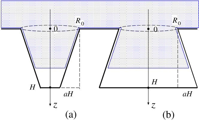
We consider the simplest wetting or drying transition by the intrusion and extrusion of liquid into a truncated conical pore Jiang2020 ; Bormashenko2013 ; Jones2017 ; Checco2014 , as shown in Fig. 1 (a), and an inverted truncated conical pore Jiang2020 ; Cao2007 ; Giacomello2019 with an overhanging structure, as shown in Fig. 1(b). We do not consider a more complex scenario of wetting and drying in which a liquid droplet or a vapor bubble nucleates independently at the corner of the pore wall Giacomello2012 ; Lv2015 ; Amabili2016 ; Jones2017 . The nucleation of a liquid droplet or a vapor bubble is possible when the vapor pressure is high, or the liquid is highly stretched and metastable under negative pressure Debenedetti1996 .
Free-energy landscape is obtained from the grand potential , which describes the thermodynamics of the liquid-vapor-solid (pore wall) system and depends on the chemical potential and on the temperature Amabili2016 ; Giacomello2012 , as:
| (1) |
by assuming a plausible transition pathway, where is the liquid volume inside the pore and is the pressure difference between the liquid and the vapor phase. In fact, the vapor pressure can be the air pressure by adding the partial pressure of various gases in air to the vapor pressure of liquid. Those gases trapped under the liquid will play an important role in the timescale of the CB to W transition which will be controlled by the diffusion of those gases. However, we will not consider the effect of gases or air explicitly since the free energy landscape remain the same as long as the total pressure difference remains the same Lv2015 ; Amabili2015 .
The first term in Eq. (1) given by
| (2) |
is the surface free energy, where and are the liquid-vapor surface tension, surface area, respectively, and is the solid-liquid (wet) surface area. The angle is the intrinsic Young’s contact angle defined by the Young’s equation
| (3) |
where and are the solid-vapor and solid-liquid surface tensions, respectively.
Bulk pressure difference between the liquid and vapor phases measures the relative stability of these two phases. A positive pressure difference corresponds to the pressurized compressed liquid, which is more stable than the metastable vapor, while a negative pressure difference corresponds to the stretched metastable liquid and the vapor is stable Debenedetti1996 ; Kelton2010 . A typical example of the former is the CB to W wetting transition on a underwater SHP substrate Bormashenko2015 ; Xue2016 ; Jiang2020 , and the latter is bubble nucleation, called cavitation, in stretched liquids Debenedetti1996 ; Kelton2010 .
We consider a pore with a rotationally symmetric shape around the axis, whose surface profile is given by
| (4) |
where is the opening radius of the pore and with represents the surface topology of the pore wall (Fig. 1).
In this work, we consider the simplest topology of a straight inclined wall with which gives a truncated cone with a narrowing radius (Fig. 1(a)) and an inverted truncated cone with a widening radius (Fig. 1(b)) characterized by
| (5) |
where is the slope of the wall. The negative sign corresponds to the narrowing pore shown in Fig. 1(a) and the positive sign corresponds to the widening pore shown in Fig. 1(b). The slope of a simple cylinder with a vertical wall is zero, i.e., .
The truncated cone becomes a simple cone Jones2017 ; Hauge1992 ; Reijmer1999 ; Malijevsky2015 when . This conical pore has been attracted special attentions Hauge1992 ; Reijmer1999 ; Malijevsky2015 since the wetting transition called the filling transition can occur. Due to the special geometry of the two-dimensional wedge and the three-dimensional cone, the cost of the surface free energy to move a flat liquid-vapor interface vanishes. Then, the interface will be delocalized and move to infinity if the liquid and the vapor phases are thermodynamic equilibrium. The thickness of the liquid layer adsorbed at the bottom of the wedge or cone will grow to infinity, and the complete wetting transition is realized. Since the contact angle between the flat interface and the pore wall remains finite, this complete wetting transition with non-zero contact angle is called filling transition Hauge1992 ; Reijmer1999 ; Malijevsky2015 .
In fact, the same filling transition can occur in our truncated cone when the liquid-vapor interface becomes flat. Therefore, the filling transition from the bottom of truncated cone can occur at exactly the same contact angle as in the simple cone. Similarly the intrusion of liquid from the top of turncated cone occurs without the cost of surface free energy. However, those transiton occurs at the liquid-vapor thermodynamic equilibrium. Although, those wetting transition can also destroy CB state Amabili2016 ; Jones2017 ; Giacomello2012 , we will concentrate on the simple intrusion and extrusion of liquid under the thermodynamic non-equilibrium condition by the compression or the depression of liquid.
We consider the free-energy landscape of the liquid intrusion in (or extrusion from) the pore by assuming the following. (1) The pinning of the liquid meniscus at the edge of the pore opening is not considered Patanker2010 ; Papadopoulos2013 , (2) the liquid does not condense separately at the pore bottom Giacomello2012 ; Jones2017 ; Kim2018 , and (3) the liquid-vapor meniscus is flat and horizontal Nosonovsky2007 ; Bormashenko2013 . Corrections due to non-flat meniscus and line tension at the triple line will be qualitatively considered later.
Our model, however, is too simplified for hydrophilic substrates because the pore wall is always wet and covered by a thin liquid layer Reijmer1999 . Also, the assumption of a flat meniscus is less accurate as the contact angle is low. The interaction between the intruding liquid with the wetting layer enhanced by the curved meniscus will make our model less reliable, in particular, in the late stage of wetting when the pore is almost filled by the liquid.
We first consider the narrowing pore when the position of the liquid-vapor meniscus in the pore is (see Fig. 1). The liquid volume in Eq. (1) is given by
| (6) |
and the solid-liquid and the liquid-vapor surface areas are given by
| (7) | |||||
and
| (8) |
which gives the grand potential
| (9) |
from Eq. (1) with the scaled free energy
| (10) | |||||
where
| (11) |
and
| (12) |
Therefore, the free-energy landscape is characterized by the scaled pressure , and the shape of the pore is characterized by two parameters and , which represents the steepness of the wall, and the depth of the pore relative to the size of the opening, respectively (see Fig. 1).
It is straightforward to stud;y the inverted truncated cone with a widening radius (Fig. 1(b)) characterized by
| (13) |
from Eq. (5). We can use the formulaes derived above for the inverted truncated cone with a widening radius by changing the sign of to negative. A positive () corresponds to the narrowing pore and a negative alpha () to the widening pore.
As the reference state, we consider the CB state when , whose free-energy is
| (14) |
and the free-energy difference is
| (15) |
When the CB state is the most stable state and when the CB state would be metastable. The scaled free energy from Eq. (10) becomes a cubic polynomial of
| (16) |
where
| (17) | |||||
| (18) | |||||
| (19) |
Although, the free energy described in Eq. (9) is correct as long as the liquid-vapor interface does not touch the pore bottom at . Once the liquid-vapor meniscus reaches the pore bottom, the free energy of the filled state given in Eqs. (9) and (10) does not represent the free energy of the correct W state since the wetting of the pore bottom is not considered. Therefore, our model assumes that the bottom surface is covered with a microscopic vapor layer, which might be true only when the bottom surface is strongly hydrophobic. We call the state characterized by the free energy in Eqs. (9)-(19) with as the filled (F) state to distinguish it from the W state. To consider the W state, we add the following correction
| (20) |
to the free-energies in Eqs. (9) and (10), where is the liquid-vapor surface area at the bottom given by
| (21) |
from Eq. (8). Therefore, we have to add the following correction
| (22) |
to the scaled free energy of the F state to obtain the scaled free energy of W state:
| (23) |
The correction can be interpreted as the adsorption energy of liquid at the bottom wall. Apparently the adsorption energy is always negative since the liquid-vapor interface disappears. This adsorption energy vanishes only when the substrate is SHP with . The F state always has higher free energy than the W state since . Since the F state always acts as the free-energy barrier for the W state, the CB to W and the F to W transitions are always irreversible in our capillary model.
Therefore, the transition to the W state cannot be described properly in our model because the free energy is singular and jumps at Patanker2004 ; Checco2014 . A more microscopic description Checco2014 ; Jones2017 ; Giacomello2012 ; Kim2018 than the macroscopic capillary model to trace the process of wetting of the bottom wall is necessary to describe the W state.
It is also possible, to study the final stage of wetting or the initial state of dewetting of the pore bottom using the classical capillary model by assuming the liquid or vapor nucleation, for example, from the bottom corner of the pore Lv2015 ; Giacomello2019 ; Kim2018 . In particular, the macroscopic theory of the filling transition Hauge1992 ; Reijmer1999 ; Malijevsky2015 can be applicable when the pore is rectangular and the bottom corner is the wedge formed by three orthogonal planes. In our work, however, We only focus on the global free-energy landscape between the CB and F states.
II.2 Critical pressure and critical Young’s contact angle
The stability limit of the SHP-CB state is determined from or at , which gives the critical pressure :
| (24) |
which is written as
| (25) |
using the original unit from Eq. (12). When the pore is a cylinder with straight vertical wall, we obtain the well known formula of the force balance of the Laplace pressure
| (26) |
by setting in Eq. (25).
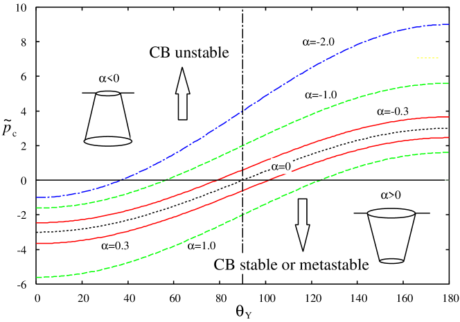
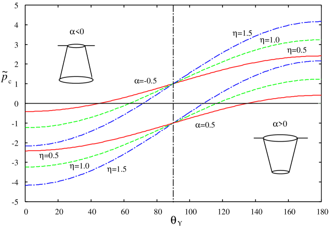
Figure 2 shows the critical pressure as a function of Young’s contact angle for various shape factors when (). The SHP-CB state becomes unstable when . The submerged pore under the compressed pressurized liquid corresponds to , while that under the decompressed metastable stretched liquid corresponds to . The critical pressure becomes positive, i.e., only when (critical Young’s contact angle), where
| (27) |
is determined from in Eq. (24). This critical angle is the lower-bound of for which the CB state is stable under the compressed liquid since the CB state is stable as long as (Fig. 2). This critical angle is alway larger than in the narrowing pore with , while it is always smaller than in the widening pore with in Fig. 2 (see also Fig. 3 ).
Therefore, a hydrophobic surface with is always necessary to achieve the SHP-CB state under the compressed liquid in the narrowing pore, while even a hydrophilic surface with is possible in the widening pore Xue2016 ; Marmur2006 . Further, the larger the magnitude of the slope the higher the critical pressure in the widening pore. Therefore, an ink-bottle shape with a narrow neck and a wide bottom would be favorable for the stability of the SHP-CB state Xue2016 ; Jiang2020 ; Marmur2006 .
Figure 2 shows the critical pressure as a function of for various pore depths when and . The critical pressure is more sensitive to when the parameter is large or the pore is deep. Apparently, a deep () widening pore () of hydrophobic substrate () is the most favorable to increase the critical pressure .
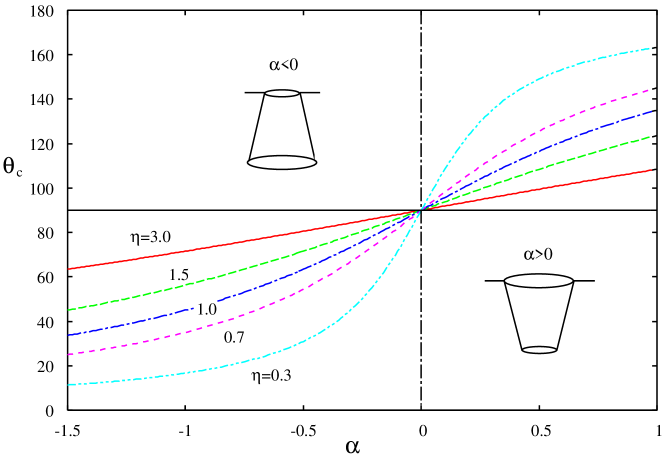
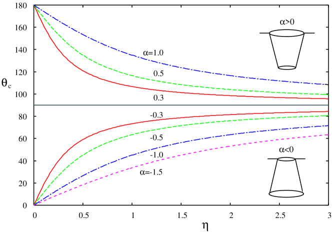
Figure 3 shows the critical contact angle as a function of the shape factor for varying depths . The critical pressure becomes positive when . The critical contact angle is always larger than when , while it can be smaller than when . Therefore an inverted truncated cone () can sustain the CB state even when the substrate is hydrophilic with . The critical angle is less sensitive to when the pore is deep (e.g., ) while it is more sensitive to when the pore is shallow (e.g., ).
Figure 3 shows the critical contact angle as a function of the pore depth of . Apparently for and for . A shallow (small ) inverted truncated pore () with a large is favorable to reduce and stabilize the CB state under compressed liquid even when the substrate is hydrophilic.
II.3 Free energy landscape
The critical pressure and, the critical contact angle only indicate the stability of the CB state. It does not necessarily mean that when , the CB state is absolutely unstable and the completely wet W state is absolutely stable. For instance, it could be possible to obtain an incompletely filled pore. Moreover, even when the CB state loses its stability, it can remain metastable through a free-energy barrier. Therefore, the information on the free-energy landscape and the free-energy barrier between the CB and the W states would be necessary to evaluate the stability of the CB state. This would be helpful in designing sustainable SHP.
Since the free-energy difference in Eq. (16) is a cubic polynomial of given by
| (28) |
it has two extrema at and determined from . They are
| (29) |
which is unphysical because when and when , and
| (30) |
which is a physically meaningful extremum, i.e., if when and when . Therefore, the free energy in Eq. (28) has only one extremum at where the free energy becomes
| (31) |
which corresponds to the minimum when and the maximum when . Note that when (CB state).
At the extremum given by Eq. (30), the radius of the circular contact line is given by
| (32) |
which gives an equation similar to that of the Laplace pressure
| (33) |
in the original unit in Eq. (12).
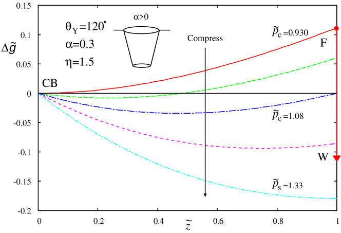
Figure 4 shows the free-energy landscape between (CB state) and (F state and not exactly the W state) of a truncated conical pore with a narrowing radius of and . Further, the pore wall is made up of a hydrophobic non-wettable substrate with . The free energy of the W sate is always lower than that of the F state by the amount from Eq. (22), which is large in the scale of Fig. 4.
By compressing the liquid from zero pressure, the CB state becomes unstable at the critical pressure . Even at this pressure, the free energy of the F state is positive (); however, the free energy of the W state becomes negative (). Therefore, the W state has a lower free energy as compared to that of the CB state. Therefore, the free-energy of the F state acts as the energy barrier to prevent the CB to W transition (Fig.4).
As the pressure increase, the liquid starts to intrude into the pore but does not completely fill the pore. Instead, the liquid-vapor meniscus is trapped at the free-energy minimum (Fig. 4) given by Eq. (30). With the further increased in pressure, the liquid further intrude into the pore. Then, the free energies at (CB state) and at (F state) become equal at when , which gives
| (34) |
Equation (34) does not represent the pressure when the free energies of the CB state and W states become equal. This pressure is determined from in Eq. (23), which gives
| (35) |
Note that we always have . The equality holds only when . Figure 4 indicates that the W state cannot be attained even at because the F state acts as the energy barrier.
Figures 4 and 5 indicate that there is a possibility of the first order phase transition to the W state not from the completely dry CB state but from the partially filled CB state at the free-energy minimum given by Eq. (30). The pressure where this transition become possible will be determined from from Eqs. (23) and (31), which leads to the cubic equation for the pressure and the solution which satisfies corresponds to the pressure at which the first order transition from the partially filled CB state to the completely filled W state take place. We will not consider this problem further and will concentrate on the global character of the free-energy landscape.
The depth of the free-energy minimum near can be estimated from Eq. (31) which gives at in the scaled unit and in the original unit (Eq. (15)). Suppose nm and mJm-1 (water), we then obtain J, which is two orders of magnitude larger than the thermal energy . As a result, the thermal fluctuation of the liquid-vapor interface would be small and the interface would be trapped at the free-energy minimum.
When the applied pressure increases beyond , the liquid-vapor interface moves toward ; however it is still trapped at the free-energy minimum given by Eq. (30). Finally, when the position of the minimum reaches the pore bottom and in Eq. (30), which is realized by the pressure given by
| (36) |
the CB state reaches the real stability limit; thus the F state with will be realized. Subsequently, the pore bottom would be wet, and the F to W transition would occur. Consequently, the CB to W transition would occur because the W state always has a lower free energy that the F state (). Hence, the pore would be completely filled and wet.
The pressure is higher for a larger (Eq. (36)) and becomes infinitely large for a conical-shaped pore Jones2017 with . The free-energy landscape in Fig. 4 provides a complete picture of the intrusion of the liquid into the truncated conical pore. In other words, it describes the collapse of the SHP-CB state from the applied pressure. The CB state does not collapse suddenly at , which is indicated by the classic formula in Eq. (25). Rather, the collapse occurs by the gradual intrusion of the liquid-vapor meniscus. The completely filled and wet W state might be realized at but not at . This collapse of the CB state is irreversible because the adsorption energy acts as the energy barrier in the W to F dewetting transition.
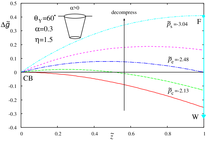
Figure 4 shows the free-energy landscape between (the CB state) and (the F state) of a truncated conical pore with a narrowing radius and made up of a hydrophilic wettable substrate with and . The free energy of the W sate is always lower than that of the F state by the amount obtained from Eq. (22), which has magnitude larger than that of the hydrophobic substrate in Fig. 4 (-0.245).
The convex free-energy landscape shown in Fig. 4 is completely different from the concave landscape in Fig. 4. When the liquid is weakly decompressed, the F state remains stable; however, the unstable CB state becomes metastable at . When the liquid is further decompressed, a free-energy barrier between the CB and F states starts to develop. The free energies of the CB and F states become equal at (Fig. 4). However, there remains a free-energy barrier of height similar in magnitude to the depth of the free-energy well shown in Fig. 4. Since the free energy of the W state is always lower than that of the CB state, the W state is stabler than the CB state at . As the pressure becomes more negative, the CB state becomes more stable compared to the F state; however, the W state remains the most stable.
Finally, the free-energy barrier between the CB and F states vanishes, and the F state has a higher free energy than that of the CB state at , which is similar to the spinodal of the first-order phase transition Debenedetti1996 ; Kelton2010 . However, the free energy of the W state is ; hence, the W sate is still more stable than the CB state. Therefore, the spontaneous transition from the W state to the CB state will not occur, and the SHP-CB state will not be recovered.
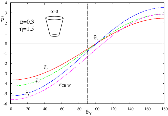
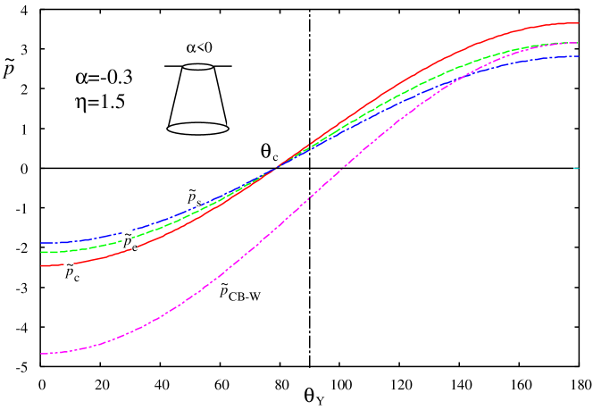
Figure 5 shows the three pressures , , and (Eqs. (24), (34) and (36)), which characterize the free-energy landscape, for the truncated cone with (Fig. 5) and the inverted truncated cone with (Fig. 5). These pressures are positive when and negative when . The former condition corresponds to the pore under the compressed liquid, and the latter condition corresponds to the pore under the decompressed liquid. The orders of these three pressures change at , which lead to the inverted free-energy landscape shown in Fig. 4 and 4. Moreover, the orders for the narrowing pore () and that for the widening pore are reversed, which will further lead to the inverted free-energy landscape for the inverted truncated cone, as shown in Fig. 6. In addition, figure 5 shows the pressure (Eq. (35)), where the free energies of the CB and the W states becomes equal.
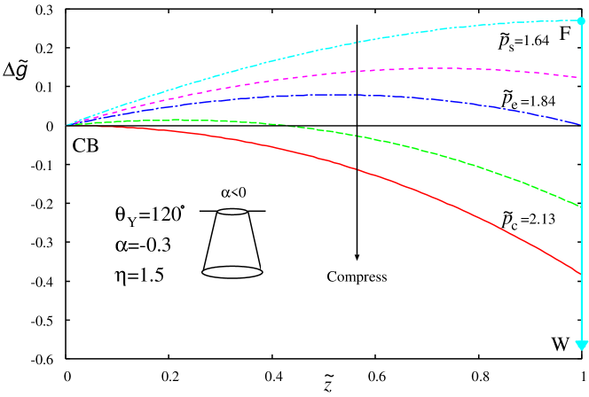
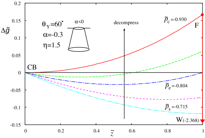
Figure 6 shows the free-energy landscape for the ink-bottle shaped inverted truncated conical pore with a widening radius of and . The pore wall is made up of a non-wettable substrate with . In this case, the critical Young’s contact angle is , therefore, the hydrophilic pore () can sustain the CB state under the positive pressure as far as . The evolution of convex free-energy landscape in Fig. 6 is completely different from concave one in Fig. 4; however, it is similar to the free-energy landscape in Fig. 4. The orders of the three pressures , , and are reversed (see also Fig. 5, upper tree lines). The free energy of the W state is lower than that of the F state by (Eq. (22)), which is almost the entire energy scale of Fig. 6.
When the pressure increases, the unstable filled F state at becomes metastable at while the CB state remains stable relative to the F state. In fact, the W state has a much lower free energy as compared to that of the CB state. As a result, the W sate is absolutely stable and the CB state is metastable. As the pressure is further increased, the free energy of the F state decreases and the free-energy barrier develops between the CB and the F states. When the applied pressure reaches , the free energies of the completely filled F and completely empty CB states become equal. However, the free-energy barrier exists between the CB and the F states. The magnitude of the free-energy barrier at in Fig. 6 and that at in Fig. 4 are on the same order of magnitude. Therefore, the CB state would remain stable compared to the F state as long as the free-energy barrier remains larger than the thermal energy.
Finally, at the critical pressure , the CB state becomes completely unstable and the F state is realized. Subsequently, the bottom surface becomes wet spontaneously and the completely filled W state is realized. In contrast to the narrowing pore in Fig. 4 where the CB state collapses continuously, the collapse would occur abruptly at in the widening pore in Fig. 6. The prediction of the critical pressure in Eq. (25) is correct in this widening pore.
Figure 6 shows the free-energy landscape for the wettable substrate with , and . The critical pressure and it is negative; hence, the liquid must be decompressed and metastable Debenedetti1996 ; Kelton2010 . The evolution of the free-energy landscape in Fig. 6 is very similar to that in Fig. 4. The free energy of the W state is lower than that of the F state by (from Eq. (22)), which is beyond the scale of Fig. 6.
Since the substrate is wettable, the W and F states are more stable than the CB state at a positive pressure. As the liquid is decompressed to a negative pressure, the F state becomes metastable at . As the liquid is further decompressed, a free-energy minimum appears between the F state at and the CB state at , which moves toward the CB state. Finally, when the pressure , the local minimum reaches the top of the pore at . Although the F state has a higher energy as compared to that of the CB state, the free energy of the W state is ; hence, the W state is more stable than the CB state. The CB state cannot be recovered simply by deep decompression. In fact, the adsorption energy always acts as the free energy barrier to prevent the W to F dewetting transition.
II.4 Discussion
When the size of the pore is in nanoscale, the line tension in addition to the surface tension might play some role in the evolution of free-energy landscape Schimmele2007 ; Guillemont2012 ; Bormashenko2013 ; Iwamatsu2016 ; Law2017 ; therefore, the line tension need to be included in the free energy, which is written as
| (37) |
instead of Eq. (2), where is the perimeter of the three-phase contact line. In our truncated conical pore with a narrowing radius, for example, the last term of Eq. (37) becomes
| (38) |
which gives a correction to the first order term of in the scaled free energy in Eq. (10), and Eq. (17) is modified to
| (39) |
with
| (40) |
If , the effect of line tension can be safely neglected. Suppose nm, mJm-1 (water), and N (typical magnitude), we find . Therefore, this effect can be safely neglected. Even when the effect of line tension cannot be neglected, the line tension only affects the critical pressure in Eq. (24) from Eq. (39). The line tension will not change the main characteristics of the free-energy landscape because it will remain a cubic polynomial of .
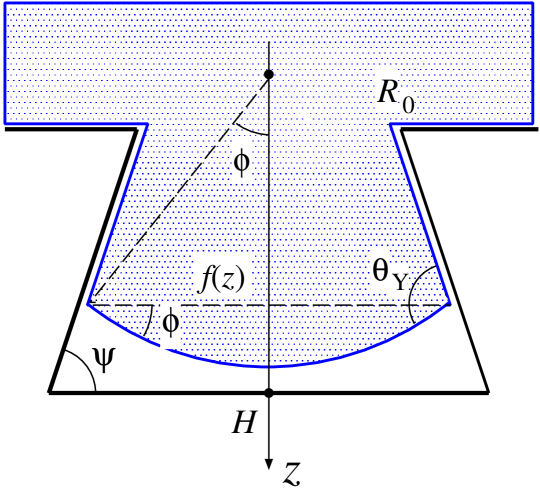
In our model we assumed a flat liquid-vapor interface Nosonovsky2007 ; Bormashenko2013 ; however, it is possible to consider a spherical surface. The volume collection due to the truncated sphere shown in Fig. 7 is given by
| (41) |
and the liquid-vapor surface area will be modified such that
| (42) |
where is the angle between the liquid-vapor meniscus and the horizontal plane (Fig. 7). It is related to Young’s contact angle through
| (43) |
where is the angle of the bottom corner of the pore (Fig. 7). Even with the two corrections in Eqs. (41) and (42), the free energy is still described by a cubic polynomial of . The qualitative feature of the free-energy landscapes in Figs. 4, 4 and 6, 6 will not change.
When the size of the pore is truly nanoscale, the disjoining pressure (DJP) or the surface potential has to be included Bormashenko2013 . Then, we need to determine the liquid-vapor meniscus by solving the Euler-Lagrange equation Checco2014 . A more microscopic approach, such as molecular simulations Tinti2017 ; Amabili2016 ; Prakash2016 ; Giacomello2012 or microscopic density functional calculation Singh2015 ; Giacomello2019 would also be necessary. Certainly, not only quantitative but also a qualitative difference between the microscopic calculations and our macroscopic model would emerge. For example, due to the DJP, the atomic-scale wetting film always exists Evans1985 ; Iwamatsu1996 ; Bormashenko2013b ; hence, the apparent pore space would be narrower. There is also a possibility to observe heterogeneous nucleation of droplets Giacomello2012 ; Jones2017 and bubbles Prakash2016 at the bottom corner of the pore. The singularity of the W state and the discontinuous transition from the F state to W state would be naturally resolved by the effect of the DJP. These topics are certainly important when the pore size is truly nanoscale and the pressure is high; however, they are beyond the scope of our macroscopic capillary model.
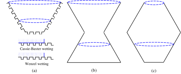
Finally, we consider the extension of our simplest conical pore models briefly. To achieve SHP state, it is well recognized that the hierarchical structure, which increases the solid-liquid surface area, would be advantageous when the substrate is hydrophobic Nosonovsky2007 ; Jiang2020 ; Bormashenko2013 ; Giacomello2016 ; Giacomello2019 . It is possible to extend our simplest model and introduce sub-structures Giacomello2019 as shown in Fig. 8(a). For instance, the wetting of these microscopic structures is modeled by the microscopic wetting models Cassie1944 ; Wenzel1936 (Fig. 8(a)) with the apparent averaged contact angles. If the vapor is trapped in those substructures and we can average the contact angle over the rough surface, the Young’s contact angle should be replaced by the apparent contact angle given by
| (44) |
of the traditional Cassie-Baxter (CB) model Cassie1944 ; Bormashenko2015 ; Giacomello2016 , where is the fraction of wet surface area. Alternatively, we assume that the liquid fill these substructures Whyman2011 . The Young’s contact angle should be replaced by the apparent contact angle given by
| (45) |
of the traditional Wenzel (W) model Wenzel1936 ; Bormashenko2015 ; Quere2002 , where is the so-called roughness factor. Then, Young’s contact angle of the previous subsections must be replaced by either or . Indeed, it is possible to consider a microscopic intermediate wetting state between the CB and the W models Bormashenko2015 .
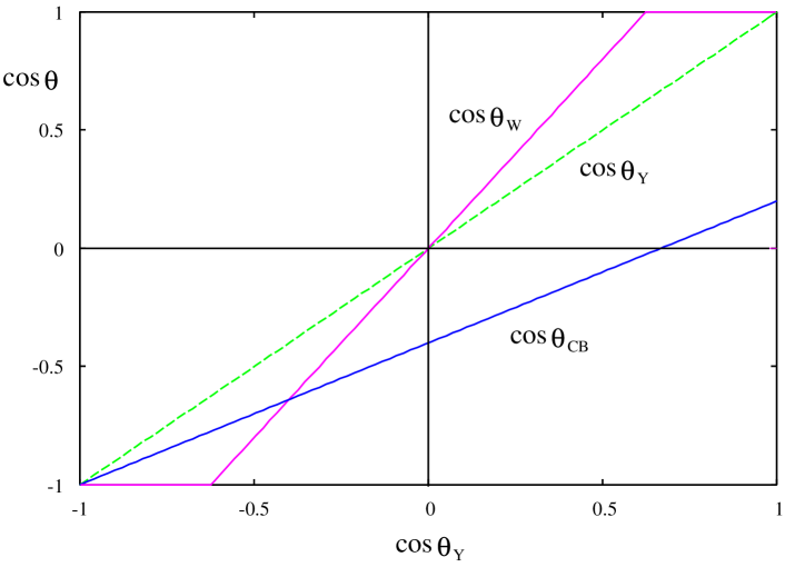
Therefore, an inherently hydrophobic pore wall with becomes more hydrophobic with Bormashenko2015 ; Quere2002 and Bormashenko2015 (Fig. 9). Both the CB and the Wenzel models of the micro-structures make the pore wall more hydrophobic; therefore, the models are advantageous for the stability of the SHP-CB state. In contrast, when the substrate is hydrophilic (), only the CB model of the pore wall makes the apparent contact angle more hydrophobic (); therefore, the stability of the SHP-CB state will be enhanced. Thus, the roughness of the pore wall or the so-called hierarchical structure could be advantageous to achieve the SHP-CB substrate particularly when the wall is intrinsically hydrophobic.
Of course, the prediction of the W and CB model needs to be considered carefully since the apparent contact angels in Eqs. 44 and 45 of the W and the CB models are the averaged angle which does not take into account the micro structure of the roughness. In fact, it is well recognized that the hydrophobic substrate from hydrophilic materials requires roughness with re-entrant structure Joly2009 ; Amabili2016 . The Wenzel and the Cassie-Baxter models are macroscopic model so that the range of applicability is certainly limited.
It is also possible to consider the reentrant structures shown in Fig. 8(b) and 8(c). The evolution of the free-energy landscape will be the combination of that of the interface-trapping in Figs. 4 and 6 and that of the barrier-crossing in Figs. 4 and 6. For example, the free-energy landscape for the hydrophobic re-entrant structure in Fig. 8(b) would be the combination of Fig. 4 and Fig. 6. Therefore, as the liquid intrudes into the pore, the liquid-vapor interface advances by the interface-trapping followed by the barrier-crossing. However, for the hydrophobic re-entrant structure in Fig. 8(c), the order of the free-energy landscape changes to that in Fig. 6 followed by Fig. 4.
Similarly, the free-energy landscape for the hydrophilic re-entrant structure in Fig. 8(b) would be the combination of Fig. 4 and Fig. 6. On the other hand, the free-energy landscape for the hydrophilic reentrant structure in Fig. 8(c) would be the combination of Fig. 6 and Fig. 4. Therefore, more complex free-energy landscape will be expected for the re-entrant structure whose components are simple truncated cones.
III Conclusion
In this study, we considered the intrusion and extrusion of liquid into a truncated conical pore Jiang2020 ; Bormashenko2013 ; Jones2017 and an inverted truncated conical pore Jiang2020 ; Cao2007 ; Giacomello2019 . The intrusion of liquid corresponds to the destruction of the superhydrophobic Cassie Baxter (SHP-CB) state, and the extrusion of liquid corresponds to the destruction of the Wenzel (W) state and the recovery of the SHP-CB state. We found that the simple criterion of the stability of CB state based on the classical Laplace pressure cannot describe the details of these processes.
In the truncated conical pore with hydrophobic substrate under the compressed liquid, the destruction of SHP-CB occurs gradually by the movement of the liquid-vapor interface as the liquid is pressurized. When the substrate is hydrophilic, and the liquid is decompressed, the recovery of the SHP-CB cannot occur since the adsorption energy of liquid on the bottom wall of the pore always prevent the dewetting.
In contrast, in the inverted truncated conical pore with hydrophobic substrate under the compressed liquid, the destruction of SHP-CB state occurs abruptly since the free-energy barrier exists. However, the recovery of SHP-CB state under the decompressed liquid cannot occur as the adsorption energy always prevent the dewetting. Therefore, the geometry of the pore will strongly influence the intrusion and extrusion processes of the liquid in the pore. These knowledge would be useful to understand and design functional superhydrophobic substrates.
Acknowledgements.
The author is grateful to the reviewers for their insightful commens and useful suggestions, in particular, about the singularity of the Wenzel state of this model. Their criticisms were helpful to shape the final version of this article..
References
- (1) P. G. Debenedetti, Metastable Liquids-Concepts and Principles, Princeton Univ. Press, Princeton 1996.
- (2) K. F. Kelton and A. L. Greer, Nucleation in Condensed Matter-Applications in Materials and Biplogy, Elsevier, Amsterdam 2010.
- (3) B. Lefevre, A. Saugey, J. L. Barrat, L. Bocquet, E. Charlaix, P. F. Gobin, and G. Vigier, Intrusion and extrusion of water in hydrophobic mesopores, J. Chem. Phys. 120, 4927 (2004).
- (4) L. Guillemont, T. Biben, A. Galarneau, G. Vigier, E. Charlaix, Activated drying in hydrophobic nanopres and the line tension of water, Proc. Natl. Acad. Sci. 109, 19557 (2012).
- (5) A. Tinti, A. Giacomello, Y. Grosu, and C. M. Casciola, Intrusion and extrusion of water in hydrophobic nanopores, Proc. Natl. Acad. Sci. 114, E10266 (2017).
- (6) T. Verho, J. T. Korhonen, L. Sainiemi, V. Jokinen, C. Bower, K. Franze, S. Franssila, P. Andrew, O, Ikkala, R. H. A. Ras, Reversible switching between superhydrophobic states on a hierarchically structured surface, Proc. Natl. Acad. Sci. 109, 10210 (2012).
- (7) E. Bormashenko, Progress in understanding wetting transitions on rough surfaces, Adv. Colloid Interface Sci. 222, 92 (2015).
- (8) M. Amabili, A. Giacomello, S. Meloni, and C. M. Casciola, Unraveling the Salvinia paradox: Desing principles for suberged superhydrophobicity, Adv. Mater. Interfaces 2, 1500248 (2015).
- (9) Y. Xue, P. Lv, H. Lin, H. Duan, Underwater Superhydrophobicity: Stability, Design and Regulation, and Application, Appl Mech. Rev. 68, 030803 (2016).
- (10) Y. Jiang, J. Liang, Z. Jiang, Y. Li, and C. Wen, Thermodynamic analysis on wetting states and wetting state transition of rough surfaces, Adv. Colloid Interface Sci. 278 102136 (2020).
- (11) A. B. D. Cassie and S. Baxter, Wettability of porous surfaces, Trans. Faraday Soc. 40, 546 (1944).
- (12) R. N. Wenzel, Resistance of solid surfaces to wetting by water, Ind. Eng. Chem. Res. 28, 988 (1936).
- (13) A. Checco, B. M. Ocko, A. Rahman, C. T. Black, M. Tasinkevychi, A. Giacomello, and S. Dietrich, Collapse and Reversibility of Superhydrophobic State on Nanotextured Surfaces, Phys. Rev. Lett. 112, 216101 (2014).
- (14) S. L. Singh, L. Schimmele, and S. Dietrich, Structure of simple liquids in contact with nanoscuptured surfaces, Phys Rev. E 91, 032405 (2015).
- (15) A. Amabili, E. Lisi, A. Giacomello, C. M. Casciola, Wetting and cavitation pathways on nanodecorated surfaces, Soft Matter 12, 3046 (2016).
- (16) S. Prakash, E. Xi, and A. J. Patel, Spontaneous recovery of superhyrophobicity of nanotextured surfaces, Proc. Natl. Acad. Sci. 113 5508 (2016).
- (17) P. R. Jones, A. T. Kirn, Y. D. Ma, D. T. Rich, and N. A. Patankar,The Thermodynamics of Restoring Underwater Superhydrophobicity, Langmuir 33 2911 (2017).
- (18) A. Giacomello, L. Schimmele, S. Dietrich, and M. Tasinkevych, Recovering superhydrophobicity in nanoscale and macroscale surface textures, Soft Matter 15 7462 (2019).
- (19) A. Marmur, Wetting on Hydrophobic Rough Surfaces: To Be Heterogeneous or Not To Be? Langmuir 19, 8343 (2003).
- (20) A. Marmur, Underwater Superhydrophobicity: Theoretical Feasibility, Langmuir 22, 1400 (2006).
- (21) A. Tuteja, W. Choi, M. Ma, J. M. Mabry, S. A. Mazzella, G. C. Rutledge, G. H. McKinley, R. E. Cohen, Designing Superoleophobic Surfaces, Science 318, 1618 (2007).
- (22) M. Nosonovsky, Multiscale Roughness and Stability of Superhydrophobic Biomimetic Interfaces, Langmuir 23, 3157 (2007).
- (23) N. A. Patanker, Consolidation of Hydrophobic Transition Criteria by Using an Approximate Energy Minimization Approach, Langmuir 26, 8941 (2010).
- (24) P. Papadopoulos, L. Mammen, X. Deng, D. Vollmer, H-J. Butt, How superhydrophobicity breaks down, Proc. Natl. Acad. Sci. 110, 3254 (2013).
- (25) G. Whyman and E. Bormashenko, How to make the Cassie wetting state stable?, Langmuir 27, 8171 (2011).
- (26) A. Giacomello, M. Chinappi, S. Meloni, C. M. Casciola, Metastable Wetting On Superhydrophobic Surfaces: Continuum and Atomistic Views of the Cassie- Baxter-Wenzel Transition, Phys. Rev. Lett. 109, 226102 (2012).
- (27) P. Lv, Y. Xue, H. Liu, Y. Shi, P. Xi, H. Lin, and H. Duan, Symmetric and asymmetric meniscus collapse in wetting transition on submerged structured surfaces, Langmuir 31, 1248 (2015).
- (28) E. S. Savoy, F. A. Escobedo, Simulation Study of Free-Energy Barriers in the Wetting Transition of an Oily Fluid on a Rough Surface with Reentrant Geometry, Langmuir 28, 16080 (2012).
- (29) E. Bormashenko, and G. Whyman, On the Role of the Line Tension in the Stability of Cassie Wetting, Langmuir 29, 5515 (2013).
- (30) M. Iwamatsu, Free-Energy Barrier of Filling a Spherical Cavity in the Presence of Line Tension: Implication to the Energy Barrier between the Cassie and Wenzel States on a Superhydrophobic Surface with Spherical Cavities, Langmuir 32 9475 (2016).
- (31) Y. Xiang, S. Huang, P. Lv, Y. Xue, Q. Su, H. Duan, Ultimate Stable Underwater Superhydrophobic State, Phys. Rev. Lett. 119, 134501 (2017).
- (32) L. Schimmele, M. Napiórkowski and S. Dietrich, Conceptual aspects of line tensions, J. Chem. Phys. 127, 164715 (2007).
- (33) B. M. Law, S. P. McBride, J. Y. Wang, H. S. Wi, G. Paneru, S. Betelu, B. Ushijima, Y. Takata, B. Flanders, F. Bresme, H. Matsubara, T. Takiue, and M. Aratono, Line tension and its influence on droplets and particles at surfaces, Prog. Surf. Sci. 92, 1 (2017).
- (34) L. Cao, H-H. Hu, D. Gao, Design and Fabrication of Micro-textures for Inducing a Superhydrophobic Behavior on Hydrophilic Materials. Langmuir 23, 4310 (2007).
- (35) E. H. Hauge, Macroscopic theory of wetting in a wedge, Phys. Rev. A 46, 4994 (1992).
- (36) K. Reijmer, S. Dietrich, and M. Napiórkowski, Filling transition for a wedge, Phys. Rev. E 60, 4027 (1999).
- (37) A. Malijevský and A. O. Parry, Fillling transition in acute and open wedges, Phys. Rev. E 91, 052401 (2015).
- (38) H. Kim, M. Y. Ha, and J. Jang, Wetting Transition of a Cylindrical Cavity Engraved on a Hydrophobic Surface, J. Phys. Chem. C 122 2122 (2018).
- (39) N. A. Patanker, Transition between superhydrophobic states on rough surfaces, Langmuir 20, 7097 (2004).
- (40) E. Bormashenko, V. Starov, Impact of surface forces on wetting of hierarchcal surfaces and contact angle hysteresis, Coll. Polym. Sci. 291, 343 (2013).
- (41) R. Evans and U. Marini Bettolo Marconi The role of weting films in capillary condensation and rise: Influence of long-range forces, Chem. Phys. Lett. 114, 415 (1985).
- (42) M. Iwamatsu and K. Horii, Capillary Condensation and Adhesion of Two Wetter Surfaces, J. Colloid Interface Sci. 182, 400 (1996).
- (43) A. Giacomello, L. Schimmele, S. Dietrich, and M Tasinkevych, Perpetual superhydrophobicity, Soft Matter 12, 8927 (2016).
- (44) D. Quéré, Rough ideas on wetting, Physica A 313, 32 (2002).
- (45) L. Joly and T. Biben, Wetting and friction on superhydrophobic surfaces, Soft Matter 5, 2549 (2009).