Characterization of Anomalous Forces in Dielectric Rotors
Abstract
We performed several measurements of anomalous forces on a dielectric rotor in operation, subjected to high voltage. The device operated under constant and intense angular velocity for each high voltage applied. The measurements were made in the similar way than an analogue magnetic gyroscope, by considering clockwise and counterclockwise rotations. We found that there are significant weight reduction on the device in the clockwise case, with one order of magnitude higher than the magnetic case. In addition, we detected a similar asymmetry in the observation of the effect, that is, there are smaller results for the anomalous forces in counterclockwise rotation. We also propose a theoretical model to explain the quantitative effect based on average values of macroscopic observables of the device rotation and concluded that it is consistent with the experimental results.
I Introduction
It is well known from literature that gyroscopes can be applied in a lot of technological applications, as in systems of localization on Earth (GPS) Bruckner ; Gao ; Najafi , in electronic games Allan ; Ionescu , in systems of navigation Venka and other cases, based on the physical properties related to the inertia of such devices. Besides, there is much interest in the research for new and more modern applications. In such a context, relevant reports have been made to the cases of gyroscopes in very small scales to be used like sensors Soder , in atomic scale Fang , in automotive cases to avoid vibrations Acar , in space navigation Roser and in other cases Antonello .
The applications involving gyroscopes are in general related to guiding, orientation or tracking the systems containing the device. However, in a relatively recent work Hay1 it was also investigated a new and novel property presented by Hayasaka’s group: their reduction of weight when they are subjected to high angular velocity and clockwise rotation. Further it was also found that there was an asymmetry in this property, that is, if the gyroscopes rotated in the opposite direction (counterclockwise) that weight reduction completely vanished. After that discovery, the same research group implemented measurements in a new setup in which the system also rotated in high angular frequency but in free fall Hay2 . It was found the same effect, that is, weight reduction for right rotation and null effect for the left one.
The novel results motivated other research groups to reproduce the effect. However, it was not found evidences of anomalous forces, as in the experimental works reported in Refs. Faller ; Quinn ; Nitschke . The negative experimental results obtained from those groups discouraged further investigations and hence anyone proceeded in a more profound investigation of the phenomenon, which remained forgotten by a relatively long time.
Despite of last reports, we started to investigate the phenomenon and reported our conclusions in our more recent work in the field Elio2019 , showing that all the other papers published after Hayasaka’s experimental work did not reproduce the same conditions reported in Ref. Hay1 , so that this motivated us to theoretically explain it and implement some experimental measurements on such setups to check by ourselves if gyroscopes could really present both effects, that is, the asymmetry for the two directions of rotation and the weight reduction in the device. Such a motivation was based on some relevant main reasons: the earlier experimental works used rotors made of brass, a material of low magnetic permeability in relation to the one used in Ref. Hay1 (silicon steel) and in the theoretical model proposed in Ref. Elio2019 the role of macroscopic collective effect of the magnetic dipoles constituting the rotor is more than fundamental. In addition to the material, some alternative experiments were similar to the former but they differed from it in some other important features: the masses of the gyroscope rotors were substantially larger; the gyroscopes were spun in closed containers, but the devices were not operating in vacuum, the maximum rotational frequencies were lower and the rotors were not electrically driven but air driven. So, it is surprising that, with so many differences, one could conclude that there was an effective reproduction of the original experiments. In fact, the many factors indicated could surely avoid the clear manifestation of so weak forces in the operation of the devices, so that the results could not be really reproduced.
The theoretical model presented in Ref. Elio2019 could successfully explain the magnitude of such forces for the setup described in Ref. Hay1 . In order to experimentally investigate the existence of such an effect in devices operating in rotation, we decided to establish a new experimental setup involving a rotor but considering a new physical configuration. As in our earlier works, we realized that magnetic dipoles and electric dipoles can both present such anomalies in the context of the generalized quantum entanglement (GQE), we implemented to perform some measurements of anomalous forces for a electrostatic material because in some of our previous works Elio2015 ; Elio2016a ; Elio2016b ; Elio2020a ; Elio2018d we verified strong magnitudes of forces involving this kind of material subjected to high voltage.The effect detected in the gyroscopes cannot be successfully associated to any conventional theory. So, we elaborated the theoretical description of such forces in the experiments by means of a theoretical model based on GQE, by considering as quantum witnesses the electric permittivity and as macroscopic observable the angular momentum of the dielectric rotors. The basic conjecture relies on that macroscopic observables can present influence in their magnitudes by a huge collection of microscopic particles (as the magnetic dipoles in rotors of gyroscopes) has been checked in a lot of physical systems and presented consistency with experiments, as capacitors Elio2015 ; Elio2016a ; Elio2016b ; Elio2020a , magnetic cores Elio2017a , superconductors Elio2017b ; Elio2018a , laser diodes Elio2017c , piezoelectric devices Elio2018b ; Elio2018c ; Elio2020b and electromagnetic drives Elio2018d ; Elio2019b . Based on that idea, we conceived an analogue to the gyroscope described in Ref. Hay1 , a rotor made of dielectric material, due to the higher magnitudes of electric field which could enhance the intensity of such anomalous forces and determine their existence doubtless. So, in this work we intend as main objectives to measure significant values of such forces as to demonstrate the actual existence of the phenomenon and propose a consistent theoretical explanation for such an effect.
In next section, we describe our experimental setup and the measurements realized in our study. Next, we discuss in the section III a theoretical model that can describe the novel phenomena of induction of anomalous forces generated in the dielectric rotor under right rotations in rest frame of the laboratory. In the section IV, we present the experimental values of forces obtained and compare them with our theoretical calculations. At last, in section V we present our main conclusions and final remarks.
II Experimental Work
In this section, we first describe our experimental setup in details, including the measuring devices used. Hence we explain all the procedures adopted to measure the existence and the magnitude of the anomalous forces, by means of high intense rotation of the device constituted by electric dipoles. That device analogous to the gyroscope reported in Ref. Hay1 was formed by a disc with radial electric field coupled to the engine and to the voltage source, subjected to high voltage and high angular frequency.
II.1 Experimental Setup
In order to perform measurements of force induced on the own device or induced at a distance by a dielectric disc in high rotation and subjected to high voltage, we establish an experimental setup relatively simple but highly efficient which allows us to rotate the disc in both directions by providing to the device an intense electric power via an electric power supply. Such an electric power source generates the variation of electric voltage without significant leakages of current during the operation of the rotor. This is a critical point because the connection of the device with the electric power supply or source is very difficult to implement accordingly.
In Fig. 1, we show a physical diagram of the experimental setup used in our experimental work, including the measuring devices needed to detect the anomalous forces.
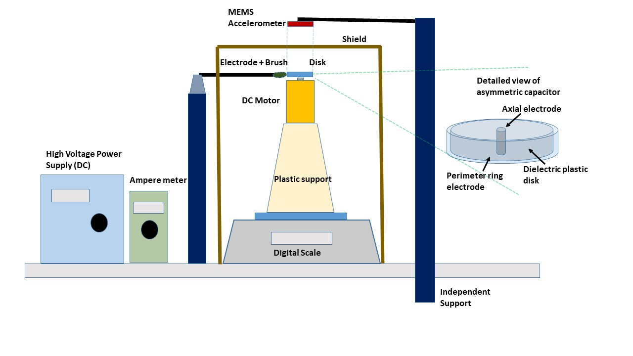
As seen in that figure, the main part of the rotor is composed by a disc made of acrylic (see it in the detail at right), with metallic external border and a metallic ring in its central axis. The disc has diameter 0.04m, radius of its central ring 0.002 m, thickness 0.0025 m and mass approximately equal to 4 g. The perimeter of the disc is enclosed by an aluminum tape. The layer of aluminum measures 35m and it is covered by an external insulated layer with 60m. The internal metallic central ring is mechanically coupled to the metallic axis of a small DC engine (motor) responsible by the rotation of the entire set. The acrylic disc involved in the external border by a metallic ring and in the internal border by a metallic axis of the motor constitutes an asymmetric capacitor with symmetry axis placed in the vertical direction. It is rotated by the electric DC motor placed on a plastic cone, which in turn is placed on the scale tray, so that the disc was away from it, at a 22 cm distance, avoiding in this way any significant electrostatic interaction. The DC electric motor has a cylindrical plastic casing made by PVC film layers for electrical insulation and the scale tray that supports the motor-disk assembly has layers of EVA to damp the mechanical vibrations of the motor and for electrostatic insulation of the scale. The feeding wires of the motor and the electric connection of the dielectric disc axis are doubly insulated, placed apart and linked to supports to significantly decrease the electrostatic interaction among them.
The Figure 1 shows the assembly established in the experiments, including the wires, the battery, the switch key and the digital scale model BEL Mark 303, used to measure variations of weight of the order of 1 mgf of the disc-motor-support assembly, with weight approximately equal to 140 gf.
The source of variable DC high tension was used to feed the dielectric disc by means of two brushes which are electrically connected to the axis and the external ring, each of them with different polarity. An accelerometer model Vectornav VN-100S Rugged was placed with its sensor Z vertically aligned with the symmetry axis 31 cm above it and supported by an independent support to avoid mechanical vibrations of the engine. The accelerometer was connected to the USB output of the computer by means of an insulated and armored wire. The computer executed a software of the accelerometer to register the reading of acceleration. Further a support was placed between the accelerometer and the disc to rule out to the maximum the possibility of wind, electrostatic interaction or acoustical noises. In other words, we take into account in the assembly all procedures to reduce or eliminate the electrostatic acoustic and mechanic interactions on the disc, the digital scale, the accelerometer, high tension source, feeding wires and external environment.
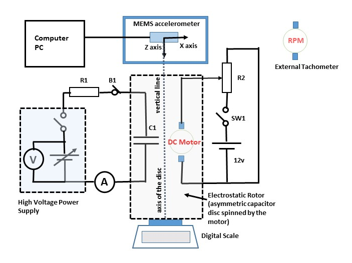
The Figure 2 shows a schematic draw of the electric circuit of the assembly or the electric diagram of the interconnection of the elements used in the experimental setup. Note that the DC electric motor of high rotation has its angular velocity adjusted by the rheostat R2 and its feeding provided by the 12 V battery, beside its activation to be made by the SW1 key. One can also observe that the disc (asymmetric capacitor C1) is fed by the high tension source which has a voltage adjust, an activation key and an internal volt meter through the brush B1 and the resistor R1 in the circuit. The latter corresponds to the insulating layer made of aluminum tape which constitutes the external ring of the disc. The charge current and leakage is controlled by the ampere meter linked in series with C1.
In order to control the magnitude of the angular velocity of the dielectric disc was used an external digital tachometer Hikari model HDT-228 (with photo sensor and laser emitter), as detailed at the right top in the Figure 2.
It is relevant to report that all the experimental measurements to detect auto-induction or anomalous forces on the own rotor were made by using the digital scale and all the measurements involving forces induced at a distance were made by means of the accelerometer.
In the following, we describe our main experimental measurements made with such an experimental assembly.
II.2 Measurements of forces
We first made some measurements of weight variation or anomalous forces for different voltages applied on the device. During the execution of the experiments one realized that it was needed the application of higher values of tension to obtain weight variations overcoming all the noises or interferences, so that the effect was perceptible. Then, higher magnitudes of tension were applied, as shown in Table 1. Table 1 shows three measurements of weight variation, by comparing with previous values of that during the application of high voltage in the dielectric disc in clockwise rotation at an angular velocity of 20000 rpm. We made three measurements to each level of voltage, from 15300 V to 18300 V, which indicated that the weight loss of the disc is proportional to the magnitude of the applied voltage.
For all the measurements shown in Table 1, the experimental setup was the same in which the brush did the contact with a 5 arc of the external ring of the dielectric disc whose external layer was insulated. Hence, only a small fraction (5/360) of the dielectric dipoles of the disc were effectively polarized. Therefore, we made an additional cover of the outer ring of the disc with aluminum foil. In this way, the loads were distributed throughout their external perimeter in the subsequent tests, thus optimizing the system so that all the dipoles inside the disk volume could be polarized.
| Voltage | Test 1(g) Max, | LC(A) | Test 2(g) Max, | LC(A) | Test 3(g) Max, | LC(A) | |
|---|---|---|---|---|---|---|---|
| (V) | (g) | Min & Diff. | Max, Min | Min & Diff. | Max, Min | Min & Diff. | Max, Min |
| 15300 | - | 142.031 | 5.3 | 142.062 | 4.7 | 142.064 | 4.4 |
| - | 142.023 | 3.0 | 142.027 | 3.0 | 141.985 | 3.0 | |
| - | 0.041 | 0.008 | - | 0.035 | - | 0.079 | - |
| 16300 | - | 142.151 | 5.2 | 142.067 | 5.5 | 142.076 | 6.6 |
| - | 142.060 | 3.7 | 142.051 | 3.6 | 142.021 | 3.5 | |
| - | 0.054 | 0.091 | - | 0.016 | - | 0.055 | - |
| 17300 | - | 142.200 | 7.1 | 142.184 | 6.8 | 142.166 | 6.3 |
| - | 142.095 | 4.5 | 142.108 | 4.2 | 142.123 | 4.5 | |
| - | 0.075 | 0.105 | - | 0.076 | - | 0.043 | - |
| 18300 | - | 142.351 | 8.4 | 142.312 | 8.5 | 142.291 | 7.9 |
| - | 142.252 | 5.2 | 142.177 | 5.5 | 142.184 | 5.5 | |
| - | 0.114 | 0.099 | - | 0.135 | - | 0.107 | - |
This led to an increase in the magnitude of the measured weight loss, which reached 1.2 g, that is, more than 1/4 of the disc weight. In such measurement, the measured average current (116.9 A) had a magnitude much greater than that of the currents obtained from the measurements indicated in Table 1 (from 3 A to 8.5 A). Table 6 shows the parameters for this measurement.
II.3 Tests of Symmetry
Experiments with a magnetic rotor indicated an asymmetry in the loss of weight of the device when it rotated in clockwise direction, but no significant loss in the opposite direction. The explanation for that asymmetry can be well understood in our previous work, in a qualitative way, in the framework of GQE Elio2019 .
In order to answer if the same novel effect occurs in a dielectric disc, we performed three batteries of experimental tests at clockwise rotation and also three of them at counterclockwise one. Each battery was made with six different values of DC voltage, from 10550 V to 15500 V, keeping the same angular velocity in all the configurations (around 19000 rpm to 22000 rpm). The experimental tests had the following procedure: in a first step, we measure the first variation of weight by the digital scale after the activation of the high voltage, that is, the source supply was turned on. Tables 2 and 3 shows the values of weight immediately after its activation and the values of weight which stabilized after the activation in all of thirty six tests realized. It is notable that there was weight reduction for all the measurements in clockwise rotation of the dielectric disc, as one can realize in the experimental data given in Table 2; however, in the counterclockwise rotation there was both increasing and decreasing of weight, that is, the behavior was undefined and besides the weight variation presented one order of magnitude lower than those in opposite direction, as one can realize in the experimental data given in Table 3. In other words, the asymmetry was clear also in the case of dielectric rotor here conceived.
| Voltage (V) | Leakage Current (A) & Average (g) | Test 1(g) Max Min Diff. | Test 2(g) Max Min Diff. | Test 3(g) Max Min Diff. |
|---|---|---|---|---|
| 10500 | 0.4 | 126.322 | 126.278 | 126.354 |
| - | 126.201 | 126.206 | 126.236 | |
| -0.10367 | -0.121 | -0.072 | -0.118 | |
| 11500 | 0.6 | 126.339 | 126.201 | 126.174 |
| - | 126.116 | 126.134 | 126.096 | |
| -0.12267 | -0.223 | -0.067 | -0.078 | |
| 12500 | 0.7 | 126.008 | 126.191 | 126.246 |
| - | 125.067 | 126.093 | 126.188 | |
| -0.36567 | -0.941 | -0.098 | -0.058 | |
| 13500 | 0.7 | 126.389 | 126.465 | 126.435 |
| - | 126.165 | 126.197 | 126.13 | |
| -0.26567 | -0.224 | -0.268 | -0.305 | |
| 14500 | 1.1 | 126.553 | 126.56 | 126.534 |
| - | 126.298 | 126.383 | 126.506 | |
| -0.1533 | -0.255 | -0.177 | -0.028 | |
| 15500 | 1.4 | 126.699 | 126.623 | 126.644 |
| - | 126.497 | 126.567 | 126.542 | |
| -0.12 | -0.202 | -0.056 | -0.102 |
| Voltage (V) | Leakage current (A) & Average (g) | Test 1(g) Max Min Diff. | Test 2(g) Max Min Diff. | Test 3(g) Max Min Diff. |
|---|---|---|---|---|
| 10500 | 0.4 | 117.007 | 117.288 | 117.521 |
| - | 117.28 | 117.575 | 117.62 | |
| 0.21967 | 0.273 | 0.287 | 0.099 | |
| 11500 | 0.6 | 118.621 | 118.966 | 118.29 |
| - | 118.798 | 119.204 | 118.547 | |
| 0.224 | 0.177 | 0.238 | 0.257 | |
| 12500 | 0.9 | 119.99 | 120.065 | 120.045 |
| - | 119.965 | 120.021 | 120.195 | |
| 0.027 | -0.025 | -0.044 | 0.15 | |
| 13500 | 1.0 | 120.357 | 120.432 | 120.374 |
| - | 120.37 | 120.398 | 120.381 | |
| -0.00467 | 0.013 | -0.034 | 0.007 | |
| 14500 | 1.3 | 120.639 | 120.619 | 120.763 |
| - | 120.606 | 120.71 | 120.793 | |
| 0.02933 | -0.033 | 0.091 | 0.03 | |
| 15500 | 2.1 | 120.932 | 120.955 | 120.989 |
| - | 120.896 | 120.909 | 120.905 | |
| -0.05533 | -0.036 | -0.046 | -0.084 |
II.4 Dependence on the Angular Velocity
Other sequence of measurements in our experimental work was also implemented to the case of different angular velocities. In order to verify if the dielectric disc could present a weight variation which changed as a function of the angular velocity, we performed some different measurements of the weight reduction as a function of the high tension when it is activated and deactivated to all the eight different levels of angular velocity, as shown in Table 4. The angular velocity was adjusted as a function of the DC tension feeding the motor and it was measured with the external tachometer. There was a certain variation of angular velocity even for the same values of DC tension. The minimum and maximum values were also indicated in Table 4. Analyzing the correlation between the weight reduction and the average angular velocity, we did not detect any correspondence or correlation between the weight reduction and the angular velocity for a high and constant value of tension applied of 12800 V.
| DC motor | Minimum rotation | Maximum rotation | Average | |
| voltage (V) | (rpm) | (rpm) | (rpm) | (g) |
| 3.0 | 7078 | 13266 | 10172 | -0.0495 |
| 4.8 | 1334 | 22097 | 8947.5 | 0.24425 |
| 5.8 | 5294 | 21872 | 11479.75 | -0.15525 |
| 6.2 | 1296 | 13740 | 7518 | 0.05525 |
| 6.6 | 271.6 | 36902 | 16144.2 | -0.0875 |
| 7.2 | 19035 | 19369 | 19202 | -0.338 |
| 9 | 14100 | 24323 | 19211.5 | -0.03925 |
| 10.8 | 4234 | 37461 | 22994.75 | -0.04525 |
II.5 Experiments of Induction at a Distance
Thirty measurements were also made to check if the dielectric disk could induce forces at a distance in such a way that gravitational acceleration measurements undergone changes detectable by an accelerometer positioned with its z sensor 31 cm above the axis of symmetry of the disk. Such changes in the gravitational acceleration cannot be explained by trivial local interactions such as electrostatic, acoustic or mechanical (wind) in view of the shield that was interposed between the disc and the accelerometer.
Table 5 shows a summary of the 30 measurements made, 6 measurements for each of the five lines shown, each showing the direction of rotation of the disk and if the body of the accelerometer was aligned within the vertical projection of the circular area of the disk or was misaligned or outside the same projection.
Each of the 30 measurements corresponds to 80 samples obtained by the accelerometer in a period of 2 s immediately prior to the high voltage activation period and 2 s immediately after the same activation.
Table 5 shows that the dielectric disc induced a force whose vector points downwards on the activation of high voltage (12800 V) and clockwise rotation of 20000 rpm in such a way that the gravitational acceleration measured by the accelerometer z-sensor has decreased. Such a decrease was more than four times smaller than when the accelerometer body was misaligned with respect to the dielectric disk, which denotes that the distance induction has a collimation feature or a dependence on the geometry.
| - | Voltage ”off” | Voltage ”off” | Voltage ”on” | Voltage ”on” | Difference |
|---|---|---|---|---|---|
| Direction of rotation | Average | Da | Average | Da | Average |
| & Alignment | a(m/s2) | (m/s2) | a(m/s2) | (m/s2) | a(m/s2) |
| CW - Aligned | -9.1604 | 0.0623 | -9.1417 | 0.0563 | 0.0187 |
| CCW - Aligned | -9.1454 | 0.0423 | -9.1545 | 0.0393 | -0.0091 |
| CW - Misaligned | -9.1407 | 0.046 | -9.1362 | 0.054 | 0.0045 |
| CCW - Misaligned | -9.1427 | 0.039 | -9.1445 | 0.0537 | -0.0018 |
| No rotation - Aligned | -9.1366 | 0.048 | -9.1307 | 0.0363 | 0.0059 |
Both effects, that is, remote induction and self-induction of forces (where the forces are measured as a variation in the weight of the dielectric disk itself) in the experiments, are not well explained considering those trivial interactions such as electrostatic, acoustic, or mechanical, so they can be ruled out according to the procedures, protections and insulation that have been carried out. Such effects concerning to the generation of anomalous forces or weight reduction have been observed in other different physical systems, as in the case of weight reduction in capacitors Musha and in case of Podkletnov experiments involving superconductors Podkletnov ; Solomon ; McCulloch and some authors have proposed some possible explanations for that Solomon ; Zhu . For instance, in Ref. Zhu it has been shown the conditions for the existence for the interaction between the electromagnetic and gravitational fields, so that the variation of gravitational acceleration could be measured.
So, we propose a possible theoretical explanation to the phenomenon. Next, we propose a theoretical model that can explain both qualitative and quantitative experimental results.
III Theoretical Model
The theoretical model is based on the idea that the myriad of internal electric dipoles in the acrylic dielectric disc which undergoes a polarization of intense radial electric field between the external ring and the axis really affects the physical quantities of the system in macroscopic scale. In this condition, if the dielectric disc is under high rotation then the electric dipoles also undergo a precession effect Talman , so that either they oscillate around a vector pointing downwards if the rotation of the disc is clockwise (that is, the angular momentum of the disc points downwards in the vertical direction) or oscillates around a vector pointing upwards if the rotation of the disc is counterclockwise (or if the angular momentum of the disc aligned to the vertical direction points upwards).
The model also considers the existence of generalized quantum entanglement (GQE) as a conjecture Elio2017a between the myriad of electric dipoles collectively synchronized in precession and the environment around the disc. In general, that non-local interaction is very weak, but in some special conditions such an interaction can become more intense and be perceptible.
When the electric dipoles precess downwards, due to the non-local interaction with the planet below them, they undergo a reaction force upwards so that there is a decreasing in the weight of the disc. That same process was verified in the case of magnetic dipoles in magnetic rotors, according our previous work Elio2019 . When the electric dipoles precess upwards, due to the non-local interaction with the atmosphere and the outer space above them, they undergo a reaction force downwards, but it is very weak because the density of the matter above the device is very small when compared with the density of the Earth. So, it is clear that there exists an asymmetry in the framework of GQE as an explanation to the anomalous forces arising in the device. In other words, the disc looses weight in clockwise rotation, but it does not effectively gain weight in counterclockwise rotation, exactly as occurs in the case of the gyroscope Elio2019 . Such an asymmetry was in fact detected in our experiments whose data are presented in Tables 2 and 3.
Based on the model here proposed, it is possible to calculate the magnitude of the reaction force that the electric dipoles in precession can induce in the disc in clockwise rotation when subjected to a static radial electric field. In reality, each electric dipole in precession transfers a non-local force in the direction of the precession, which is the direction where points out the vector angular momentum of the disc. Hence, in first place, we must calculate the torque of the individual electric dipole , whose magnitude of dipole momentum is about 1.6 x 10⁻²⁹ Cm, according to Ref. Housecroft ; Podesta ; Tro . That magnitude is consistent with the electronic polarization of the dielectric, which is dominant in the device due to the lower value of the dielectric constant of the disc: 3.22 and the application of the static radial electric field which is not variable in time.
The torque is easily calculated by
| (1) |
in which is the magnitude of the electric field vector which polarizes all the electric dipoles constituting the material of the dielectric. The electric field can be calculated according some parameters as the radial distance between the bigger electrode (ring involving the perimeter of the dielectric disc) and the smaller one (metallic axis in the center of the dielectric disc), the difference of electric potential between the electrodes (voltage applied) and the factor of field concentration , according to Ref. Fazi , if we take into account that the system represents an asymmetric capacitor with electrodes of different dimensions. So, we can write the magnitude of the electric field as:
| (2) |
in which is the difference between the values of radius of the external ring and the axis and is the gradient of the electric field, which can be calculated by
| (3) |
so that Eq. (3) represents the ratio involving the radii of the electrodes.
In this way, it is possible to calculate the magnitude of the torque undergone by each dielectric dipole, by considering , that is, the direction of the axes where the electric dipoles precess around is perpendicular to the direction of the radial electric field in the bulk of the disc. As the magnitude of the torque is the contribution of all individual torques of the electric dipoles , we can write as average torque = , in which is the number of dipoles. The next step is to calculate the quantity of electric dipoles of the dielectric disc. For that, it is needed to calculate the polarization of the dielectric Woan ; Mossotti ; Clausius , according to:
| (4) |
in which is the dielectric constant of the material (acrylic) PPD , is the dielectric constant of the vaccum, is the effective electric field and is a proportionality constant Indulgar which has value 3 to isotropic dielectric materials, but we here consider it in our model as = 1. This value is considered different than 3 due to the polarizability anisotropy of the polymer PMMA (acrylic) used in the dielectric disk Pol1 ; Pol2 .
Hence, it is possible to obtain the average total torque as and we can also calculate the value of the average force by
| (7) |
in which is the radius of the dielectric disc. Such a force of reaction raises due to the precession of the dielectric dipoles originated from the electric field applied and the angular momentum of the disc. Such an effect would not be possible if it was not intermediated with the exterior (environment) by considering the preexistent generalized quantum entanglements.
IV Results
Our calculations indicate that there is a good agreement with the experimental data obtained from literature for most rotation frequencies measured. The theoretical model presented in section III is consistent with the experimental results given in Table 6 of section II.
Table 6 shows the theoretical predictions of the magnitude reaction force according to the experimental parameters used in the calculations demonstrated up to this point and also the experimental measurements of that force, that is, the decreasing of the disc weight in clockwise rotation also indicated in Table 1.
| Parameter | 1st Runs | 2nd Runs | 3th Runs | 4th Runs | 5th Runs |
|---|---|---|---|---|---|
| Energized portion of the ring | 0.01389 | 0.01389 | 0.01389 | 0.01389 | 1.0 |
| Electric dipole(Cm) | 1.6x10⁻²⁹ | 1.6x10⁻²⁹ | 1.6x10⁻²⁹ | 1.6x10⁻²⁹ | 1.6x10⁻²⁹ |
| Effective voltage (V) | 15300 | 16300 | 17300 | 18300 | 8378.88 |
| 3.22 | 3.22 | 3.22 | 3.22 | 3.22 | |
| (F/m) | 8.85x10⁻¹² | 8.85x10⁻¹² | 8.85x10⁻¹² | 8.85x10⁻¹² | 8.85x10⁻¹² |
| E field (MV/m) | 8.5 | 9.056 | 9.61 | 10.167 | 4.655 |
| Polarization(Cm) | 1.38x10⁻¹² | 1.47x10⁻¹² | 1.56x10⁻¹² | 1.65x10⁻¹² | 5.45x10⁻¹¹ |
| Big electrode(m) | 0.02 | 0.02 | 0.02 | 0.02 | 0.02 |
| Small electrode (m) | 0.002 | 0.002 | 0.002 | 0.002 | 0.002 |
| Thickness of dielectric disk(m) | 0.0025 | 0.0025 | 0.0025 | 0.0025 | 0.0025 |
| Dielectric vol.(m3) | 3.110x10⁻⁶ | 3.110x10⁻⁶ | 3.110x10⁻⁶ | 3.110x10⁻⁶ | 3.110x10⁻⁶ |
| Gradient of field | 10 | 10 | 10 | 10 | 10 |
| Dipoles number | 8.638x10¹⁶ | 9.202x10¹⁶ | 9.767x10¹⁶ | 1.033x10¹⁷ | 3.41x10¹⁸ |
| Torque of each dipole (Nm) | 1.36x10⁻²² | 1.45x10⁻²² | 1.54x10⁻²² | 1.63x10⁻²² | 7.45x10⁻²³ |
| Torque (Nm) | 1.18x10⁻⁵ | 1.33x10⁻⁵ | 1.50x10⁻⁵ | 1.68x10⁻⁵ | 2.54x10⁻⁴ |
| Theoretical Force (gf) | 0.0599 | 0.067998 | 0.0766 | 0.0857 | 1.2937 |
| Average exp. force (gf) | 0.041 | 0.054 | 0.075 | 0.114 | 1.2 |
| Minimum exp. force (gf) | 0.008 | 0.016 | 0.043 | 0.099 | - |
| Maximum exp. force (gf) | 0.079 | 0.091 | 0.105 | 0.135 | - |
The parameters of the data sets from 1 to 4 are equal, with exception of the voltages applied (from 15300 V to 18300 V) by the contact brush (electrode) in 5 of the arc of the ring, so that only a part of it (5/360) was energized. So, only a fraction of the volume of the dielectric disc had its internal electric dipoles polarized. The theoretical values of the magnitude of the force are consistent with the experimental results shown in all those data sets (1 to 4) if we consider that they are within the interval between the maximum and minimum measurements and they are also very close to the average values which were measured.
In the data set 5, the parameters were equal to the earlier, but with an important exception, that is, all the perimeter of the ring was energized so that all the dielectric dipoles of the entire volume of the dielectric disc have been polarized.
The result of that experimental procedure was a very high value of the magnitude of the force calculated in our model: = 1.29367 gf. That value is very close to the value measured in our experiments: 1.2 gf. Such a loss of weight represents about 1/4 of the total weight of the dielectric disc ( 4 gf).
It is important to emphasize that in all the experimental rounds shown in Table 6 there was loss of weight consistent with the same magnitude of angular velocity ( = 20000 rpm) and the direction of disc rotation (clockwise).
In summary, the Tables 2 and 3 shows the weight variation with relation to the direction of rotation (right or left) to different voltages applied to the system, that is, from 10500 V to 15500 V. Such results allow us to conclude the existence of an actual asymmetry in the effect, according to the theory here described. Besides, for all voltages applied to the device there was weight reduction when the rotation was clockwise, in opposition to the case of counterclockwise rotation, in which no reduction was in fact detected in the accuracy considered (at least one order of magnitude lower than the positive case).
The measurements performed in the experiments whose values can be seen in Tables 2 and 1 were more conclusive than the ones in Table 3 because the voltages applied were higher so that the residual variations on the background as noises and mechanical variations of the rotor were overcome in the former case. Despite of that, it is doubtless the asymmetry observed in Tables 2 and 3.
Table 4 shows measurements of force performed in clockwise rotation to different values of angular velocity by means of the change of electric tension feeding the engine which imposes the rotation of the electric disc. It is worth to report that the voltage applied on the ring was the same in all the measurements, e.g., 11000 V.
In most part of the measurements, there was a loss of weight in the right rotation, but there was not observation of increase in the variation of weight according to the increase of the angular velocity. In the model proposed in this paper and according to the theory of gyroscopes Jan , the precession velocity of the electric dipoles depends on the torque on them applied, when subjected to a radial electric field , and also depends on the angular momentum which are subjected to, due to the angular velocity of the dielectric disc, so that the angle of precession can vary in time according to:
| (8) |
Note that the torque which each electric dipole undergoes with the application of the electric field is responsible for the magnitude of the force transferred to the exterior via non-local interactions and the direction of the force varies as a function of the precession angle and the latter depends on the angular momentum of each electric dipole due to the rotation of the dielectric disc. Therefore we conclude that the reaction force (or the weight reduction) does not depend on the angular velocity, confirming the experimental results shown in Table 4. Such a new result does not occur in the case of magnetic rotors, as seen in our previous work Elio2019 because the radial magnetic field increased in magnitude when the angular velocity of the rotor also increased. In the present case, the radial electric field remained unchanged in magnitude, independently the variation of the angular velocity.
The theoretical model proposed in this paper indicates that the electric dipoles interact with the exterior environment (or, in other words, with their particles) due to the existence of the quantum entanglement property. When the particles undergo the torque of the electric field, they transfer forces to the external environment which depend on the direction of precession. Such a direction is either downwards when the disc rotation occurs in the clockwise direction or upwards when the rotation occurs in the counterclockwise direction. Such a phenomenon was experimentally verified, as one can be seen in Table 5.
We detected a collimated field of forces by means of an
accelerometer placed above the dielectric disc by tens
of centimeters. The accelerometer z-sensor was also aligned with
the symmetry axis of the disc and then we detected the
decreasing of the gravity acceleration (or, in other
words, its body undergoes a force downwards) when the
disc rotated at right. Analogously, we detected an
increase in the gravity acceleration (the body of the
accelerometer undergoes a force upwards) when the disc
rotated in the opposite direction. Such a behavior occurred
even with the lack of alignment of the z-sensor in
relation to the symmetry axis of the disc. In fact, there
was a dislocation of the accelerometer in the Y-axis
as to stay out the projection of the circular area of
the disc in the z-axis. However, the variation of
the gravitational acceleration measured was much smaller, so
that we really verified that the force induced by
the disc in rotation and under high tension presented
as a feature the dependence on the collimation. Such
a property or geometry of forces induced depends on
the precession of the electric dipoles and deserves
a more profound investigation in future works.
V Conclusion
In this paper we performed some experiments of force measurements in a device analogue to the gyroscope or magnetic rotor. We investigate three main novel features of our dielectric rotor: the existence of anomalous forces or weight reduction of the device, the asymmetry in the magnitude of those forces (significant higher forces only appeared for right rotations) and the possibility of induction of forces at a distance. We conclude that the three features do occur in our experimental dielectric rotor for high values of voltage applied to that device and high angular velocities. No dependence on the angular velocity was observed, an unique difference in relation to the analogue magnetic rotor previously reported in Ref. Hay1 . We also propose an empirical theoretical model to explain the effect which was based on the conjecture of generalized quantum entanglement which provides us an expression indicating that the collective precession of the electric dipoles constituting the dielectric rotor can accurately describe the experimental data in all the cases. Hence we conclude that our theoretical model is consistent with the experimental results. It is notable to realize that in the best result we obtained approximately a 1.2 gf weight reduction of the device, corresponding to impressive 25% of the device weight.
References
- (1) J. M. Bruckner, GPS analytic redundancy for gyroscope failure detection, US Patent US6266582B1, 2017.
- (2) W. Gao, Q. Nie, G. Zai, H. Jia, Gyroscope Drift Estimation in Tightly-coupled INS/GPS Navigation System. In: 2nd IEEE Conference on Industrial Electronics and Applications, 23-25 May, 2007.
- (3) K. Najafi, J. Chae, H. Kulah, G. He, Micromachined silicon accelerometers and gyroscopes, In: Proceedings 2003 IEEE/RSJ International Conference on Intelligent Robots and Systems, 2003.
- (4) A. Allan, Basic Sensors in iOS, Sebastopol, CA: O’Reilly Media Inc.; 2011.
- (5) D. Ionescu, B. Ionescu, C. Gadea, S. Islam, Multimodal control of virtual game environments through gestures and physical controllers. In: 2011 IEEE International Conference on Virtual Environments, Human-Computer Interfaces and Measurement Systems Proceedings, Ottawa, Canada, 2011.
- (6) N. Venkateswaran, M. S. Siva, P. S. Goel, Analytical redundancy based fault detection of gyroscopes in spacecraft applications, Acta Astron., 50(9), 535-545 (2002).
- (7) J. Söderkvist, Micromachined Gyroscopes, Sensors and Actuators A: Physical 1994; 43(1-3): 65-71.
- (8) J. C. Fang, J. Qin, Advances in Atomic Gyroscopes: A View from Inertial Navigation Applications, Sensors 2012; 12(5): 6331-6346.
- (9) C. Acar, A. R. Schofield, A. A. Trusov, L. E. Costlow, A. M. Shkel, Environmentally Robust MEMS Vibratory Gyroscopes for Automotive Applications, IEEE Sensors Journal 2009; 9(12): 1895-1906, Dec. 2009.
- (10) X. Roser, M. Sghedoni, Control Moment Gyroscopes (CMG’s) and their Application in Future Scientific Missions. Spacecraft Guidance, Navigation and Control Systems, Proceedings of the 3rd ESA International Conference ESTEC 1997; Noordwijk, the Netherlands, Edited by Brigitte Kaldeich-Schuermann, ESA SP-381, European Space Agency, 523-528.
- (11) R. Antonello, R. Oboe, MEMS Gyroscopes for Consumer and Industrial Applications. In Microsensors 2011; Edited by Prof. Igor Minin, InTech. Available from: http://www.intechopen.com/books/microsensors/mems-gyroscopes-for-consumers-and-industrial-applications
- (12) H. Hayasaka, S. Takeuchi, Anomalous Weight Reduction on a Gyroscope’s Right Rotation around the Vertical Axis on the Earth, Phys. Rev. Lett. 1989; 63(25): 2701-2704.
- (13) H. Hayasaka, H. Tanaka, T. Hashida, T. Chubachi, T. Sugiyama, Possibility for the existence of anti-gravity: evidence from a free-fall experiment using a spinning gyro, Speculations in Sci. and Tech. 1997; 20, 173-181.
- (14) J. E. Faller, W. J. Hollander, P. G. Nelson, and M. P. McHugh, Gyroscope-weighing experiment with a null result, Phys. Rev. Lett. 1990; 64, 825-826.
- (15) T. J. Quinn, A. Picard, The mass of spinning rotors: no dependence on speed or sense of rotation, Nature 1990; 343, 732-735.
- (16) J. M. Nitschke, P. A. Wilmarth, Null result for the weight change of a spinning gyroscope, Phys. Rev. Lett. 1990; 64, 2115-2116.
- (17) E. B. Porcelli and Victo S. Filho, On the Possible Anomaly of Asymmetric Weight Reduction of Gyroscopes under Rotation. Trends Journal of Sciences Research 2019; 4(1), 29-38.
- (18) E. B. Porcelli and Victo S. Filho, On the Anomalous Weight Losses in High-Voltage Symmetrical Capacitors. arXiv:1502.06915, 2015.
- (19) E. B. Porcelli and Victo S. Filho, On the Anomalous Forces in High-Voltage Symmetrical Capacitors. Phys. Essays 2016; 29, 2-9.
- (20) E. B. Porcelli and Victo S. Filho, Characterisation of Anomalous Asymmetric High-Voltage Capacitors. IET Sci., Meas. & Tech., 2016, 10(4), 383-388.
- (21) E. B. Porcelli and Victo S. Filho, Experimental Verification of Anomalous Forces on Shielded Symmetrical Capacitors. Appl. Phys. Res. 2020; 12(2), 33-41.
- (22) E. B. Porcelli and Victo S. Filho, Explaining anomalous forces in dielectric EM drives. IET Science, Measurement & Technology, 12(8), 977-982 (2018).
- (23) E. B. Porcelli and Victo S. Filho, Anomalous Effects from Dipole-Environment Quantum Entanglement. Int. J. Adv. Eng. Res. Sci., 4(1), 131-144 (2017).
- (24) E. B. Porcelli and Victo S. Filho, Theoretical Study of Anomalous Forces Externally Induced by Superconductors. Nat. Sci. J., 9(9), 293-305 (2017).
- (25) E. B. Porcelli and Victo S. Filho, Analysis of Possible Nonlocal Forces in Superconducting Materials. J. Power Eng. En., 6(1) 85-95 (2018).
- (26) E. B. Porcelli and Victo S. Filho, Induction of Forces at Distance Performed by Semiconductor Laser Diodes. Amer. J. Eng. Res., 6(5), 35-48 (2017).
- (27) E. B. Porcelli and Victo S. Filho, Induction of Forces at Distance Performed by Piezoelectric Materials, J. Power Eng. En., 6(1), 33-50 (2018).
- (28) E. B. Porcelli and Victo S. Filho, Analysis of Possible Nonlocal Effects in Laser Beams Generated by Piezoelectric Ceramic, J. Power Eng. En., 2018, 6(2), 20-32 (2018).
- (29) E. B. Porcelli and Victo S. Filho, Characterization of Anomalous Nonlocal Forces Generated by Piezoelectric Devices, Journal of Multidisciplinary Engineering Science and Technology, 2020, 7(6), 12113-12120 (2020).
- (30) E. B. Porcelli and Victo S. Filho, On the Anomalous Forces in Microwave Cavity-Magnetron Systems, The Journal of Engineering, 2018(10), 7279-7286 (2019).
- (31) T. Musha, Explanation of Dynamical Biefeld-Brown Effect from the Standpoint of ZPF Field, Journal of the British Interplanetary Society, 61, 379-384 (2008).
- (32) E. Podkletnov, G. Modanese, Investigation of High Voltage Discharges in Low Pressure Gases Through Large Ceramic Superconducting Electrodes, Journal of Low Temperature, 132, 239-259 (2003).
- (33) B. T. Solomon. An Introduction to Gravity Modification: A Guide to Using Laithwaite’s and Podkletnov’s Experiments and the Physics of Forces for Empirical Results, Universal Publishers, 2012.
- (34) M. E. McCulloch, Can the Podkletnov effect be explained by quantised inertia?, Physics Procedia, 20, 134-139 (2011).
- (35) Y. Zhu, Gravitational-magnetic-electric field interaction, Results in Physics, 10, 794-798 (2018).
- (36) R. Talman, The Electric Dipole Moment Challenge, San Rafael, CA, USA: Morgan and Claypool Publishers, 2017.
- (37) C. E. Housecroft, A. G. Sharpe, Inorganic Chemistry. 3rd Ed., Harlow: Pearson Education, 44-46 (2008).
- (38) M. Podesta, Understanding the Properties of Matter, 2nd Ed., Nat. Phys. Lab., London, UK: Taylor & Francis, 2002.
- (39) N. J. Tro, Chemistry: A Molecular Approach, Upper Saddle River: Pearson Education, 379-386, 2008.
- (40) T. B. Bahder, C. Fazi, Force on an Asymmetric Capacitor. Electrogravitics II, Integrity Research Institute, Washington, 2005, 28-59.
- (41) G. Woan, The Cambridge Handbook of Physics Formulas, Cambridge University Press, 2000.
- (42) O. F. Mossotti, Discussione analitica sull’influenza che l’azione di un mezzo dielettrico ha sulla distribuzione dell’elettricità alla superficie di più corpi elettrici disseminati in esso, Memorie di Mathematica e di Fisica della Società Italiana della Scienza Residente in Modena, 24, 49-74 (1850).
- (43) R. Clausius, Abhandlungen über die mechanische Wärmetheorie. Friedrich Vieweg und Sohn, Braunschweig, 2, 143 (1867).
-
(44)
Polymer Properties Database. Accessed Sept. 2020. URL: http://polymerdatabase.com/polymer%20physics/
Epsilon%20Table.html - (45) C. S. Indulgar, S. Thiruvengadan, An Introduction to Electrical Engineering Materials. New Delhi, India: S.Chand & Company PVT. LTD., Ran Nagar, 1967.
- (46) B. E. Read, Dynamic birefrigene of poly (methyl methacrilase). Journal of Polymer Science Part C: Polymer Symposia, 16(4), 1887-1902 (1967).
- (47) J. Mark, K. Ngai, W. Graessley, L. Mandelkern, E. Samulski, J. Koenig, G. Wignall, Physical Properties of Polymers, Cambridge University Press, 3 Edition, 2004.
- (48) J. Awrejcewicz, Z. Koruba, Theory of Gyroscopes, In Classical Mechanics, New York, NY, USA: Springer, 2012, 125-147.