Enabling High-Capacity, Latency-Tolerant, and Highly-Concurrent GPU Register Files via Software/Hardware Cooperation
Abstract.
Graphics Processing Units (GPUs) employ large register files to accommodate all active threads and accelerate context switching. Unfortunately, register files are a scalability bottleneck for future GPUs due to long access latency, high power consumption, and large silicon area provisioning. Prior work proposes hierarchical register file to reduce the register file power consumption by caching registers in a smaller register file cache. Unfortunately, this approach does not improve register access latency due to the low hit rate in the register file cache.
In this paper, we propose the Latency-Tolerant Register File (LTRF) architecture to achieve low latency in a two-level hierarchical structure while keeping power consumption low. We observe that compile-time interval analysis enables us to divide GPU program execution into intervals with an accurate estimate of a warp’s aggregate register working-set within each interval. The key idea of LTRF is to prefetch the estimated register working-set from the main register file to the register file cache under software control, at the beginning of each interval, and overlap the prefetch latency with the execution of other warps. We observe that register bank conflicts while prefetching the registers could greatly reduce the effectiveness of LTRF. Therefore, we devise a compile-time register renumbering technique to reduce the likelihood of register bank conflicts. Our experimental results show that LTRF enables high-capacity yet long-latency main GPU register files, paving the way for various optimizations. As an example optimization, we implement the main register file with emerging high-density high-latency memory technologies, enabling 8 larger capacity and improving overall GPU performance by 34%.
1. Introduction
Graphics Processing Units (GPUs) are commonly-used accelerators, optimizing silicon organization with dense arithmetic for data-parallel workloads. Modern GPU microarchitecture relies on managing execution resources for a large number of Single-Instruction-Multiple-Data (SIMD) threads to exploit this arithmetic density and overlap the long memory access latency with computation (NVIDIA, 2014a). Unfortunately, the maximum parallelism in GPUs is fundamentally limited by the register file capacity as the register file must accommodate all simultaneously running threads (Gebhart et al., 2011a; Lee et al., 2015; Gebhart et al., 2011b; Wang and Xie, 2015; Mao et al., 2014; Abdel-Majeed et al., 2017; Gebhart et al., 2012).
GPU register files face the difficult challenge of optimizing latency, bandwidth, and power consumption, while having maximal capacity. Prior work proposes increasing the register file capacity in various ways: compression (Lee et al., 2015), virtualization (Jeon et al., 2015; Vijaykumar et al., 2016), or silicon technologies for high-density memory cells (Wang and Xie, 2015; Liu et al., 2015, 2014; Jing et al., 2013b; Jing et al., 2013a; Mao et al., 2014; Li et al., 2013). While such proposals increase capacity without sacrificing power consumption, they typically result in higher register access latencies.
Register file caching (Gebhart et al., 2011a; Gebhart et al., 2011b) is a promising approach to enhancing capacity while lowering power consumption and effective access latency. Unfortunately, existing proposals for register file caching do not achieve high enough hit rates in the register cache due to three key problems. First, the high degree of thread-level parallelism (TLP) in GPUs causes threads to displace each other’s registers in the cache. Second, registers house temporary values that are often renamed, which reduces temporal locality in the cache. Third, because register names are not spatially correlated, there is no spatial locality in a register cache. Due to these reasons, register file caching is ineffective at hiding latency in GPUs (§ 7).
Our goal is to improve the effectiveness of register file caching in GPUs. To this end, we observe that registers can be effectively prefetched into the register cache using compile-time interval analysis to hide the long access latency of the main register file. An interval is a subgraph in a program’s control-flow graph that has a single entry point. Intervals have been widely used by optimizing compilers to identify loops (Hecht, 1977). We use interval analysis and software prefetching to fetch the entire set of required registers of an interval into the register cache and thus avoid the main register file access latency during the execution of the interval.
We propose the Latency-Tolerant Register File (LTRF), a two-level hierarchical register file that employs a low-latency/low-power first-level register file cache backed up by a high-latency/high-capacity second-level main register file. LTRF uses a compiler-driven software mechanism to prefetch a warp’s register working-set into the register cache at the start of an interval. By fetching all registers in the working-set together and overlapping the prefetch latency of one warp with the execution of another, LTRF hides a substantial fraction of the access latency of the main register file during the execution of the interval.
To accelerate register prefetching operations, it is crucial to avoid main register file bank conflicts. As the main register file banks are single ported, the bank conflicts increase the prefetch latency significantly. To resolve the main register file bank conflicts, we also devise a compile-time register renumbering technique on top of LTRF, while preserving the correctness of the program.
By using LTRF, we enable high-capacity yet long-latency main register files, paving the way for various optimizations. As an example optimization, we implement the main register file with high-density emerging memory technologies, e.g., domain wall memory (Venkatesan et al., 2014; Mao et al., 2014; Annunziata et al., 2011; Augustine et al., 2011; Parkin et al., 2008; Sharad et al., 2013; Tavakkol et al., 2018), enabling 8 larger capacity and improving overall GPU performance by 31% while reducing register file power consumption by 46%. In contrast, the state-of-the-art register file caching schemes reduce GPU performance by 14%, on average, if the register file is enlarged by 8, as prior designs do not focus on tolerating the latency of the main register file.
This paper makes the following contributions:
-
•
We show that prior proposals for register file caching do not achieve high enough hit rates to effectively hide the long latencies of large main register files (§ 7).
-
•
We introduce LTRF, a latency-tolerant hierarchical register file design, which enables high-capacity yet long-latency main register files. The key idea is to 1) estimate the register working set of a program’s execution during an interval, using compile-time interval analysis, 2) prefetch the estimated register working-set from the main register file to the register file cache under software control, at the beginning of each interval, and overlap the prefetch latency with the execution of other warps.
-
•
We devise a compile-time register-renumbering technique to mitigate the overhead of register bank conflicts in register prefetching operations.
-
•
Our evaluations show that an optimized version of LTRF, when implemented with an 8 larger yet 6.3 slower main register file, improves overall GPU throughput by 31%, on average (up to 86%). LTRF performance is within 5% of an ideal 8-capacity main register file that has no latency overhead.
2. Background and Motivation
Figure 1 illustrates a conventional GPU register file architecture (Lindholm et al., 2008) in a streaming multiprocessor (SM). To accommodate a large number of active threads, a GPU employs a register file of megabytes in size. For example, GP100 (NVIDIA Pascal) has a register file of 14.3 megabytes in total (NVIDIA, 2016). The register file is heavily banked (16 banks) and it allows concurrent accesses from many threads (up to 512 threads). Each bank stores registers from multiple warps. When the GPU issues an instruction, an operand collector concurrently accesses and gathers data associated with each thread in the issued warp’s instruction through an arbiter and a large and wide crossbar, as shown in Figure 1. The warp scheduler arbitrates among ready warps (i.e., a warp whose operands are collected) and issues the warp’s instruction to the SIMD units.

In this section, we demonstrate the increasing demand for larger register file capacity, analyze shortcomings of prior register caching mechanisms for GPUs, and motivate the case for a design that provides high capacity without significantly increasing power consumption, on-chip die area, or access latency exposed to the GPU core.
2.1. Factors that Limit GPU Performance
When a warp encounters a long-latency memory instruction, the GPU selects another ready warp to be scheduled for execution, in order to prevent the GPU core from stalling. While the applications with high TLP are more likely to contain more ready warps and are able to hide long-latency stalls more effectively, these applications with high TLP demand a large register file in order to realize their maximum TLP. To illustrate the impact of the register file size on an application’s TLP, we recompile 35 workloads in CUDA SDK (Bakhoda et al., 2009), Rodinia (Che et al., 2009), and Parboil (Stratton et al., 2012) benchmark suites with the maxregcount attribute (i.e., the attribute that enables the use of the maximum number of registers for each GPU function, i.e., 64 and 256 for Fermi and Maxwell respectively) enabled in the NVIDIA GPU compiler, nvcc. Doing so enables us to measure the number of registers applications would require if there were no register file size constraints.
Table 1 reports the average and maximum register file capacity needed for our benchmarks to achieve the maximum TLP provided by the two GPU products. This experiment shows that a larger register file would directly translate into a larger number of executing threads, thereby increasing TLP, on average. The table corroborates our intuition that TLP is indeed limited by the number of registers and many applications benefit from compiler optimization when given a larger register file (Magni et al., 2013; Yang et al., 2012; Murthy et al., 2010). The results also show that the recent version of the CUDA compiler used for Maxwell employs more aggressive compiler optimization techniques (e.g., loop unrolling) and as such enhances register usage and TLP compared to Fermi.
| GPU | Average required | Maximum required |
|---|---|---|
| (baseline register file size) | register file size | register file size |
| Fermi (128KB) | 184KB (1.4) | 324KB (2.5) |
| Maxwell (256KB) | 588KB (2.3) | 1504KB (5.9) |
2.2. Register File Scalability
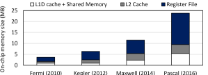
While modern GPUs integrate more execution resources with increases in silicon density and memory bandwidth in each chip generation, the register file accounts for an increasingly larger fraction of on-chip storage, as shown in Figure 2. For NVIDIA Pascal (NVIDIA, 2016), more than 60% of the on-chip storage area, amounting to 14.3 MB is dedicated to the register file. GPU register files face the difficult challenge of optimizing latency, bandwidth, and power consumption, while having maximal capacity (Wang and Xie, 2015; Liu et al., 2015, 2014; Jing et al., 2013b; Jing et al., 2013a; Mao et al., 2014; Li et al., 2013; Gebhart et al., 2011a; Gebhart et al., 2011b; Lee et al., 2015; Samavatian et al., 2015; Hsiao et al., 2014; Abdel-Majeed and Annavaram, 2013; Samavatian et al., 2014; Jeon et al., 2015; Vijaykumar et al., 2016; Vijaykumar et al., 2015). Larger register files are slower, take up more silicon area and consume more power. Increasing concurrency by adding more banks exacerbates complexity and power consumption with the addition of a larger crossbar. Prior work attempts to reduce the power consumption of the register file while keeping the register access latency almost unchanged. As a result, the reduction in the power consumption is limited by the access latency of the register file. In this section, we measure the impact of various register file design parameters and configurations on register file access latency and overall GPU throughput.
| Config. | Cell Technology | #Banks | Bank Size | Network | Cap. | Area | Power | Cap./Area | Cap./Power | Latency |
|---|---|---|---|---|---|---|---|---|---|---|
| #1 | HP SRAM | 1 | 1 | Crossbar | 1 | 1 | 1 | 1 | 1 | 1 |
| #2 | HP SRAM | 1 | 8 | Crossbar | 8 | 8 | 8 | 1 | 1 | 1.25 |
| #3 | HP SRAM | 8 | 1 | F. Butterfly | 8 | 8 | 8 | 1 | 1 | 1.5 |
| #4 | LSTP SRAM | 1 | 8 | Crossbar | 8 | 8 | 3.2 | 1 | 2.5 | 1.6 |
| #5 | LSTP SRAM | 8 | 1 | F. Butterfly | 8 | 8 | 3.2 | 1 | 2.5 | 2.8 |
| #6 | TFET SRAM | 8 | 1 | F. Butterfly | 8 | 8 | 1.05 | 1 | 7.6 | 5.3 |
| #7 | DWM | 8 | 1 | F. Butterfly | 8 | 0.25 | 0.65 | 32 | 12 | 6.3 |
Table 2 illustrates register file designs with varying parameters, including cell technology, number of banks, bank size, and network topology, relative to a baseline high performance SRAM-based design shown in Configuration #1. The table also presents results for emerging memory cell technologies that enable a larger trade-off space between area, power and latency. We use high-performance (HP) CMOS, low-standby-power (LSTP) CMOS, tunnel-field-effect transistors (TFET), and domain-wall memory (DWM) for the cell technology (Singh et al., 2010; Reddick and Amaratunga, 1995; Bhuwalka et al., 2004; Wang, 2003; Mookerjea and Datta, 2008; Li et al., 2013; Muralimanohar et al., 2009; Venkatesan et al., 2014; Annunziata et al., 2011; Augustine et al., 2011; Lewis et al., 2010; Parkin et al., 2008; Sharad et al., 2013; Thomas et al., 2010; Venkatesan et al., 2013; Fukami et al., 2009; Mao et al., 2014; Dong et al., 2012). To obtain these results, we first use CACTI (Muralimanohar et al., 2009) (the non-pipelined register file bank models) and NVSim (Dong et al., 2012) to extract timing, area and power, and then feed them as parameters to GPGPU-Sim (Bakhoda et al., 2009) to measure the average register file access latencies. The results include queuing delays incurred due to bank conflicts (our system configuration is presented in § 6). Note that we use the flattened butterfly topology (Kim et al., 2007) to reduce the overhead of the crossbar network when we increase the number of banks by 8 in our implementations. We make two key observations from Table 2. First, register file designs (such as design #7) that minimize area and power consumption while optimizing for capacity (i.e., bits/area) exhibit higher access latency. Second, while some alternative cell technologies (e.g., DWM (Venkatesan et al., 2014; Mao et al., 2014)) can dramatically improve capacity and power consumption, they incur prohibitively long access latencies (e.g., as long as compared to the baseline register file).
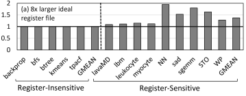
To illustrate the potential benefit of using a large register file, Figure 3(a) plots performance (in IPC) for a high-capacity register file in the ideal case, which has the same latency as the baseline register file from Table2. We categorize our workloads into two groups: register-insensitive and register-sensitive. Register-insensitive workloads are the ones where the register file size is not the bottleneck for higher TLP; i.e., increasing the register file size does not improve TLP. We observe that increasing the register file size from 256KB to 2MB without increasing the register file access latency, improves IPC by 10%-95% (37%, on average) for register-sensitive workloads. We find that the IPC improvements are due to both more registers per thread and more warps executing in parallel. Figure 3(b) plots performance (in IPC) for a high-capacity register file implemented using TFET-SRAM, normalized to the baseline register file from Table 2.111We choose a 2MB TFET-SRAM register file as it consumes a similar amount of power as our baseline 256KB register file (see Table 2). We observe that when real latencies are modeled, much of the gain from higher capacity and TLP is offset by higher latency, and overall performance reduces despite the higher register file capacity. We conclude that register file access latency is important for performance and should be kept in check while increasing register file capacity.
 |
 |
2.3. Register File Caching
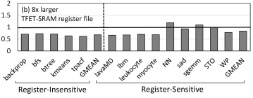
One method to increase the size of the register file while keeping access latency low is to cache registers in a smaller structure, i.e., register file caching. Although there is significant previous work on register file caches for CPUs (Swensen and Patt, 1988; Nuth and Dally, 1995; Yung and Wilhelm, 1995; Cruz et al., 2000; Balasubramonian et al., 2001; Oehmke et al., 2005; Zeng and Ghose, 2006; Jones et al., 2009; Shioya et al., 2010; Cooper and Harvey, 1998; Mirhosseini et al., 2019b), and vector processors (Russell, 1978; Kapasi et al., 2002; Borch et al., 2002), register file caching has not been thoroughly investigated in GPU designs. Gebhart et al. (Gebhart et al., 2011a) are the first to introduce register file caches for GPUs to filter some of the accesses to the main register file and thus reduce the dynamic access energy of the main register file. The authors’ design works almost the same way as a conventional cache structure and exploits temporal locality. However, as Figure 4 shows, for a 16KB register cache, the register cache hit rate is low: between 8% and 30%.
We find that the hardware register cache hit rate is low due to the following reasons:
-
(1)
Different warps can displace each other’s registers in the cache due to the high warp switching rate in GPUs. This thrashing effect is also observed in SMs’ local data caches (Kayiran et al., 2014; Xie et al., 2015; Rogers et al., 2012; Mirhosseini et al., 2017; Gebhart et al., 2011a; Kayıran et al., 2013; Sethia and Mahlke, 2014; Sadrosadati et al., 2017; Mirhosseini et al., 2019a; Bakhoda et al., 2010b; Jang et al., 2015; Bakhoda et al., 2010a, 2013; Sethia et al., 2013; Lee et al., 2010a; Jog et al., 2013b, a; Tian et al., 2015; Mirhosseini et al., 2016; Ausavarungnirun et al., 2015; Xie et al., 2013; Li et al., 2015; Nematollahi et al., 2018; Khorasani et al., 2018; Jeon et al., 2019).
-
(2)
We find that many registers are used to only communicate results between a few instructions. As a result, these registers do not have good temporal locality.
-
(3)
There is no notion of ”spatial locality” in register accesses (i.e., there is no logical order among different registers).
Follow-up work (Gebhart et al., 2011b) proposes a software-managed hierarchical register file (SHRF) that aims to reduce data movement between the main register file and the register cache. However, as the main objective is to reduce dynamic energy consumption of the baseline large monolithic register file, the authors (Gebhart et al., 2011b) aim to reduce the total number of accesses to the main register file, regardless of whether or not those accesses occur during the execution of a warp. In particular, SHRF reduces the extra register file accesses caused by register file cache write-back/reloads, by adding specialized instructions, aided by a new register allocation mechanism, to manage register movement. However, Figure 4 shows that the software approach does not significantly improve the hit rate compared to a baseline hardware register cache (Gebhart et al., 2011a) as it mostly focuses on reducing the number of background (i.e., write-back/reload) register accesses, rather than accesses that are needed by program instructions.
2.4. Summary and Goals
In this work, we leverage two observations we have provided in this section. First, the register file is one of the limiting factors in the scalability of GPUs in terms of TLP. Second, making the register file considerably larger is very difficult without sacrificing either latency or power consumption. Register caching can reduce the register access latency and thus enable aggressive power optimization techniques without degrading GPU performance. However, register caching has not been thoroughly studied in the context of GPUs and the existing schemes mainly aim to reduce power consumption, rather than completely hide the main register file access latency. Therefore, these designs are inefficient as they do not offer high register cache hit rates. In fact, they hurt performance if used with considerably slow main register files (see § 7).
In this paper, we aim to architect a latency-tolerant hierarchical register file for GPUs that can have very high capacity. Our goal is to 1) enable very high-capacity yet also high-latency main register files, while improving performance, and thus 2) open the design space for many power/area optimization techniques in the main register file that likely increase the register access latency (and thus would otherwise be unacceptable).
3. Latency-Tolerant Register File
To make the register file very high capacity and at the same time latency-tolerant, we propose a new register file caching mechanism that aims to 1) bring the warps’ registers into the register file cache before they are accessed by the warps (i.e., register prefetching) and 2) service all register accesses from the register file cache. As a result, the warps see the latency of a fast register cache and not the slow main register file. We find that a near-perfect register prefetching mechanism can be implemented based on two key observations. First, the register working-set is known at compile-time as there is no indirection or aliasing in register accesses. Second, long register access latency can be hidden by the execution of other active warps.
LTRF takes advantage of these two observations that enable a new register prefetching scheme. § 3.1 provides an overview of our register prefetching scheme. § 3.2 and § 3.3 provide an overview of the architectural and compiler support required for our software-driven prefetching scheme, respectively.
3.1. Register Prefetching Scheme
We define a prefetch operation to specify which registers should be prefetched from the main register file. A prefetch operation brings the register working-set of a subgraph of the application control flow graph (CFG) into the register cache. The working-set is composed of the registers that, depending on the dynamic control flow, might be accessed between two prefetch operations. We call subgraphs of the CFG created by prefetch operations (bounded by prefetch operations) prefetch subgraphs. Finding an optimal placement of prefetch operations is not only impossible in polynomial time, but also requires information available only during runtime because of dynamic warp interleavings. We propose a heuristic algorithm that employs the concept of intervals (Hecht, 1977), subgraphs of the CFG with a single entry point, which offers compile-time analysis within a reasonable amount of time. We modify the classic interval analysis algorithm, used to find the subgraphs of the CFG with a single entry point, and introduce the concept of register-intervals as suitable prefetch subgraphs for prefetching registers. A register-interval is a subgraph of the CFG that 1) has a single control flow entry point and 2) requires, at most, a given number of registers.
Our scheme brings the register working-set into the cache at the beginning of each register-interval and guarantees that all register accesses made inside that register-interval will be serviced from the register file cache. See § 3.2 and 3.3 for more details about the proposed register prefetching scheme.
3.2. Architectural Support
To reduce the register file cache size, we limit the number of active warps that run concurrently and maintain a pool of inactive warps; the inactive warps remain dormant and are not allocated space in the register file cache. Furthermore, we partition our register file cache and allocate each partition to an active warp, thus preventing active warps from contending for register file cache space, and thus from evicting each other’s registers. We size the dedicated caching space for each warp according to the maximum number of registers the warp can access throughout the execution of a prefetch subgraph. This parameter also sets an upper bound for the size of a prefetch subgraph working-set. By ensuring no register cache evictions occur during the execution of a prefetch subgraph, we guarantee that register movement happens only with prefetch operations or when a warp becomes active/inactive.
We deploy a two-level warp scheduler, similar to the one used in (Gebhart et al., 2011a; Narasiman et al., 2011), to schedule execution of active warps. The scheduler issues instructions from active warps in a fair manner (e.g., round-robin). Whenever a warp encounters a long latency operation, such as a data cache miss, it becomes inactive and gets replaced by another one from the active pool. The two-level scheduler enables the use of a smaller register file cache that needs to accommodate only the working-sets of the active warps, and a warp’s register working-set is swapped in and out of the register file cache as warp becomes active/inactive.
Reducing the number of active warps provides two positive benefits: it 1) does not limit TLP since inactive warps still maintain live state in the main register file, and thus can be quickly activated, 2) can potentially improve performance by reducing the L1 data cache thrashing effect and by preventing all warps from stalling at the same time (Kayıran et al., 2013; Sethia and Mahlke, 2014; Rogers et al., 2012; Kayiran et al., 2014; Narasiman et al., 2011). In LTRF, warp activations are not cost-free as the register working-set of the inactive warp needs to be prefetched before the warp becomes active. Hence, if we cannot hide the warp activation latency, we might negatively affect performance. In § 7.2, we quantitatively show that this is not the case. LTRF requires a small number of active warps to hide the warp activation latency, allowing a GPU to tolerate higher latency accesses to the main register file.222We discuss the design of the main register file and the register cache in detail in the conference version (Sadrosadati et al., 2018).
Prefetch operations use bit-vectors to identify the registers that should be cached for each prefetch subgraph, enabling support for various cache sizes. The prefetch bit-vector size is equal to the maximum number of registers the CUDA compiler can allocate to a thread. For example, in the latest CUDA versions, the compiler can allocate up to 256 registers to each thread, requiring a 256-bit vector for each prefetch operation. The instruction fetch unit needs to know in advance when it is going to process a prefetch bit-vector. We consider two approaches. The first embeds an extra bit in each instruction to indicate whether a prefetch bit-vector follows that instruction. Prior work (Gebhart et al., 2011b) has similar requirements and the authors show that, in general, the cost of embedding the extra bit is negligible. The second approach is to add an explicit instruction that is always followed by the bit-vector.333We show in the conference version (Sadrosadati et al., 2018) that code-size and performance overheads are negligible with either of the approaches.
When a warp becomes inactive, we must keep track of which registers should be written back and refetched once the warp becomes active again. In LTRF, we simply write back and refetch the entire register working-set of the active prefetch subgraph.
In order to improve the efficiency of the basic LTRF design, we devise operand-liveness aware LTRF (called LTRF+), which considers the liveness of the registers to save register file cache space. The key idea of LTRF+ is to avoid writing-back/re-fetching dead registers. To this end, each read operand has to be extended with an additional bit, called the dead operand bit as defined in (Gebhart et al., 2011a), which indicates whether the corresponding operand will be dead after the execution of the corresponding instruction. This information can be conservatively known at compile-time, using static liveness analysis. These bits are used to update the liveness bit vector. The liveness bit vector keeps track of the liveness status of all registers at the current point of execution. A register becomes live when it is written to and dead when an instruction indicates it is dead via the dead operand bit. When a warp becomes inactive, LTRF+ writes back only the live registers to the main register file. When a warp becomes active, LTRF+ fetches only the live registers from the main register file. LTRF+ does not read the dead registers from the main register file since their first access, if any, will be a write, and LTRF+ needs to only allocate space for them in the register file cache.
3.3. Compiler Support
When a warp reaches the beginning of a prefetch subgraph, it is paused until all of its working-set registers are loaded into the register cache. Therefore, prefetch operations may have long latencies that can potentially impose large performance overheads, and hence, they should happen infrequently. In order to address this issue, we introduce register-intervals as effective prefetch subgraphs and partition the CFG into register-intervals. A register-interval is a subgraph of the CFG with only two constraints. First, it needs to have only one control flow entry point. Second, the number of registers used in a register-interval should not exceed the size of a partition in the register cache.444We provide dedicated space for each active warp in the register file cache. The primary difference between register-intervals and other similar concepts, such as strands (Gebhart et al., 2011b), is that complex control flow structures (e.g., backward branches) are allowed inside a register-interval and they do not cause the termination of the register-interval. By relaxing such constraints, register-intervals provide two main benefits. First, register-intervals can have more static instructions and thus the number of prefetch operations can be minimized. Second, our mechanism aims to fit a loop within a single register-interval in order to increase the dynamic length of the register-intervals.
We employ classic interval analysis methods (Hecht, 1977) to form register-intervals. The original interval concept (Hecht, 1977), used in classic compiler algorithms, partitions the CFG into smaller disjoint subgraphs, each with exactly one entry point. These intervals are typically used to identify loops and determine if the CFG is reducible. We constrain the formation algorithm to guarantee that the register working-set of each interval can fit into a register file cache partition. As a result, the register-intervals constructed by our algorithm might be smaller than the intervals formed by the original algorithm and may terminate at arbitrary points. Thus, we modified the original algorithm to construct intervals at arbitrary starting points.
Input: Application Control Flow Graph (CFG)
Output: Register-Interval CFG
Our register-interval formation algorithm is a multi-pass algorithm. Algorithm 1 shows the first pass. The algorithm tries to compose register-intervals with as many basic blocks as possible. Therefore, it initializes the first register-interval with the entry basic block (line 8) and iteratively attempts to add subsequent blocks to it (lines 9-25). A candidate block must satisfy two conditions to be successfully added: 1) it must be entered only from the current register-interval, 2) the register file cache space allocated for a warp must be enough to house both the active registers already in the register-interval and the ones added by the new block. The algorithm stops when it cannot find any basic blocks that meet these conditions (line 13). After it finishes the first register-interval, it creates new register-intervals out of all the basic blocks with incoming edges from that register-interval (lines 18-24). When a register-interval is completely formed, all of the basic blocks that have incoming edges from that register-interval become new register-intervals’ headers. If a single basic block’s active registers do not fit into the remaining register file cache space for that register-interval, the basic block is split across two or more register-intervals (lines 30-37). We also split the basic blocks at function calls (each function call becomes a separate register-interval). Algorithm 1 is not multi-pass and ends when all basic blocks of the control flow graph are assigned to register-intervals. After executing Algorithm 1, the CFG is transformed into a Register-Interval CFG where the nodes represent the register-intervals rather than basic blocks.
Algorithm 2 shows the second pass of our register-interval formation algorithm. This pass reduces the Register-Interval CFG into a smaller number of register-intervals. It works similarly to the first pass, with the difference that it never splits register-intervals. Instead, it merges two register-intervals if 1) one of them can be reached only from the other and 2) the union of their register working-sets still fits into the allocated register file cache space (lines 12-15). The second pass is repeated until the CFG can not be reduced anymore. After each pass of Algorithm 2, there are two possible scenarios: 1) the graph is not reduced, and 2) the graph is reduced. In the first scenario, Algorithm 2 terminates. In the second scenario, Algorithm 2 runs again on the reduced register-interval control flow graph. However, this cannot last forever, as in the worst-case (worst case in terms of algorithm execution time), the graph will be reduced to a one-node graph, which cannot be reduced more.
Input: Register-Interval CFG
Output: Reduced Register-Interval CFG
The only control flow constraint imposed by intervals is that a node can only join an interval when all of the incoming edges to the node come from that interval. As a result, backward edges and thus loop headers always create new intervals.555This is true only for reducible CFGs with natural loops where the loop has only one entry point (Hecht, 1977). However, this is usually the case as standard languages can usually only represent natural loops (except in some cases with irregular control flow structures, such as GOTO) and compiler infrastructures only produce reducible CFGs (Lattner and Adve, 2004). This key feature of intervals makes them ideal subgraphs for our purpose. By starting a new register-interval for each loop, Algorithm 2 maximizes the probability that an entire loop can fit into the register-interval, thereby minimizing the number of prefetch operations to one for the entire loop.
The primary role of the second pass is to prevent the mentioned control flow constraint from splitting large register-intervals into multiple smaller ones. As an example, consider the two nested loops in Figure 5. Assuming the entire register working-set of the graph fits in the register file cache, in the first pass, basic block ”A” forms register-interval 1. Basic block ”B” cannot be merged with register-interval 1 as it has another incoming edge from basic block ”C”. Therefore, basic block ”B” forms a new register-interval, named register-interval 2. Basic block ”C” can be merged into register-interval 2 as basic block ”C” has only one incoming edge from register-interval 2. As a result, the innermost loop becomes a separate register-interval but it cannot be merged into the outermost loop. In the second pass, register-interval 1 can be merged into register-interval 2 as register-interval 1 has only one incoming edge from register-interval 2. Thus, the whole outermost loop can be reduced to a single register-interval. Each repetition of the second pass of the algorithm reduces the depth of a nested loop by one if the resulting register working-set is small enough to fit in the register file cache.

4. Resolving Register Bank Conflicts
Register prefetching latency affects LTRF effectiveness because long latencies call for a higher number of active warps and larger register-cache capacities. Therefore, it is crucial to reduce the register prefetching latency in order to minimize LTRF’s register-cache size. One of the main factors that greatly affects register prefetching latency is register bank conflicts during prefetching operations. When several registers of a register-interval reside in the same register bank, they cause register prefetching to happen serially, significantly increasing the register prefetching latency.
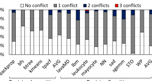
To evaluate the probability of register bank conflicts while LTRF prefetches registers’ contents, we calculate the number of registers that reside in the same register bank in each register-interval. We assume that the maximum number of allowed registers in each register-interval is 16, and there are 16 main register file banks. A register-interval has no register bank conflict if all registers of its register working-set reside in different main register file banks. A register-interval has N register bank conflicts if at most N+1 registers reside in the same register bank. Figure 6 shows the distribution of the number of register bank conflicts in register-intervals for different register-insensitive and register-sensitive workloads. We make two key observations. First, about 60% and 80% of register-intervals have at least one register bank conflict for register-insensitive and register-sensitive applications, respectively. Second, we observe up to three register bank conflicts for our workloads. We conclude that we can greatly reduce the prefetching latency by resolving register-bank conflicts.
In the rest of this section, § 4.1 describes the register-bank conflict problem in more detail and provides the basic insight of our approach, which is careful register bank assignment to resolve register bank conflicts, § 4.2 presents our proposed mechanism to resolve register bank conflicts in register-intervals, and § 4.3 elaborates on our mechanism using an example.
4.1. Register Bank Assignment
Register allocation is one of the most important optimization phases in compilers that directly affects the performance of the generated code (Aho, 2003; Chaitin et al., 1981; Briggs, 1992; Poletto and Sarkar, 1999; Hack et al., 2006). As the register file in a GPU is multi-banked, the register allocation mechanism should attempt to allocate the registers to different banks in order to benefit from multi-banking. Prior attempts on compilers produce bank-conflict-free register accesses by performing a register bank assignment pass in addition to register allocation (Zhuang and Pande, 2003; Patney and Dally, 2013; Lai and Seznec, 2013). Prior works build a Register Conflict Graph whose nodes are live ranges of the program and two nodes are connected if there is a conflict between them, e.g., two source operands of an instruction.
The problem we seek to solve is different. Our primary goal is to perform a bank assignment wherein all registers in the working-set of each register-interval reside in different register banks, hence decreasing the register prefetching latency. To specify our problem, it is necessary to define a key concept called register-live-range. A register-live-range is a chain of common uses of a specific register which specifies the liveness of the register in register-intervals. The main purpose of introducing register-live-ranges is to track the liveness of values and registers across different register-intervals. In other words, register-live-ranges enable us to guarantee the correctness of the final register bank assignment with respect to the live values in registers. The input to our problem is a set of register-live-ranges specified by the register-interval CFG. Our problem is to map each register-live-range to one of register banks in such a way that those with common register-intervals reside in different register banks.
We propose a new register bank assignment technique, called register renumbering, as a compiler optimization pass after the register allocation and register-interval formation phases. Our solution is analogous to prior bank assignment proposals. As mentioned before, register-live-ranges can be shared between different register-intervals and it is not straightforward to assign a register bank to each register-live-range. Hence, how we model our problem is important. We use graph coloring as a simplification abstraction. We model our bank assignment problem as a graph coloring problem which restricts register-live-ranges to reside in different register banks if they have a live value in the same register-intervals. The next section explains our mechanism in more detail.
4.2. Register Renumbering Mechanism
Figure 7 presents an overview of the compiler support of LTRF, including the register renumbering mechanism. As discussed before, the main goal of the register renumbering technique is to minimize register bank conflicts during prefetch operations as much as possible. This technique is employed at compile-time after register allocation and register-interval formation phases. The output of this optimization pass is register-intervals with minimal register bank conflicts. In some cases, register bank conflicts cannot be resolved unless we spill some of the register-live-ranges to main memory. We do not produce any spill code in the register renumbering phase, since the register prefetching latency would be increased significantly due to accessing the register-live-ranges spilled in main memory.

We model our problem as a graph coloring problem. To this end, we build an appropriate graph, called the Interval Conflict Graph (ICG), containing all constraints of our problem. In ICG, the nodes are register-live-ranges, and the edges represent conflicts between adjacent nodes. In other words, two nodes are connected if the two corresponding register-live-ranges have live values in same register-intervals. If we assume the number of available colors is equal to the number of register banks in a register file, a valid ICG coloring is one where all adjacent nodes have different colors, i.e., conflicting register-live-ranges receive different colors. This coloring represents our desired bank assignment with minimal register bank conflicts.
Our register renumbering mechanism has four phases (see Figure 7):
-
(1)
Building Register-Live-Ranges. This phase identifies register-live-ranges as the chains of definitions and uses of registers. We then identify which register-live-range is included in which register-interval(s).
-
(2)
Building ICG. Nodes of ICG are register-live-ranges and there is an edge between two nodes if they are included in at least one common register-interval.
-
(3)
Coloring ICG. This phase colors the ICG with colors, where is the number of register banks. The problem of k-coloring a graph is NP-complete (Cormen et al., 2009; Kleinberg and Tardos, 2006). Therefore, we use a heuristic algorithm for graph coloring to create the colored graph in a reasonable amount of time. The heuristic algorithm that we employ is devised by Chaitin et al. (Chaitin et al., 1981). The algorithm requires time, where is the number of register-liver-ranges and is the number of edges in the ICG (Chaitin et al., 1981). This algorithm does its best to color the graph in a balanced manner, i.e., colors are almost equally used. This key feature of this algorithm enables us to perform a balanced bank assignment that minimizes the register bank conflicts.
-
(4)
Renumbering. The final phase of the algorithm is renumbering all registers based on their ICG color. In this phase, we assume no register has been allocated to register-live-ranges and we have a set of free registers. Whenever we want to allocate a register to a register-live-range, we choose one of the free registers of the register bank specified by the colored ICG. This approach guarantees the correctness of the code as register-live-ranges contain all uses of a specific register. Note that each color in the colored ICG represents one of the register banks.
4.3. A Walk-Through Example
We elaborate on our register renumbering mechanism using a simple example. Listing 1 and Figure 8 show a PTX code example and the corresponding register-interval CFG, respectively. This code example compares two arrays with 100 elements and sets a register, i.e., R6, if all corresponding elements of the two arrays are the same. For the sake of simplicity, we assume that each register-interval can have up to four registers, and there are four main register banks, each containing two registers. Figure 8 shows that the prefetch operation of register-interval #2 prefetches four registers, including R0, R1, R4, and R5, which results in register bank conflicts as R0 and R1 are in register bank #0 and R4 and R5 are in register bank #2 (See the right side of Figure 8). As a result, performing the prefetch operation in register-interval #2 needs two serial register bank accesses. A similar scenario happens in register-interval #3. To resolve the register bank conflicts, we perform our register renumbering pass on this code.
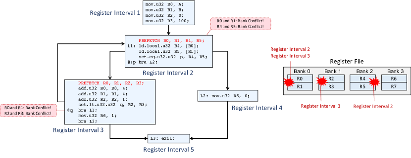
Figure 9 (bottom left side) shows the ICG of the example code in Listing 1. The ICG shows that, for example, R0 and R1 cannot reside in the same register bank as R0 and R1 are both live at the beginning of register-interval #2. We color the ICG with colors, i.e., four colors in the example. We consider green, blue, yellow, and red colors for the main register banks #0, #1, #2, and #3, respectively (See Figure 9 on top). Figure 9 (middle) shows the colored ICG specifying which bank each register should reside in to minimize register bank conflicts. We renumber each register according to its ICG color. Figure 9 (right side) shows the ICG after renumbering. For example, R1 is renumbered to R2 to resolve its bank conflict with R0. Figure 10 shows the CFG of program after register renumbering. In the new CFG, all register bank conflicts existing in register-interval #2 and register-interval #3 are completely resolved.


5. Hardware Implementation
In this section, we discuss the hardware implementation of LTRF in detail.
5.1. Register File Microarchitecture
Register File Cache. Figure 11 illustrates an example LTRF architecture. We show our added components to the baseline register file architecture in orange color. The register file cache is composed of banks (e.g., 16 banks in the figure) where each bank hosts registers (e.g., 8 1024-bit registers in the figure). LTRF interleaves registers belonging to a single warp across the cache banks, and hence, each register bank houses no more than one register of a warp. Register file cache banks are connected to the operand collectors via a crossbar.
Warp Control Block. A key structure in LTRF design is the Warp Control Block (WCB), shown in Figure 12. The purpose of the WCB is to maintain metadata for each warp required for controlling the register prefetching process and finding the position of the architectural registers in the register cache. To this end, WCB is composed of the register cache address table, the working-set bit-vector, and the liveness bit-vector. The register cache address table is a 256-entry table per warp that keeps the register file cache bank number for each warp’s architectural registers. The register cache address table has as many entries as the maximum number of architectural registers allocated to a warp. All cached registers of a warp have the same offset in all register file cache banks. Thus, for each register, the table only needs to keep track of the -bit (e.g., 4-bit in Figure 12) index of the register file cache bank number where that register is located. WCB also contains one -bit (e.g., 3-bit in Figure 12) entry to track the offset of that warp’s registers inside the banks (called warp-offset address). The working-set bit-vector holds a valid bit for each register to indicate whether it has already been prefetched during the prefetch phase. Since most of the instructions have two read operands, we provide two read ports for each register cache address table. Any instruction that operates on more than two operands must fetch the register file cache addresses of all operands over multiple cycles.

In LTRF+, which considers the liveness of operands, each warp maintains a liveness bit-vector that keeps track of the liveness of each architectural register in the WCB, as depicted in Figure 12. This vector is initially cleared (i.e., all registers are marked as dead) when the warp starts execution, and it is updated as the warp executes (§ 3.2).
Operand Collector Modifications.
We augment each operand collector (Figure 11, right) with
-bit (e.g., 4 bits in the figure) bank number and -bit (e.g., 3 bits in the figure) warp-offset address to determine the location of each architectural register in the register file cache.
Register File Cache Access. As multiple warps may still try to access the same bank at any given cycle, we use an arbiter, as in conventional GPU register files, to arbitrate between accesses to register file cache banks and to resolve bank conflicts.
When an operand collector is allocated to a warp, it probes the register cache address table in the corresponding WCB to get the locations of registers inside the register cache. After reading the registers’ locations, the operand collector participates in the arbitration phase to 1) resolve bank conflicts and 2) access the register file cache to read the operands.
5.2. Software-Triggered Prefetch Mechanism
Executing Prefetch Operations. When a warp reaches a prefetch operation, the GPU must load the warp’s registers into the register file cache as indicated by the prefetch bit-vector. Initially, the prefetch bit-vector is decoded into a list of indices (IDs) of registers that need to be loaded. Once the register indices are identified, they must be allocated space in the register file cache, and the warp’s register cache address table in the WCB must be properly filled. After allocating register file cache space, the registers can be read from the main register file to fill the register cache. When a register is prefetched completely, the corresponding valid bit in the WCB is set. After all registers indicated by the prefetch bit-vector are prefetched, the warp becomes ready to execute, and all subsequent register accesses of that warp are served from the register file cache. In LTRF+, whenever a warp performs a prefetch operation, it queries the liveness bit-vector and prefetches only the registers that are marked as live. For dead registers, it is sufficient to allocate the register file cache space, without fetching data.
Register File Cache Space Allocation. Every cached register in a register-interval must be assigned a place in the register file cache. In our design, this mechanism is equivalent to allocating one register file cache bank for each cached register as we interleave the registers of a single warp across banks to minimize register file cache bank conflicts. We employ the Address Allocation Unit, depicted in Figure 13, for each warp to implement this mechanism. The Address Allocation Unit is composed of two queues: the unused queue keeps track of free banks, while the occupied queue keeps track of allocated banks. Initially, the unused queue is full, and the occupied queue is empty. On an allocation, we allocate the head of the unused queue to the new register and move that entry to the occupied queue. On a deallocation, we move the deallocated register entry back to the unused queue. The same mechanism is used to allocate warp-offset addresses to warps. There, we use a global Address Allocation Unit that is shared by all warps.

Interconnect. We use an -bit arbiter (e.g., 8-bit arbiter in Figure 11, left) to arbitrate among warps to fill the register file cache. Registers are loaded into the register file cache from the main register file via a crossbar network. In order to design this crossbar, we calculate the number of accesses to the main register file in LTRF and the baseline architecture. Our experimental results show that LTRF reduces the number of accesses to the main register file by 4-6 (as most of the accesses are serviced through the register file cache) and the bandwidth of the 1024-bit crossbar in the baseline architecture without register caching (Leng et al., 2013; Bakhoda
et al., 2009) is utilized by up to 85%. As a result, we can reduce the bandwidth of the main register file crossbar by 4 without hurting performance. On the downside, the narrower crossbar would exhibit a traversal latency 4 larger (from 1 cycle to 4 cycles) than a wide crossbar in typical scenarios, and far larger latency when the crossbar is saturated and queuing effects become dominant. However, due to the latency-tolerant nature of our design and the fact that register file access latencies are dominated by bank access times rather than crossbar traversals, we find that the longer traversal latency of a narrower crossbar is not a significant performance issue. Because warp registers are interleaved across the register cache banks, LTRF improves the parallelism of accesses in the interconnect.
Warp Stall. A warp that is stalled becomes inactive and loses its slots in the register file cache. In that case, it must perform three steps. First, it writes back its live registers to the main register file. Second, it releases its register file cache slots. Third, it clears all the valid bits in the register cache address table of the WCB. Whenever a warp goes from being inactive to active, and it finds itself in the middle of a register-interval, it must refetch all its specified registers in its working-set bit-vector that are still live from the main register file. This is done using the warp’s working-set and liveness bit-vectors in WCB.
5.3. Overheads
Code Size. LTRF increases the average code size by 7% if only prefetch bit-vectors are inserted into the code and 9% if the bit-vectors are accompanied by prefetch instructions. Note that, in order to be able to only insert the bit-vectors into the code, the ISA has to be redesigned and an extra bit has to be embedded into all instructions, as explained in §3.2. To measure the effect of the increased code size on the GPU performance, we execute the original and the modified programs on the baseline architecture using GPGPU-Sim (Bakhoda
et al., 2009). Our experimental results show that the larger code size results in 0.2% average (up to 1%) performance degradation, which is negligible. We do not add a new instruction to pass liveness information to hardware. We use the same mechanism as the prior work (Gebhart et al., 2011a), which embed liveness information in the instruction using free spaces in the instruction code. As a result, marking dead registers does not increase the code footprint and the number of executed instructions.
Storage Cost. LTRF requires a WCB for every warp, shown in Figure 12. Each WCB contains one 5-bit entry per architectural register, 3-bit for the warp-offset address, and working-set and liveness bit-vectors, each with one bit per register. The total storage overhead of the WCB for each SM in an example modern architecture, which supports 64 warps with 256 registers per warp, is 114880 bits (), around 5% of the area consumed by the 256KB baseline register file.
Latency Overhead. According to our analysis with CACTI (Muralimanohar et al., 2009), the WCB can be accessed within one extra clock cycle. Hence, it adds negligible performance overhead in accessing the registers.
Area/Power Cost.
In order to measure the area and power overheads of LTRF, we functionally model all the added components (i.e., WCB, the additional crossbar, address allocation units, the arbiter, additional entries in the operand collectors, and register file cache) in GPU-Wattch (Leng et al., 2013). In total, LTRF occupies 16% more area than our baseline GPU register file (i.e., Configuration #1 in Table 2) using the same main register file size and technology. In terms of power consumption, despite the added structures, LTRF consumes 23% less power compared to the baseline register file. LTRF’s improvement in power consumption is due to reducing the number of accesses to the main register file by 4-6.
6. Methodology
Simulation. We evaluate our techniques using the GPGPU-Sim V3.2.2 (Bakhoda et al., 2009) cycle-level simulator for GPUs. Table 3 provides the details of our baseline GPU configuration. We model our baseline after an NVIDIA Maxwell-like architecture (NVIDIA, 2014b). We modify the microarchitecture of the conventional register file in GPGPU-Sim to implement the LTRF microarchitecture depicted in Figure 11.
| Number of SMs | 24 |
|---|---|
| Core clock | 1137 MHz |
| Scheduler | Two-level (Gebhart et al., 2011a; Narasiman et al., 2011) |
| Number of warps per SM | 64 |
| Register file size | 256KB per SM (65536 registers) |
| Register file cache size | 16KB per SM (4096 registers) |
| Shared memory size | 64KB per SM |
| L1D Cache | 4-way, 16KB, 128B line |
| L1I Cache | 4-way, 2KB, 128B line |
| LLC | 8-way, 2MB, 128B line |
| Memory Model | 8 GDDR5 MCs, |
| FR-FCFS (Zuravleff and Robinson, 1997; Rixner et al., 2000), 2700 MHz | |
| GDDR5 Timing | =12, =12, =40, |
| (in nanoseconds) | =28, =12, =6 |
| Number of active warps | 8 per SM |
| Number of registers | 16 |
| in a register-interval |
We use the compiler in GPGPU-Sim to implement our software prefetching mechanism. To this end, we process the CFG of the register-allocated PTX code to form the register-intervals666We open source the C implementation of register-interval creation in (Group, 2018). and insert prefetch bit-vectors at the start of each register-interval.
Benchmarks. We run 35 benchmarks from CUDA SDK (Bakhoda
et al., 2009), Rodinia (Che et al., 2009), and Parboil (Stratton et al., 2012) benchmark suites and classify them into two groups, register-sensitive and register-insensitive, based on whether or not the register file limits the achievable TLP. Enlarging GPU register file improves the thread-level parallelism of register-sensitive applications. However, not all register-sensitive applications benefit the same from higher thread-level parallelism in terms of GPU performance (see § 7.1 for more detail). We randomly select nine workloads from the register-sensitive group, and five workloads from the register-insensitive one.
Comparison Points. We evaluate (1) a baseline (BL) architecture that models a GPU with a conventional non-cached register file. To provide a fair comparison of this baseline to other register file cache based designs, we add the amount of space dedicated for the register file cache in LTRF (16KB) to the main register file capacity in the BL architecture, (2) a design with a 16KB register file cache (RFC) without any prefetching mechanisms, similar to the architecture proposed in (Gebhart et al., 2011a), (3) LTRF with a 16KB register file cache. (4) LTRFconf, an enhanced version of LTRF in which, we reduce the register bank conflicts in performing prefetch operations using a compiler pass after register-interval creation pass (§ 4). (5) a GPU with an Ideal register file architecture that allows us to increase the register file capacity to any size (i.e., 8 in our evaluations) with no latency overhead. Please note that all these designs have 24 SMs and 64 warps per SM.
Design Points. To show the benefits of LTRF, we select different memory technologies (i.e., TFET (Li et al., 2013) and DWM (Venkatesan et al., 2014)) as use-cases. The reason for selecting different memory technologies is that they let us evaluate a wider range of access latencies; we believe that using different memory technologies is one of the concrete potential futuristic use-cases since these technologies are finding their ways into commercial products due to limitations of existing technologies in scaling to smaller dimensions (Lee
et al., 2009a; Lee et al., 2010b; Qureshi
et al., 2009; Kültürsay et al., 2013; Tavakkol et al., 2018). Yet, our optimizations do not depend on the existence of a new memory technology. We can have large register files where LTRF would be useful even in conventional technologies by paving the way for different register file optimization techniques, such as register file compression (Lee
et al., 2015; Vijaykumar
et al., 2015; Pekhimenko et al., 2016, 2015), register file virtualization (Vijaykumar et al., 2016; Jeon
et al., 2015; Khorasani et al., 2018; Kloosterman et al., 2017), and register file power-gating (Abdel-Majeed and
Annavaram, 2013; Hsiao
et al., 2014; Sadrosadati et al., 2019; Kayiran et al., 2016; Mirhosseini et al., 2015; Sadrosadati et al., 2015). We increase the register file size from 256KB to 2MB by using the register file configurations #6 and #7 from Table 2. Configuration #6 allows us to increase the register file size by 8 while keeping the power consumption almost unchanged. Configuration #7, on the other hand, results in less power/area consumption compared to the baseline SRAM-based 256KB register file. We use these design points as realistic baselines for our performance analysis.
We carefully model the register prefetching latency. Three important factors that affect prefetching operation delay are (1) the register bank access latency, (2) the register bank conflict, and (3) the transferring latency. We model the register bank access latency of each memory technology using CACTI (Muralimanohar et al., 2009) and NVSim (Dong
et al., 2012). We then import the calculated numbers to the GPGPU-Sim (Bakhoda
et al., 2009) to consider the effect of register bank conflicts, as well. Regarding the transferring latency, we use the booksim simulator (Jiang et al., 2013a) embedded in the GPGPU-Sim.
Performance Metrics. We use IPC as the performance metric to evaluate different register file designs. We evaluate our compiler algorithms by measuring the size of the generated register-intervals.
7. Evaluation
We present the effectiveness of five different mechanisms: BL, RFC, LTRF, LTRFconf, and Ideal. § 7.1 shows the overall effect of LTRF on GPU performance. § 7.2 analyzes the effectiveness of LTRF at tolerating the latency of the main register file. § 7.3 evaluates the number of register blocking events in LTRF and LTRFconf. § 7.4 provides sensitivity analysis on the size of the register file cache. § 7.5 analyzes the number of instructions in register-intervals. § 7.6 provides a comparison between LTRF and other software-managed register caching schemes.
 |
7.1. Overall Effect on GPU Performance
To evaluate the effect of larger register files on GPU performance, we increase the register file size from 256KB to 2MB by using the register file configurations #6 and #7 from Table 2. Figure 14 compares the normalized IPC of BL, RFC, LTRF, and LTRFconf designs when used on top of these two configurations. In this figure, we normalize the IPC results to the IPC results of the baseline architecture of configuration #1 in Table 2, without any register caching, with one modification: we add the register file cache capacity (i.e., 16KB) used in the other mechanisms to the 256KB register file size of configuration #1. Ideal bars show the IPC of an idealized version of configuration #1 with 8 the register file capacity but no increase in latency (i.e., access latency remains constant after increasing register file size by 8). We make three major observations. First, LTRF provides almost the same IPC performance as the Ideal design when we employ configuration #6. LTRF improves IPC by 32%, on average. The IPC improvement of LTRF is due to two main reasons. (1) The larger register file enables both more registers per thread and more warps executing in parallel. (2) LTRF effectively tolerates the higher access latency of configuration #6. Second, for the register-insensitive workloads that do not benefit from a larger register file (e.g., btree and kmeans), the performance overhead of increasing the register file size is minimal if we use LTRF and LTRFconf as opposed to RFC. Third, LTRFconf improves the performance of LTRF by an average 3.8% and 4.8% for configurations #6 and #7, respectively. These results clearly show the positive effect of reducing the number of register blocking events on LTRF performance. Fourth, LTRF and LTRFconf effectively enable the use of configuration #7, which reduces the register file area by 75%. For this configuration, LTRF and LTRFconf improve performance by 28% and 34% over the baseline, on average, respectively. We conclude that LTRF enables a high-capacity and high-latency main register file while providing high performance.
7.2. Effect of LTRF on Register File Access Latency
To show the effectiveness of LTRF at tolerating register file access latency, we define a new metric: the maximum tolerable register file access latency. This is the relative latency777Relative to the baseline of configuration #1 with 16KB additional register file capacity of the main register file that leads to at most 5% performance (IPC) loss for each workload we examine. Note that this metric is different for each design, depending on the latency tolerance of the design. We increase the main register file access latency while keeping the main register file size constant. Figure 15 compares the maximum tolerable register file access latency of different designs for various benchmarks.

We make three major observations. First, the maximum tolerable register file access latency for LTRF is 5.3, on average. This result indicates that LTRF can 1) effectively bring the registers to the register file cache before they are accessed and 2) hide the latency of the register access to the main register file by executing other active warps. Second, the maximum tolerable register file access latency for LTRFconf, in which, we minimize register bank conflicts, is 6.9, on average, indicating that resolving register bank conflicts can effectively improve the opportunity of LTRF in tolerating the register file access latency. Third, the maximum tolerable register file access latency for RFC is 2.1, on average, which shows that the register file cache hit rate in the RFC design is not large enough to hide main register file access latencies that are greater than 2.1.
We conclude that LTRF and LTRFconf are able to tolerate long main register file access latencies. Thus, they can enable aggressive optimizations that increase register file capacity in exchange for higher access latency.
7.3. Register Bank Conflicts in LTRF vs. LTRFconf
To evaluate the effect of LTRFconf on resolving register bank conflicts, we compare the number of register bank conflicts for different workloads using LTRF and LTRFconf. We perform the experiments using various numbers of registers allowed in each register-interval, i.e., 8, 16, and 32, with a fixed number of register banks (i.e., 16 banks). Figure 16(a-f) illustrates the results.
 |
 |
| (a) | (b) |
 |
 |
| (c) | (d) |
 |
 |
| (e) | (f) |
We make two key observations. First, on average, 58%, 23%, and 9.4% of prefetch operations experience conflict-free register bank access in LTRF using 8, 16, and 32 registers allowed in each register-interval, respectively. Our compile-time register renumbering technique enables an average of 95%, 88%, 24% of prefetch operations to have conflict-free register bank access when 8, 16, and 32 registers allowed in each register-interval, respectively. Second, our register renumbering technique reduces the maximum number of register bank conflicts in a prefetch operation from 3, 3, and 3 to 1, 1, and 2 for 8, 16, and 32 registers allowed in each register-interval, respectively. We conclude that our compile-time register renumbering technique embedded in LTRFconf is very effective at resolving register bank conflicts, and paves the way for increasing the number of registers allowed in each register-interval.
7.4. Sensitivity to Register File Cache Size
We explore the effect of the register file cache size on performance in two ways: (1) varying the number of registers allowed in each register-interval (default is 16), (2) varying the number of active warps with allocated storage space in the register cache. Figure 17 reports the average IPC when we vary the number of registers allowed in each register-interval for LTRF and LTRFconf. We make four observations. First, when the number of registers allowed in each register-interval is 8, the effectiveness of LTRF degrades significantly, as the main register file access latency increases. This is mainly because a small number of registers results in a small register-interval size. Hence, prefetch operations become more frequent, and hiding their latency becomes more difficult, especially for slow main register files. Second, LTRFconf and LTRF work almost the same when the number of registers allowed in each register-interval is 8 as we do not have much register bank conflict in this case. Third, increasing the number of registers allowed in each register-interval does not necessarily translate to better performance for LTRF. This is mainly because more registers result in more main register file bank conflicts during the prefetch operation, increasing prefetch latency. Therefore, larger register-interval sizes may not always be enough to hide larger prefetch latencies. Fourth, increasing the number of registers allowed in each register-interval can result in better performance of LTRFconf as LTRFconf attempts to reduce the number of register bank conflicts to the minimum possible value (i.e., one register bank conflict when the number of registers allowed in each register-interval is 32).

Figure 18 illustrates LTRF performance sensitivity to the number of warps that have dedicated register file cache space, while keeping the dedicated space per warp constant. We make three observations. First, as the number of active warps increases from 4 to 8, IPC improves by 45.6% and 27.4% for the slowest main register file using LTRF and LTRFconf, respectively. Second, increasing the number of active warps by more than 8 does not have a significant impact on LTRF and LTRFconf performance. Third, the performance improvement of LTRFconf over LTRF is larger for smaller number of active warps. We conclude that 8 active warps, which is the default configuration in LTRF, seems enough. Hence, LTRF does not impose significant performance cost by limiting the number of active warps.

We conclude that, by making the performance impact of a slower register file more tolerable, LTRF enables a large design space to architects, where tradeoffs between power, area, and latency of the register file can be explored more freely to optimize system-level goals.
7.5. Register-Interval Length
Register-intervals should be as long as possible to minimize the number of prefetch operations. We measured both the real and the optimal register-interval lengths. The real register-interval length is the number of dynamic instructions within each register-interval. The optimal register-interval length is the number of consecutive dynamic instructions in a kernel’s execution trace that consume at most the maximum number of allowed registers in the register cache. In other words, the optimal length exposes the limitations caused by the control-flow constraints imposed on register-intervals. Table 4 reports the average, minimum, and maximum lengths of the real and optimal register-intervals. We make two observations. First, the real register-interval length is 89% of the optimal register-interval length, on average. Second, the minimum and maximum lengths of real register-intervals are 78% and 85% of the ones in optimal register-intervals, respectively. We conclude that the control flow constraints in creating the register-intervals do not greatly limit the register-interval length.
| Register-Interval Length | Average | Minimum | Maximum |
|---|---|---|---|
| Real | 31.2 | 7 | 45 |
| Optimal | 34.7 | 9 | 53 |
7.6. LTRF vs. SW-Managed Hierarchical Register Files
To distinguish the benefits of our key ideas from other software-based approaches, we evaluate the maximum tolerable register file access latency of two additional designs: 1) a software-managed hierarchical register file (SHRF) similar to (Gebhart et al., 2011b) and 2) a version of LTRF that performs prefetch operations at the end of strands (Gebhart et al., 2011b), rather than register-intervals. SHRF (Gebhart et al., 2011b) aims to reduce the number of background register swap operations between the main register file and the register file cache to provide energy efficiency and uses traditional register allocation/spilling techniques. SHRF uses strands, which are more constrained CFG subgraphs than register-intervals, since long/variable-latency operations (e.g., cache misses) and backward branches are disallowed within a strand to guarantee that the warp does not get descheduled until the end of the strand (Gebhart et al., 2011b).
Figure 19 reports the normalized IPC, averaged across our workloads (see § 6), as the main register file access latency increases.

We make two observations. First, SHRF performs similarly to RFC and can tolerate latencies by up to 2 the baseline latency. Second, LTRF can tolerate only 3 higher register file latency if it uses strands instead of register-intervals, as opposed to the 5.3 higher main register file latency tolerated by our LTRF design that uses register-intervals. LTRF performs better using register-intervals because strands’ CFG subgraphs are more constrained, and typically much smaller than the CFG subgraphs of register-intervals, increasing the number of prefetch operations, register writebacks, and register re-fetches. In particular, while the length of a register-interval is usually limited by the size of the register working-set, a strand is typically terminated due to unrelated control flow constraints, and as a result, the strand’s register working-set is often smaller than the available register file cache space. We conclude that using register-intervals to place the prefetch operations is essential for LTRF performance.
7.7. Impact of Number of Warps per SM
We have already studied the impact of changing the number of active warps on LTRF’s effectiveness in § 7.4. In this section, we study how LTRF works when we change the total number of warps per SM. To this end, we compare ”the maximum tolerable register file access latency” metric for LTRF and BL designs using various numbers of warps per SM. We consider four different numbers of warps per SM in this experiment: 16, 32, 64, and 128. Figure 20 reports the results. We make two key observations. First, LTRF improvement compared to BL is higher when we use lower numbers of warps per SM. This is due to the fact that the BL design significantly loses its ability to tolerate register file access latencies when the number of warps per SM is low. However, LTRF still can work with low number of warps, since it relies on register file caching and register prefetching in addition to thread-level parallelism to tolerate register file access latency. Second, we observe almost the same results when we increase the number of warps from 64 to 128, indicating potential saturation of latency tolerance as the number of warps per SM increases. We conclude that LTRF is effective using various numbers of warps.

8. Related Work
To our knowledge, this paper is the first to design a latency-tolerant register file architecture for GPUs by (1) prefetching the entire register working set of a warp from the main register file to the register file cache using the notion of register-intervals, and (2) overlapping the prefetch latency with the execution of other active warps. LTRF opens a window for many optimizations in the main register file that greatly increase the effective capacity at the expense of higher access latency. We have already compared LTRF extensively to various hardware and software register caching proposals for GPUs (Gebhart et al., 2011a; Gebhart et al., 2011b) in § 7. In this section, we describe other related work in register file caching and register file scalability.
Register File Caching. Few works have explored hardware- and software-managed hierarchical register files for GPUs (Gebhart et al., 2011a; Gebhart et al., 2011b; Asghari Esfeden et al., 2020). These works focus on other objectives, such as energy efficiency, rather than latency-tolerance, and expose the higher latencies of slow register files to the execution. Regless (Kloosterman et al., 2017) is a concurrent work that slices the computation graph into regions and allocates operand storage for the regions to replace the register file with a small operand staging unit. However, Regless targets power reduction rather than latency tolerance as the main objective.
Register file caching and hierarchical register files have been widely investigated for CPU architectures. Most of those works focus on superscalar or VLIW processors (Nuth and Dally, 1995; Yung and Wilhelm, 1995; Cruz et al., 2000; Balasubramonian et al., 2001; Oehmke et al., 2005; Zeng and Ghose, 2006; Shioya et al., 2010; Borch et al., 2002). Such architectures are often able to hide the larger access latency of the slower register file levels via instruction level parallelism. As a result, the main focus of this line of work has been on efficient ways of integrating hierarchical register files into deep out-of-order pipelines and orchestrating the interactions between rename/issue mechanisms and register movements among different levels (Balasubramonian et al., 2001; Oehmke et al., 2005). However, these techniques are usually not applicable to GPUs as GPUs have limited support for instruction-level parallelism. Another line of work focuses on software-managed hierarchical files with different ISA-visible register banks that have different sizes and speeds (Swensen and Patt, 1988; Cooper and Harvey, 1998; Kapasi et al., 2002; Jones et al., 2009) where the compiler orchestrates register placement and movement. The CRAY-1 system (Russell, 1978) is an example architecture that implements a compiler-controlled hierarchical register file where software instructions explicitly manage the register movement between the two levels. Such techniques are suitable mainly for VLIW/vector processors and are not effective when used with GPUs where dynamic thread interleavings are unknown at compile-time as the GPU compiler is not able to schedule register movements to overlap them with the execution of other threads.
Register File Scalability. There are many techniques that improve the scalability or efficiency of the register files. These techniques employ dimming and power-gating (Hsiao et al., 2014; Abdel-Majeed and Annavaram, 2013), compression (Lee et al., 2015), new memory technologies (Wang and Xie, 2015; Liu et al., 2015, 2014; Jing et al., 2013b; Jing et al., 2013a, 2016; Yu et al., 2011; Mao et al., 2014; Li et al., 2013; Abdel-Majeed et al., 2017), and virtualization (Jeon et al., 2015; Vijaykumar et al., 2016; Esfeden et al., 2019; Khorasani et al., 2018). All these techniques likely cause an increase in register file access latency. LTRF can be synergistically combined with these techniques and can enable them to tolerate the long register file access latencies. Hence, we believe LTRF is a substrate that enables optimizations in GPU register files, which might otherwise not always be desirable, efficient, or high performance.
Prefetching. Data prefetching techniques in memory systems aim to improve the overall performance by fetching data from the lower levels of the memory hierarchy to the higher levels ahead of its first access (Jog et al., 2013b; Lee et al., 2011; Bera et al., 2019; Vijaykumar et al., 2018b; Srinath et al., 2007; Vijaykumar et al., 2018a; Ebrahimi et al., 2009b; Lee et al., 2009b; Wenisch et al., 2010; Ebrahimi et al., 2011; Li et al., 2019; Lai et al., 2001; Somogyi et al., 2006, 2009; Ferdman et al., 2011; Grimsrud et al., 1993; Orosa et al., 2018; Liu and Wei, 2014; Cassell et al., 2018; Jiang et al., 2013b; Ding et al., 2007; Baek and Park, 2008; Cao et al., 1996; Patterson et al., 1995; VanDeBogart et al., 2009; Summers et al., 2014; Son and Kandemir, 2006; Song, 2007; Brown et al., 2002; Chappell et al., 1999; Zhang et al., 2007; Collins et al., 2001b; Kim et al., 2004; Kim and Yeung, 2002; Liao et al., 2002; Lu et al., 2005; Luk, 2001; Sundaramoorthy et al., 2000; Zilles and Sohi, 2001; Solihin et al., 2002; Annavaram et al., 2001; Collins et al., 2001a; Kamruzzaman et al., 2011; Atta et al., 2015; Ibrahim et al., 2003; Chilimbi and Hirzel, 2002; Bakhshalipour et al., 2018a, 2019, 2019; Bakhshalipour et al., 2018b; Bakhshalipour et al., 2017; Luk and Mowry, 1996; Roth and Sohi, 1999; Lipasti et al., 1995; Fuchs et al., 2014; Lu et al., 2003; Wang et al., 2003; Chidambaram Nachiappan et al., 2012; Mowry et al., 1992; Gummaraju and Rosenblum, 2005; Kim et al., 2016; Kadjo et al., 2014; Michaud, 2016; Pugsley et al., 2014; Yu et al., 2015; Ishii et al., 2009; Chen and Baer, 1995; Jouppi, 1990; Sharif and Lee, 2011; Mutlu et al., 2005a; Jain and Lin, 2013; Lakshminarayana and Kim, 2014). Some methods aim to reduce I/O request response time by prefetching data from disk to memory or NAND flash based solid state disks (SSDs) as a second-level disk cache. By analyzing the access pattern of disk requests, these methods predict the stream of blocks that will be accessed in the future (Grimsrud et al., 1993; Liu and Wei, 2014; Cassell et al., 2018; Jiang et al., 2013b; Ding et al., 2007; Baek and Park, 2008; Cao et al., 1996; Patterson et al., 1995; VanDeBogart et al., 2009; Summers et al., 2014; Son and Kandemir, 2006; Song, 2007).
Some prefetching methods prefetch cache lines to different levels of caches (Mutlu et al., 2003b, a; Vijaykumar et al., 2018b; Ahn et al., 2015; Ibrahim et al., 2003; Kim et al., 2004; Kim and Yeung, 2002; Liao et al., 2002; Solihin et al., 2002; Annavaram et al., 2001; Collins et al., 2001a; Kamruzzaman et al., 2011; Bakhshalipour et al., 2018a, 2019, 2019; Bakhshalipour et al., 2018b; Bakhshalipour et al., 2017; Atta et al., 2015; Brown et al., 2002; Ebrahimi et al., 2009a; Chappell et al., 1999; Zhang et al., 2007; Collins et al., 2001b; Lu et al., 2005; Luk, 2001; Sundaramoorthy et al., 2000; Zilles and Sohi, 2001; Chilimbi and Hirzel, 2002; Mowry et al., 1992; Luk and Mowry, 1996; Roth and Sohi, 1999; Lipasti et al., 1995; Fuchs et al., 2014; Lu et al., 2003; Wang et al., 2003; Chidambaram Nachiappan et al., 2012; Gummaraju and Rosenblum, 2005; Kim et al., 2016; Kadjo et al., 2014; Michaud, 2016; Pugsley et al., 2014; Yu et al., 2015; Ishii et al., 2009; Chen and Baer, 1995; Jouppi, 1990; Sharif and Lee, 2011; Mutlu et al., 2005a; Jain and Lin, 2013; Mutlu et al., 2005b, 2006; Hashemi et al., 2016; Hashemi and Patt, 2015; Ramírez et al., 2010; Mutlu et al., 2005d, c), including thread-based prefetching (Mutlu et al., 2005c, d; Ramírez et al., 2010; Hashemi and Patt, 2015; Hashemi et al., 2016; Mutlu et al., 2003b, a; Brown et al., 2002; Chappell et al., 1999; Zhang et al., 2007; Collins et al., 2001b; Ibrahim et al., 2003; Kim et al., 2004; Kim and Yeung, 2002; Liao et al., 2002; Lu et al., 2005; Luk, 2001; Sundaramoorthy et al., 2000; Zilles and Sohi, 2001; Solihin et al., 2002; Annavaram et al., 2001; Collins et al., 2001a; Kamruzzaman et al., 2011; Atta et al., 2015; Mutlu et al., 2005b, 2006), software-based prefetching (Brown et al., 2002; Ebrahimi et al., 2009a; Ibrahim et al., 2003; Chilimbi and Hirzel, 2002; Mowry et al., 1992; Luk and Mowry, 1996; Roth and Sohi, 1999; Lipasti et al., 1995; Fuchs et al., 2014; Lu et al., 2003; Wang et al., 2003; Chidambaram Nachiappan et al., 2012; Gummaraju and Rosenblum, 2005), and hardware-based prefetching (Kim et al., 2016; Kadjo et al., 2014; Michaud, 2016; Pugsley et al., 2014; Yu et al., 2015; Ishii et al., 2009; Chen and Baer, 1995; Jouppi, 1990; Sharif and Lee, 2011; Mutlu et al., 2005a; Jain and Lin, 2013; Lakshminarayana and Kim, 2014; Bera et al., 2019). Thread-based prefetching techniques (Brown et al., 2002; Chappell et al., 1999; Zhang et al., 2007; Collins et al., 2001b; Ibrahim et al., 2003; Kim et al., 2004; Kim and Yeung, 2002; Liao et al., 2002; Lu et al., 2005; Luk, 2001; Sundaramoorthy et al., 2000; Zilles and Sohi, 2001; Solihin et al., 2002; Annavaram et al., 2001; Collins et al., 2001a; Kamruzzaman et al., 2011; Atta et al., 2015) execute special threads, known as prefetcher or run-ahead threads, to prefetch data. The downside of thread-based prefetching is that the processor should have enough extra resources to execute the prefetching threads. Software-based prefetching techniques (Ibrahim et al., 2003; Chilimbi and Hirzel, 2002; Luk and Mowry, 1996; Roth and Sohi, 1999; Lipasti et al., 1995; Fuchs et al., 2014; Lu et al., 2003; Wang et al., 2003; Chidambaram Nachiappan et al., 2012; Mowry et al., 1992; Gummaraju and Rosenblum, 2005) receive hints from the compiler or the programmer to prefetch data. However, it is difficult to detect all access patterns in the programs that have complex and unpredictable access patterns, such as server and scale-out applications. Hardware-based prefetching techniques (Kim et al., 2016; Kadjo et al., 2014; Michaud, 2016; Pugsley et al., 2014; Yu et al., 2015; Ishii et al., 2009; Chen and Baer, 1995; Jouppi, 1990; Sharif and Lee, 2011; Mutlu et al., 2005a; Jain and Lin, 2013) exploit a dedicated hardware mechanism in the processor to predict access patterns dynamically. Hardware-based methods are able to predict more complex addresses in comparison with software-based prefetching techniques, especially for servers and scale-out applications that perform a large amount of pointer-chasing, at the price of higher hardware cost.
9. Conclusion
We propose LTRF, a new latency-tolerant hierarchical register file design for GPUs. The key mechanism of LTRF is a near-perfect register prefetching scheme that divides the application control flow graph into register-intervals and brings the entire register working set of a warp from the main register file to the register cache at the beginning of each register-interval. As a result, a warp experiences the fast register cache access latency, rather than the long access latency of the large main register file. We devise a compile-time register renumbering technique on top of LTRF to resolve register bank conflicts. An example evaluation result shows that LTRF combined with register renumbering technique enables us to implement the main register file with emerging high-density high-latency memory technologies, enabling 8 larger register file capacity and improving overall GPU performance by 34%. We believe that LTRF paves the way for many power/area optimization techniques in the main register file that likely increase the register access latency. We conclude that, by making the performance impact of a slower register file more tolerable, LTRF enables a large design space to architects, where tradeoffs between power, area, and latency of the register file can be explored more freely to optimize system-level goals.
References
- (1)
- Abdel-Majeed and Annavaram (2013) Mohammad Abdel-Majeed and Murali Annavaram. 2013. Warped register file: A power efficient register file for GPGPUs. In HPCA.
- Abdel-Majeed et al. (2017) Mohammad Abdel-Majeed, Alireza Shafaei, Hyeran Jeon, Massoud Pedram, and Murali Annavaram. 2017. Pilot Register File: Energy efficient partitioned register file for GPUs. In HPCA.
- Ahn et al. (2015) Junwhan Ahn, Sungpack Hong, Sungjoo Yoo, Onur Mutlu, and Kiyoung Choi. 2015. A scalable processing-in-memory accelerator for parallel graph processing. In ISCA.
- Aho (2003) Alfred V Aho. 2003. Compilers: principles, techniques and tools (for Anna University), 2/e.
- Annavaram et al. (2001) Murali Annavaram, Jignesh M Patel, and Edward S Davidson. 2001. Data prefetching by dependence graph precomputation. In ISCA.
- Annunziata et al. (2011) AJ Annunziata, MC Gaidis, L Thomas, CW Chien, CC Hung, P Chevalier, EJ O’Sullivan, JP Hummel, EA Joseph, Y Zhu, et al. 2011. Racetrack memory cell array with integrated magnetic tunnel junction readout. In IEDM.
- Asghari Esfeden et al. (2020) Hodjat Asghari Esfeden, Amirali Abdolrashidi, Shafiur Rahman, Daniel Wong, and Nael Abu-Ghazaleh. 2020. BOW: Breathing operand windows to exploit bypassing in GPUs. In MICRO.
- Atta et al. (2015) Islam Atta, Xin Tong, Vijayalakshmi Srinivasan, Ioana Baldini, and Andreas Moshovos. 2015. Self-contained, accurate precomputation prefetching. In MICRO.
- Augustine et al. (2011) C Augustine, A Raychowdhury, B Behin-Aein, S Srinivasan, J Tschanz, Vivek K De, and K Roy. 2011. Numerical analysis of domain wall propagation for dense memory arrays. In IEDM.
- Ausavarungnirun et al. (2015) Rachata Ausavarungnirun, Saugata Ghose, Onur Kayiran, Gabriel H Loh, Chita R Das, Mahmut T Kandemir, and Onur Mutlu. 2015. Exploiting Inter-Warp Heterogeneity to Improve GPGPU Performance. In PACT.
- Baek and Park (2008) Sung Hoon Baek and Kyu Ho Park. 2008. Prefetching with adaptive cache culling for striped disk arrays. In USENIX ATC.
- Bakhoda et al. (2010a) Ali Bakhoda, John Kim, and Tor M Aamodt. 2010a. On-chip network design considerations for compute accelerators. In PACT.
- Bakhoda et al. (2010b) Ali Bakhoda, John Kim, and Tor M Aamodt. 2010b. Throughput-effective on-chip networks for manycore accelerators. In MICRO.
- Bakhoda et al. (2013) Ali Bakhoda, John Kim, and Tor M Aamodt. 2013. Designing on-chip networks for throughput accelerators. In ACM TACO.
- Bakhoda et al. (2009) Ali Bakhoda, George L Yuan, Wilson WL Fung, Henry Wong, and Tor M Aamodt. 2009. Analyzing CUDA workloads using a detailed GPU simulator. In ISPASS.
- Bakhshalipour et al. (2018b) M. Bakhshalipour, P. Lotfi-Kamran, A. Mazloumi, F. Samandi, M. Naderan-Tahan, M. Modarressi, and H. Sarbazi-Azad. 2018b. Fast Data Delivery for Many-Core Processors. In IEEE TC.
- Bakhshalipour et al. (2017) M. Bakhshalipour, P. Lotfi-Kamran, and H. Sarbazi-Azad. 2017. An efficient temporal data prefetcher for L1 caches. In IEEE CAL.
- Bakhshalipour et al. (2018a) M. Bakhshalipour, P. Lotfi-Kamran, and H. Sarbazi-Azad. 2018a. Domino temporal data prefetcher. In HPCA.
- Bakhshalipour et al. (2019) M. Bakhshalipour, M. Shakerinava, P. Lotfi-Kamran, and H. Sarbazi-Azad. 2019. Bingo Spatial Data Prefetcher. In HPCA.
- Bakhshalipour et al. (2019) Mohammad Bakhshalipour, Seyedali Tabaeiaghdaei, Pejman Lotfi-Kamran, and Hamid Sarbazi-Azad. 2019. Evaluation of hardware data prefetchers on server processors. In ACM Comput. Surv.
- Balasubramonian et al. (2001) R. Balasubramonian, S. Dwarkadas, and D. H. Albonesi. 2001. Reducing the complexity of the register file in dynamic superscalar processors. In MICRO.
- Bera et al. (2019) Rahul Bera, Anant V Nori, Onur Mutlu, and Sreenivas Subramoney. 2019. Dspatch: Dual spatial pattern prefetcher. In MICRO.
- Bhuwalka et al. (2004) Krishna Kumar Bhuwalka, Stefan Sedlmaier, Alexandra Katherina Ludsteck, Carolin Tolksdorf, Joerg Schulze, and Ignaz Eisele. 2004. Vertical tunnel field-effect transistor. In IEEE TED.
- Borch et al. (2002) Eric Borch, Eric Tune, Srilatha Manne, and Joel Emer. 2002. Loose loops sink chips. In HPCA.
- Briggs (1992) Preston Briggs. 1992. Register allocation via graph coloring. Technical Report.
- Brown et al. (2002) Jeffery A Brown, Hong Wang, George Chrysos, Perry H Wang, and John P Shen. 2002. Speculative precomputation on chip multiprocessors. In MTEAC.
- Cao et al. (1996) Pei Cao, Edward W Felten, Anna R Karlin, and Kai Li. 1996. Implementation and performance of integrated application-controlled file caching, prefetching, and disk scheduling. In ACM TOCS.
- Cassell et al. (2018) Benjamin Cassell, Tyler Szepesi, Jim Summers, Tim Brecht, Derek Eager, and Bernard Wong. 2018. Disk Prefetching Mechanisms for Increasing HTTP Streaming Video Server Throughput. In ACM TOMPECS.
- Chaitin et al. (1981) Gregory J Chaitin, Marc A Auslander, Ashok K Chandra, John Cocke, Martin E Hopkins, and Peter W Markstein. 1981. Register allocation via coloring. In Computer languages.
- Chappell et al. (1999) Robert S Chappell, Jared Stark, Sangwook P Kim, Steven K Reinhardt, and Yale N Patt. 1999. Simultaneous subordinate microthreading (SSMT). In ISCA.
- Che et al. (2009) Shuai Che, Michael Boyer, Jiayuan Meng, David Tarjan, Jeremy W Sheaffer, Sang-Ha Lee, and Kevin Skadron. 2009. Rodinia: A benchmark suite for heterogeneous computing. In IISWC.
- Chen and Baer (1995) Tien-Fu Chen and Jean-Loup Baer. 1995. Effective hardware-based data prefetching for high-performance processors. In IEEE TC.
- Chidambaram Nachiappan et al. (2012) Nachiappan Chidambaram Nachiappan, Asit K Mishra, Mahmut Kademir, Anand Sivasubramaniam, Onur Mutlu, and Chita R Das. 2012. Application-aware prefetch prioritization in on-chip networks. In PACT.
- Chilimbi and Hirzel (2002) Trishul M Chilimbi and Martin Hirzel. 2002. Dynamic hot data stream prefetching for general-purpose programs. In PLDI.
- Collins et al. (2001a) Jamison D Collins, Dean M Tullsen, Hong Wang, and John P Shen. 2001a. Dynamic speculative precomputation. In MICRO.
- Collins et al. (2001b) Jamison D Collins, Hong Wang, Dean M Tullsen, Christopher Hughes, Yong-Fong Lee, Dan Lavery, and John P Shen. 2001b. Speculative precomputation: Long-range prefetching of delinquent loads. In ISCA.
- Cooper and Harvey (1998) Keith D. Cooper and Timothy J. Harvey. 1998. Compiler-controlled memory. In ASPLOS.
- Cormen et al. (2009) Thomas H Cormen, Charles E Leiserson, Ronald L Rivest, and Clifford Stein. 2009. Introduction to algorithms.
- Cruz et al. (2000) J. L. Cruz, A. Gonzalez, M. Valero, and N. P. Topham. 2000. Multiple-banked register file architectures. In ISCA.
- Ding et al. (2007) Xiaoning Ding, Song Jiang, Feng Chen, Kei Davis, and Xiaodong Zhang. 2007. DiskSeen: Exploiting disk layout and access history to enhance I/O prefetch.. In USENIX ATC.
- Dong et al. (2012) X. Dong, C. Xu, Y. Xie, and N. P. Jouppi. 2012. NVSim: A Circuit-Level Performance, Energy, and Area Model for Emerging Nonvolatile Memory. In IEEE TCAD.
- Ebrahimi et al. (2011) Eiman Ebrahimi, Chang Joo Lee, Onur Mutlu, and Yale N. Patt. 2011. Prefetch-aware shared resource management for multi-core systems. In ISCA.
- Ebrahimi et al. (2009b) Eiman Ebrahimi, Onur Mutlu, Chang Joo Lee, and Yale N Patt. 2009b. Coordinated control of multiple prefetchers in multi-core systems. In MICRO.
- Ebrahimi et al. (2009a) Eiman Ebrahimi, Onur Mutlu, and Yale N Patt. 2009a. Techniques for bandwidth-efficient prefetching of linked data structures in hybrid prefetching systems. In HPCA.
- Esfeden et al. (2019) Hodjat Asghari Esfeden, Farzad Khorasani, Hyeran Jeon, Daniel Wong, and Nael Abu-Ghazaleh. 2019. CORF: Coalescing operand register file for GPUs.. In ASPLOS.
- Ferdman et al. (2011) Michael Ferdman, Cansu Kaynak, and Babak Falsafi. 2011. Proactive instruction fetch. In MICRO.
- Fuchs et al. (2014) Adi Fuchs, Shie Mannor, Uri Weiser, and Yoav Etsion. 2014. Loop-aware memory prefetching using code block working sets. In MICRO.
- Fukami et al. (2009) S Fukami, T Suzuki, K Nagahara, N Ohshima, Y Ozaki, S Saito, R Nebashi, N Sakimura, H Honjo, K Mori, et al. 2009. Low-current perpendicular domain wall motion cell for scalable high-speed MRAM. In VLSIT.
- Gebhart et al. (2011a) Mark Gebhart, Daniel R Johnson, David Tarjan, Stephen W Keckler, William J Dally, Erik Lindholm, and Kevin Skadron. 2011a. Energy-efficient mechanisms for managing thread context in throughput processors. In ISCA.
- Gebhart et al. (2011b) Mark Gebhart, Stephen W Keckler, and William J Dally. 2011b. A compile-time managed multi-level register file hierarchy. In MICRO.
- Gebhart et al. (2012) Mark Gebhart, Stephen W Keckler, Brucek Khailany, Ronny Krashinsky, and William J Dally. 2012. Unifying primary cache, scratch, and register file memories in a throughput processor. In MICRO.
- Grimsrud et al. (1993) Knuth Stener Grimsrud, James K Archibald, and Brent E Nelson. 1993. Multiple prefetch adaptive disk caching. In IEEE TKDE.
- Group (2018) SAFARI Research Group. 2018. LTRF Register-Interval-Algorithm. https://github.com/CMU-SAFARI/Register-Interval.
- Gummaraju and Rosenblum (2005) Jayanth Gummaraju and Mendel Rosenblum. 2005. Stream programming on general-purpose processors. In MICRO.
- Hack et al. (2006) Sebastian Hack, Daniel Grund, and Gerhard Goos. 2006. Register allocation for programs in SSA-form. In International Conference on Compiler Construction.
- Hashemi et al. (2016) Milad Hashemi, Onur Mutlu, and Yale N Patt. 2016. Continuous runahead: Transparent hardware acceleration for memory intensive workloads. In MICRO.
- Hashemi and Patt (2015) Milad Hashemi and Yale N Patt. 2015. Filtered runahead execution with a runahead buffer. In MICRO.
- Hecht (1977) Matthew S Hecht. 1977. Flow analysis of computer programs. Elsevier Science Inc.
- Hsiao et al. (2014) Chih-Chieh Hsiao, Slo-Li Chu, and Chiu-Cheng Hsieh. 2014. An adaptive thread scheduling mechanism with low-power register file for mobile GPUs. In IEEE TMM.
- Ibrahim et al. (2003) Khaled Z Ibrahim, Gregory T Byrd, and Eric Rotenberg. 2003. Slipstream execution mode for CMP-based multiprocessors. In HPCA.
- Ishii et al. (2009) Yasuo Ishii, Mary Inaba, and Kei Hiraki. 2009. Access map pattern matching for data cache prefetch. In ICS.
- Jain and Lin (2013) Akanksha Jain and Calvin Lin. 2013. Linearizing irregular memory accesses for improved correlated prefetching. In MICRO.
- Jang et al. (2015) Hyunjun Jang, Jinchun Kim, Paul Gratz, Ki Hwan Yum, and Eun Jung Kim. 2015. Bandwidth-efficient on-chip interconnect designs for GPGPUs. In DAC.
- Jeon et al. (2019) H. Jeon, H. A. Esfeden, N. B. Abu-Ghazaleh, D. Wong, and S. Elango. 2019. Locality-aware GPU register file. In IEEE CAL.
- Jeon et al. (2015) Hyeran Jeon, Gokul Subramanian Ravi, Nam Sung Kim, and Murali Annavaram. 2015. GPU register file virtualization. In MICRO.
- Jiang et al. (2013a) Nan Jiang, Daniel U Becker, George Michelogiannakis, James Balfour, Brian Towles, David E Shaw, John Kim, and William J Dally. 2013a. A detailed and flexible cycle-accurate network-on-chip simulator. In ISPASS.
- Jiang et al. (2013b) Song Jiang, Xiaoning Ding, Yuehai Xu, and Kei Davis. 2013b. A prefetching scheme exploiting both data layout and access history on disk. In ACM TOS.
- Jing et al. (2016) Naifeng Jing, Li Jiang, Tao Zhang, Chao Li, Fengfeng Fan, and Xiaoyao Liang. 2016. Energy-Efficient eDRAM-Based On-Chip Storage Architecture for GPGPUs. In IEEE TC.
- Jing et al. (2013a) Naifeng Jing, Haopeng Liu, Yao Lu, and Xiaoyao Liang. 2013a. Compiler assisted dynamic register file in GPGPU. In ISLPED.
- Jing et al. (2013b) Naifeng Jing, Yao Shen, Yao Lu, Shrikanth Ganapathy, Zhigang Mao, Minyi Guo, Ramon Canal Corretger, and Xiaoyao Liang. 2013b. An energy-efficient and scalable eDRAM-based register file architecture for GPGPU. In ISCA.
- Jog et al. (2013a) Adwait Jog, Onur Kayiran, Nachiappan Chidambaram Nachiappan, Asit K Mishra, Mahmut T Kandemir, Onur Mutlu, Ravishankar Iyer, and Chita R Das. 2013a. OWL: cooperative thread array aware scheduling techniques for improving GPGPU performance. In ASPLOS.
- Jog et al. (2013b) Adwait Jog, Onur Kayiran, Asit K Mishra, Mahmut T Kandemir, Onur Mutlu, Ravishankar Iyer, and Chita R Das. 2013b. Orchestrated scheduling and prefetching for GPGPUs. In ISCA.
- Jones et al. (2009) Timothy M. Jones, Michael F. P. O’Boyle, Jaume Abella, Antonio González, and Oğuz Ergin. 2009. Energy-efficient register caching with compiler assistance. In ACM TACO.
- Jouppi (1990) Norman P Jouppi. 1990. Improving direct-mapped cache performance by the addition of a small fully-associative cache and prefetch buffers. In ISCA.
- Kadjo et al. (2014) David Kadjo, Jinchun Kim, Prabal Sharma, Reena Panda, Paul Gratz, and Daniel Jimenez. 2014. B-fetch: Branch prediction directed prefetching for chip-multiprocessors. In MICRO.
- Kamruzzaman et al. (2011) Md Kamruzzaman, Steven Swanson, and Dean M Tullsen. 2011. Inter-core prefetching for multicore processors using migrating helper threads. In ASPLOS.
- Kapasi et al. (2002) Ujval J Kapasi, William J Dally, Scott Rixner, John D Owens, and Brucek Khailany. 2002. The imagine stream processor. In ICCD.
- Kayıran et al. (2013) Onur Kayıran, Adwait Jog, Mahmut Taylan Kandemir, and Chita Ranjan Das. 2013. Neither more nor less: optimizing thread-level parallelism for GPGPUs. In PACT.
- Kayiran et al. (2016) Onur Kayiran, Adwait Jog, Ashutosh Pattnaik, Rachata Ausavarungnirun, Xulong Tang, Mahmut T Kandemir, Gabriel H Loh, Onur Mutlu, and Chita R Das. 2016. C-States: Fine-grained GPU datapath power management. In PACT.
- Kayiran et al. (2014) Onur Kayiran, Nachiappan Chidambaram Nachiappan, Adwait Jog, Rachata Ausavarungnirun, Mahmut T Kandemir, Gabriel H Loh, Onur Mutlu, and Chita R Das. 2014. Managing GPU concurrency in heterogeneous architectures. In MICRO.
- Khorasani et al. (2018) F. Khorasani, H. Asghari Esfeden, N. Abu-Ghazaleh, and V. Sarkar. 2018. In-register parameter caching for dynamic neural nets with virtual persistent processor specialization. In MICRO.
- Khorasani et al. (2018) Farzad Khorasani, Hodjat Asghari Esfeden, Amin Farmahini-Farahani, Nuwan Jayasena, and Vivek Sarkar. 2018. Regmutex: Inter-warp GPU register time-sharing. In ISCA.
- Kim et al. (2004) Dongkeun Kim, SS-W Liao, Perry H Wang, Juan Del Cuvillo, Xinmin Tian, Xiang Zou, Hong Wang, Donald Yeung, Milind Girkar, and John Paul Shen. 2004. Physical experimentation with prefetching helper threads on Intel’s hyper-threaded processors. In CGO.
- Kim and Yeung (2002) Dongkeun Kim and Donald Yeung. 2002. Design and evaluation of compiler algorithms for pre-execution. In ASPLOS.
- Kim et al. (2007) J. Kim, J. Balfour, and W. Dally. 2007. Flattened butterfly topology for on-chip networks. In MICRO.
- Kim et al. (2016) Jinchun Kim, Seth H Pugsley, Paul V Gratz, AL Reddy, Chris Wilkerson, and Zeshan Chishti. 2016. Path confidence based lookahead prefetching. In MICRO.
- Kleinberg and Tardos (2006) Jon Kleinberg and Eva Tardos. 2006. Algorithm design. Pearson Education India.
- Kloosterman et al. (2017) John Kloosterman, Jonathan Beaumont, D Anoushe Jamshidi, Jonathan Bailey, Trevor Mudge, and Scott Mahlke. 2017. Regless: Just-in-time operand staging for GPUs. In MICRO.
- Kültürsay et al. (2013) Emre Kültürsay, Mahmut Kandemir, Anand Sivasubramaniam, and Onur Mutlu. 2013. Evaluating STT-RAM as an energy-efficient main memory alternative. In ISPASS.
- Lai et al. (2001) An-Chow Lai, Cem Fide, and Babak Falsafi. 2001. Dead-block prediction & dead-block correlating prefetchers. In ISCA.
- Lai and Seznec (2013) Junjie Lai and André Seznec. 2013. Performance upper bound analysis and optimization of SGEMM on Fermi and Kepler GPUs. In CGO.
- Lakshminarayana and Kim (2014) N. B. Lakshminarayana and H. Kim. 2014. Spare register aware prefetching for graph algorithms on GPUs. In HPCA.
- Lattner and Adve (2004) Chris Lattner and Vikram Adve. 2004. LLVM: A compilation framework for lifelong program analysis & transformation. In CGO.
- Lee et al. (2009a) Benjamin C Lee, Engin Ipek, Onur Mutlu, and Doug Burger. 2009a. Architecting phase change memory as a scalable dram alternative. In ISCA.
- Lee et al. (2010b) Benjamin C Lee, Ping Zhou, Jun Yang, Youtao Zhang, Bo Zhao, Engin Ipek, Onur Mutlu, and Doug Burger. 2010b. Phase-change technology and the future of main memory. In IEEE Micro.
- Lee et al. (2011) Chang Joo Lee, Onur Mutlu, Veynu Narasiman, and Yale N Patt. 2011. Prefetch-aware memory controllers. In IEEE TC.
- Lee et al. (2009b) Chang Joo Lee, Veynu Narasiman, Onur Mutlu, and Yale N Patt. 2009b. Improving memory bank-level parallelism in the presence of prefetching. In MICRO.
- Lee et al. (2010a) Jaekyu Lee, Nagesh B Lakshminarayana, Hyesoon Kim, and Richard Vuduc. 2010a. Many-thread aware prefetching mechanisms for GPGPU applications. In MICRO.
- Lee et al. (2015) Sangpil Lee, Keunsoo Kim, Gunjae Koo, Hyeran Jeon, Won Woo Ro, and Murali Annavaram. 2015. Warped-Compression: Enabling power efficient GPUs through register compression. In ISCA.
- Leng et al. (2013) Jingwen Leng, Tayler Hetherington, Ahmed Eltantawy, Syed Gilani, Nam Sung Kim, Tor M Aamodt, and Vijay Janapa Reddi. 2013. GPUWattch: Enabling energy optimizations in GPGPUs. In ISCA.
- Lewis et al. (2010) ER Lewis, D Petit, L O’Brien, A Fernandez-Pacheco, J Sampaio, AV Jausovec, HT Zeng, DE Read, and RP Cowburn. 2010. Fast domain wall motion in magnetic comb structures. In Nature Materials.
- Li et al. (2019) Chen Li, Rachata Ausavarungnirun, Christopher J Rossbach, Youtao Zhang, Onur Mutlu, Yang Guo, and Jun Yang. 2019. A framework for memory oversubscription management in graphics processing units. In ASPLOS.
- Li et al. (2015) Chao Li, Shuaiwen Leon Song, Hongwen Dai, Albert Sidelnik, Siva Kumar Sastry Hari, and Huiyang Zhou. 2015. Locality-driven dynamic GPU cache bypassing. In ICS.
- Li et al. (2013) Zhi Li, Jingweijia Tan, and Xin Fu. 2013. Hybrid CMOS-TFET based register files for energy-efficient GPGPUs. In ISQED.
- Liao et al. (2002) Steve SW Liao, Perry H Wang, Hong Wang, Gerolf Hoflehner, Daniel Lavery, and John P Shen. 2002. Post-pass binary adaptation for software-based speculative precomputation. In PLDI.
- Lindholm et al. (2008) John Erik Lindholm, Ming Y Siu, Simon S Moy, Samuel Liu, and John R Nickolls. 2008. Simulating multiported memories using lower port count memories. US Patent 7,339,592.
- Lipasti et al. (1995) Mikko H Lipasti, William J Schmidt, Steven R Kunkel, and Robert R Roediger. 1995. SPAID: Software prefetching in pointer-and call-intensive environments. In MICRO.
- Liu et al. (2014) Xiaoxiao Liu, Yong Li, Yaojun Zhang, Alex K Jones, and Yiran Chen. 2014. STD-TLB: A STT-RAM-based dynamically-configurable translation lookaside buffer for GPU architectures. In ASP-DAC.
- Liu et al. (2015) Xiaoxiao Liu, Mengjie Mao, Xiuyuan Bi, Hai Li, and Yiran Chen. 2015. An efficient STT-RAM-based register file in GPU architectures. In ASP-DAC.
- Liu and Wei (2014) Yang Liu and Wang Wei. 2014. FLAP: Flash-aware prefetching for improving SSD-based disk cache. In Journal of Networks.
- Lu et al. (2003) Jiwei Lu, Howard Chen, Rao Fu, Wei-Chung Hsu, Bobbie Othmer, Pen-Chung Yew, and Dong-Yuan Chen. 2003. The performance of runtime data cache prefetching in a dynamic optimization system. In MICRO.
- Lu et al. (2005) Jiwei Lu, Abhinav Das, Wei-Chung Hsu, Khoa Nguyen, and Santosh G Abraham. 2005. Dynamic helper threaded prefetching on the sun ultrasparc cmp processor. In MICRO.
- Luk (2001) Chi-Keung Luk. 2001. Tolerating memory latency through software-controlled pre-execution in simultaneous multithreading processors. In ISCA.
- Luk and Mowry (1996) Chi-Keung Luk and Todd C Mowry. 1996. Compiler-based prefetching for recursive data structures. In ASPLOS.
- Magni et al. (2013) A. Magni, C. Dubach, and M. F. P. O’Boyle. 2013. A large-scale cross-architecture evaluation of thread-coarsening. In SC.
- Mao et al. (2014) Mengjie Mao, Wujie Wen, Yaojun Zhang, Yiran Chen, and Hai Li. 2014. Exploration of GPGPU register file architecture using domain-wall-shift-write based racetrack memory. In DAC.
- Michaud (2016) Pierre Michaud. 2016. Best-offset hardware prefetching. In HPCA.
- Mirhosseini et al. (2019a) Amirhossein Mirhosseini, Mohammad Sadrosadati, Fatemeh Aghamohammadi, Mehdi Modarressi, and Hamid Sarbazi-Azad. 2019a. BARAN: Bimodal adaptive reconfigurable-allocator network-on-chip. In ACM TOPC.
- Mirhosseini et al. (2015) A. Mirhosseini, M. Sadrosadati, A. Fakhrzadehgan, M. Modarressi, and H. Sarbazi-Azad. 2015. An energy-efficient virtual channel power-gating mechanism for on-chip networks. In DATE.
- Mirhosseini et al. (2017) Amirhossein Mirhosseini, Mohammad Sadrosadati, Behnaz Soltani, Hamid Sarbazi-Azad, and Thomas F Wenisch. 2017. BiNoCHS: Bimodal network-on-chip for CPU-GPU heterogeneous systems. In NOCS.
- Mirhosseini et al. (2016) A. Mirhosseini, M. Sadrosadati, M. Zare, and H. Sarbazi-Azad. 2016. Quantifying the difference in resource demand among classic and modern NoC workloads. In ICCD.
- Mirhosseini et al. (2019b) Amirhossein Mirhosseini, Akshitha Sriraman, and Thomas F. Wenisch. 2019b. Enhancing server efficiency in the face of killer microseconds. In HPCA.
- Mookerjea and Datta (2008) Saurabh Mookerjea and Suman Datta. 2008. Comparative study of Si, Ge and InAs based steep subthreshold slope tunnel transistors for 0.25 V supply voltage logic applications. In Device Research Conference.
- Mowry et al. (1992) Todd C Mowry, Monica S Lam, and Anoop Gupta. 1992. Design and evaluation of a compiler algorithm for prefetching. In ASPLOS.
- Muralimanohar et al. (2009) Naveen Muralimanohar, Rajeev Balasubramonian, and Norman P Jouppi. 2009. CACTI 6.0: A tool to model large caches. Technical Report. HP Laboratories.
- Murthy et al. (2010) G. S. Murthy, M. Ravishankar, M. M. Baskaran, and P. Sadayappan. 2010. Optimal loop unrolling for GPGPU programs. In IPDPS.
- Mutlu et al. (2005c) Onur Mutlu, Hyesoon Kim, David N Armstrong, and Yale N Patt. 2005c. An analysis of the performance impact of wrong-path memory references on out-of-order and runahead execution processors. In IEEE TC.
- Mutlu et al. (2005a) Onur Mutlu, Hyesoon Kim, and Yale N Patt. 2005a. Address-value delta (AVD) prediction: Increasing the effectiveness of runahead execution by exploiting regular memory allocation patterns. In MICRO.
- Mutlu et al. (2005b) Onur Mutlu, Hyesoon Kim, and Yale N Patt. 2005b. Techniques for efficient processing in runahead execution engines. In ISCA.
- Mutlu et al. (2006) Onur Mutlu, Hyesoon Kim, and Yale N Patt. 2006. Efficient runahead execution: Power-efficient memory latency tolerance. In IEEE Micro.
- Mutlu et al. (2005d) Onur Mutlu, Hyesoon Kim, Jared Stark, and Yale N Patt. 2005d. On reusing the results of pre-executed instructions in a runahead execution processor. In IEEE CAL.
- Mutlu et al. (2003a) Onur Mutlu, Jared Stark, Chris Wilkerson, and Yale N Patt. 2003a. Runahead execution: An alternative to very large instruction windows for out-of-order processors. In HPCA.
- Mutlu et al. (2003b) Onur Mutlu, Jared Stark, Chris Wilkerson, and Yale N Patt. 2003b. Runahead execution: An effective alternative to large instruction windows. In IEEE Micro.
- Narasiman et al. (2011) Veynu Narasiman, Michael Shebanow, Chang Joo Lee, Rustam Miftakhutdinov, Onur Mutlu, and Yale N Patt. 2011. Improving GPU performance via large warps and two-level warp scheduling. In MICRO.
- Nematollahi et al. (2018) N. Nematollahi, M. Sadrosadati, H. Falahati, M. Barkhordar, and H. Sarbazi-Azad. 2018. Neda: Supporting Direct Inter-Core Neighbor Data Exchange in GPUs. In IEEE CAL.
- Nuth and Dally (1995) P. R. Nuth and W. J. Dally. 1995. The named-state register file: Implementation and performance. In HPCA.
- NVIDIA (2014a) NVIDIA. 2014a. C programming guide V6.5. In San Jose California: NVIDIA.
- NVIDIA (2014b) NVIDIA. 2014b. White paper: NVIDIA GeForce GTX 980. Technical Report. NVIDIA.
- NVIDIA (2016) NVIDIA. 2016. White paper: NVIDIA Tesla P100. Technical Report. NVIDIA.
- Oehmke et al. (2005) David W. Oehmke, Nathan L. Binkert, Trevor Mudge, and Steven K. Reinhardt. 2005. How to fake 1000 registers. In MICRO.
- Orosa et al. (2018) Lois Orosa, Rodolfo Azevedo, and Onur Mutlu. 2018. AVPP: Address-first value-next predictor with value prefetching for improving the efficiency of load value prediction. In ACM TACO.
- Parkin et al. (2008) Stuart SP Parkin, Masamitsu Hayashi, and Luc Thomas. 2008. Magnetic domain-wall racetrack memory. In Science.
- Patney and Dally (2013) Anjul Patney and William J Dally. 2013. Conflict-free register allocation using a multi-bank register file with input operand alignment. US Patent 8,555,035.
- Patterson et al. (1995) R Hugo Patterson, Garth A Gibson, Eka Ginting, Daniel Stodolsky, and Jim Zelenka. 1995. Informed prefetching and caching.
- Pekhimenko et al. (2015) Gennady Pekhimenko, Evgeny Bolotin, Mike O’Connor, Onur Mutlu, Todd C Mowry, and Stephen W Keckler. 2015. Toggle-aware compression for GPUs. In IEEE CAL.
- Pekhimenko et al. (2016) Gennady Pekhimenko, Evgeny Bolotin, Nandita Vijaykumar, Onur Mutlu, Todd C Mowry, and Stephen W Keckler. 2016. A case for toggle-aware compression for GPU systems. In HPCA.
- Poletto and Sarkar (1999) Massimiliano Poletto and Vivek Sarkar. 1999. Linear scan register allocation. In ACM TOPLAS.
- Pugsley et al. (2014) Seth H Pugsley, Zeshan Chishti, Chris Wilkerson, Peng-fei Chuang, Robert L Scott, Aamer Jaleel, Shih-Lien Lu, Kingsum Chow, and Rajeev Balasubramonian. 2014. Sandbox prefetching: Safe run-time evaluation of aggressive prefetchers. In HPCA.
- Qureshi et al. (2009) Moinuddin K Qureshi, Vijayalakshmi Srinivasan, and Jude A Rivers. 2009. Scalable high performance main memory system using phase-change memory technology. In ISCA.
- Ramírez et al. (2010) Tanausú Ramírez, Alex Pajuelo, Oliverio J Santana, Onur Mutlu, and Mateo Valero. 2010. Efficient runahead threads. In PACT.
- Reddick and Amaratunga (1995) William M Reddick and Gehan AJ Amaratunga. 1995. Silicon surface tunnel transistor. In Applied Physics Letters.
- Rixner et al. (2000) Scott Rixner, William J Dally, Ujval J Kapasi, Peter Mattson, and John D Owens. 2000. Memory access scheduling. In ISCA.
- Rogers et al. (2012) Timothy G Rogers, Mike O’Connor, and Tor M Aamodt. 2012. Cache-conscious wavefront scheduling. In MICRO.
- Roth and Sohi (1999) Amir Roth and Gurindar S Sohi. 1999. Effective jump-pointer prefetching for linked data structures. In ISCA.
- Russell (1978) Richard M. Russell. 1978. The CRAY-1 computer system. In Commun. ACM.
- Sadrosadati et al. (2019) Mohammad Sadrosadati, Seyed Borna Ehsani, Hajar Falahati, Rachata Ausavarungnirun, Arash Tavakkol, Mojtaba Abaee, Lois Orosa, Yaohua Wang, Hamid Sarbazi-Azad, and Onur Mutlu. 2019. ITAP: Idle-time-aware power management for GPU execution units. In ACM TACO.
- Sadrosadati et al. (2015) M. Sadrosadati, A. Mirhosseini, H. Aghilinasab, and H. Sarbazi-Azad. 2015. An efficient DVS scheme for on-chip networks using reconfigurable Virtual Channel allocators. In ISLPED.
- Sadrosadati et al. (2018) Mohammad Sadrosadati, Amirhossein Mirhosseini, Seyed Borna Ehsani, Hamid Sarbazi-Azad, Mario Drumond, Babak Falsafi, Rachata Ausavarungnirun, and Onur Mutlu. 2018. LTRF: Enabling high-capacity register files for GPUs via hardware/software cooperative register prefetching. In ASPLOS.
- Sadrosadati et al. (2017) Mohammad Sadrosadati, Amirhossein Mirhosseini, Shahin Roozkhosh, Hazhir Bakhishi, and Hamid Sarbazi-Azad. 2017. Effective cache bank placement for GPUs. In DATE.
- Samavatian et al. (2014) Mohammad Hossein Samavatian, Hamed Abbasitabar, Mohammad Arjomand, and Hamid Sarbazi-Azad. 2014. An efficient STT-RAM last level cache architecture for GPUs. In DAC.
- Samavatian et al. (2015) Mohammad Hossein Samavatian, Mohammad Arjomand, Ramin Bashizade, and Hamid Sarbazi-Azad. 2015. Architecting the last-level cache for GPUs using STT-RAM technology. In ACM TODAES.
- Sethia et al. (2013) Ankit Sethia, Ganesh Dasika, Mehrzad Samadi, and Scott Mahlke. 2013. APOGEE: Adaptive prefetching on GPUs for energy efficiency. In PACT.
- Sethia and Mahlke (2014) Ankit Sethia and Scott Mahlke. 2014. Equalizer: Dynamic tuning of gpu resources for efficient execution. In MICRO.
- Sharad et al. (2013) Mrigank Sharad, Rangharajan Venkatesan, Anand Raghunathan, and Kaushik Roy. 2013. Multi-level magnetic RAM using domain wall shift for energy-efficient, high-density caches. In ISLPED.
- Sharif and Lee (2011) Ahmad Sharif and Hsien-Hsin S Lee. 2011. Data prefetching by exploiting global and local access patterns. In ACM JILP.
- Shioya et al. (2010) Ryota Shioya, Kazuo Horio, Masahiro Goshima, and Shuichi Sakai. 2010. Register cache system not for latency reduction purpose. In MICRO.
- Singh et al. (2010) Jawar Singh, Krishnan Ramakrishnan, S Mookerjea, Suman Datta, Narayanan Vijaykrishnan, and D Pradhan. 2010. A novel si-tunnel FET based SRAM design for ultra low-power 0.3V VDD applications. In ASP-DAC.
- Solihin et al. (2002) Yan Solihin, Jaejin Lee, and Josep Torrellas. 2002. Using a user-level memory thread for correlation prefetching. In ISCA.
- Somogyi et al. (2009) Stephen Somogyi, Thomas F Wenisch, Anastasia Ailamaki, and Babak Falsafi. 2009. Spatio-temporal memory streaming. In ISCA.
- Somogyi et al. (2006) Stephen Somogyi, Thomas F Wenisch, Anastassia Ailamaki, Babak Falsafi, and Andreas Moshovos. 2006. Spatial memory streaming. In ISCA.
- Son and Kandemir (2006) Seung Woo Son and Mahmut Kandemir. 2006. Energy-aware data prefetching for multi-speed disks. In CFC.
- Song (2007) Minseok Song. 2007. Energy-aware data prefetching for multi-speed disks in video servers. In ACM MM.
- Srinath et al. (2007) Santhosh Srinath, Onur Mutlu, Hyesoon Kim, and Yale N Patt. 2007. Feedback directed prefetching: Improving the performance and bandwidth-efficiency of hardware prefetchers. In HPCA.
- Stratton et al. (2012) John A Stratton, Christopher Rodrigues, I-Jui Sung, Nady Obeid, Li-Wen Chang, Nasser Anssari, Geng Daniel Liu, and Wen-mei W Hwu. 2012. Parboil: A revised benchmark suite for scientific and commercial throughput computing. Technical Report. Center for Reliable and High-Performance Computing, UIUC.
- Summers et al. (2014) Jim Summers, Tim Brecht, Derek Eager, Tyler Szepesi, Ben Cassell, and Bernard Wong. 2014. Automated control of aggressive prefetching for HTTP streaming video servers. In SYSTOR.
- Sundaramoorthy et al. (2000) Karthik Sundaramoorthy, Zach Purser, and Eric Rotenberg. 2000. Slipstream processors: Improving both performance and fault tolerance. In ASPLOS.
- Swensen and Patt (1988) J. A. Swensen and Y. N. Patt. 1988. Hierarchical registers for scientific computers. In ICS.
- Tavakkol et al. (2018) Arash Tavakkol, Aasheesh Kolli, Stanko Novakovic, Kaveh Razavi, Juan Gomez-Luna, Hasan Hassan, Claude Barthels, Yaohua Wang, Mohammad Sadrosadati, Saugata Ghose, Ankit Singla, Pratap Subrahmanyam, and Onur Mutlu. 2018. Enabling efficient RDMA-based synchronous mirroring of persistent memory transactions. arXiv:cs.DC/1810.09360
- Thomas et al. (2010) Luc Thomas, Rai Moriya, Charles Rettner, and Stuart SP Parkin. 2010. Dynamics of magnetic domain walls under their own inertia. In Science.
- Tian et al. (2015) Yingying Tian, Sooraj Puthoor, Joseph L. Greathouse, Bradford M. Beckmann, and Daniel A. Jiménez. 2015. Adaptive GPU Cache Bypassing. In GPGPU.
- VanDeBogart et al. (2009) Steve VanDeBogart, Christopher Frost, and Eddie Kohler. 2009. Reducing seek overhead with application-directed prefetching.. In ATC.
- Venkatesan et al. (2014) Rangharajan Venkatesan, Shankar Ganesh Ramasubramanian, Swagath Venkataramani, Kaushik Roy, and Anand Raghunathan. 2014. Stag: Spintronic-tape architecture for GPGPU cache hierarchies. In ISCA.
- Venkatesan et al. (2013) Rangharajan Venkatesan, Mrigank Sharad, Kaushik Roy, and Anand Raghunathan. 2013. DWM-TAPESTRI-an energy efficient all-spin cache using domain wall shift based writes. In DATE.
- Vijaykumar et al. (2018a) Nandita Vijaykumar, Eiman Ebrahimi, Kevin Hsieh, Phillip B Gibbons, and Onur Mutlu. 2018a. The locality descriptor: A holistic cross-layer abstraction to express data locality in GPUs. In ISCA.
- Vijaykumar et al. (2016) N. Vijaykumar, K. Hsieh, G. Pekhimenko, S. Khan, A. Shrestha, S. Ghose, A. Jog, P. B. Gibbons, and O. Mutlu. 2016. Zorua: A holistic approach to resource virtualization in GPUs. In MICRO.
- Vijaykumar et al. (2018b) Nandita Vijaykumar, Abhilasha Jain, Diptesh Majumdar, Kevin Hsieh, Gennady Pekhimenko, Eiman Ebrahimi, Nastaran Hajinazar, Phillip B Gibbons, and Onur Mutlu. 2018b. A case for richer cross-layer abstractions: Bridging the semantic gap with expressive memory. In ISCA.
- Vijaykumar et al. (2015) Nandita Vijaykumar, Gennady Pekhimenko, Adwait Jog, Abhishek Bhowmick, Rachata Ausavarungnirun, Chita Das, Mahmut Kandemir, Todd C Mowry, and Onur Mutlu. 2015. A case for core-assisted bottleneck acceleration in GPUs: enabling flexible data compression with assist warps. In ISCA.
- Wang and Xie (2015) Jue Wang and Yuan Xie. 2015. A write-aware STTRAM-based register file architecture for GPGPU. In ACM JETC.
- Wang (2003) Peng-Fei Wang. 2003. Complementary tunneling-FETs (CTFET) in CMOS technology. Ph.D. Dissertation. Technische Universität München, Universitätsbibliothek.
- Wang et al. (2003) Zhenlin Wang, Doug Burger, Kathryn S McKinley, Steven K Reinhardt, and Charles C Weems. 2003. Guided region prefetching: a cooperative hardware/software approach. In ISCA.
- Wenisch et al. (2010) Thomas F Wenisch, Michael Ferdman, Anastasia Ailamaki, Babak Falsafi, and Andreas Moshovos. 2010. Making address-correlated prefetching practical. In IEEE Micro.
- Xie et al. (2015) Xiaolong Xie, Yun Liang, Xiuhong Li, Yudong Wu, Guangyu Sun, Tao Wang, and Dongrui Fan. 2015. Enabling coordinated register allocation and thread-level parallelism optimization for GPUs. In MICRO.
- Xie et al. (2013) Xiaolong Xie, Yun Liang, Guangyu Sun, and Deming Chen. 2013. An efficient compiler framework for cache bypassing on GPUs. In ICCAD.
- Yang et al. (2012) Yi Yang, Ping Xiang, Jingfei Kong, Mike Mantor, and Huiyang Zhou. 2012. A unified optimizing compiler framework for different GPGPU architectures. In ACM TACO.
- Yu et al. (2011) Wing-kei S Yu, Ruirui Huang, Sarah Q Xu, Sung-En Wang, Edwin Kan, and G Edward Suh. 2011. SRAM-DRAM hybrid memory with applications to efficient register files in fine-grained multi-threading. In ISCA.
- Yu et al. (2015) Xiangyao Yu, Christopher J Hughes, Nadathur Satish, and Srinivas Devadas. 2015. IMP: Indirect memory prefetcher. In MICRO.
- Yung and Wilhelm (1995) R. Yung and N. C. Wilhelm. 1995. Caching processor general registers. In ICCD.
- Zeng and Ghose (2006) Hui Zeng and Kanad Ghose. 2006. Register file caching for energy efficiency. In ISLPED.
- Zhang et al. (2007) Weifeng Zhang, Dean M Tullsen, and Brad Calder. 2007. Accelerating and adapting precomputation threads for effcient prefetching. In HPCA.
- Zhuang and Pande (2003) Xiaotong Zhuang and Santosh Pande. 2003. Resolving register bank conflicts for a network processor. In PACT.
- Zilles and Sohi (2001) Craig Zilles and Gurindar Sohi. 2001. Execution-based prediction using speculative slices. In ISCA.
- Zuravleff and Robinson (1997) William K Zuravleff and Timothy Robinson. 1997. Controller for a synchronous DRAM that maximizes throughput by allowing memory requests and commands to be issued out of order. US Patent 5,630,096.