Sky Highway Design for Dense Traffic
Abstract
The number of Unmanned Aerial Vehicles (UAVs) continues to explode. Within the total spectrum of Unmanned Aircraft System (UAS) operations, Urban Air Mobility (UAM) is also on the way. Dense air traffic is getting ever closer to us. Current research either focuses on traffic network design and route design for safety purpose or swarm control in open airspace to contain large volume of UAVs. In order to achieve a tradeoff between safety and volumes of UAVs, a sky highway with its basic operation for Vertical Take-Off and Landing (VTOL) UAV is proposed, where traffic network, route and swarm control design are all considered. In the sky highway, each UAV will have its route, and an airway like a highway road can allow many UAVs to perform free flight. The geometrical structure of the proposed sky highway with corresponding flight modes to support dense traffic is studied one by one. The effectiveness of the proposed sky highway is shown by the given demonstration.
I INTRODUCTION
With the on-going miniaturization of motors, sensors and processors, the number of Unmanned Aerial Vehicles (UAVs) continues to explode. UAVs increasingly play an integral role in many applications in scenarios from the on-demand package delivery to traffic and wildlife surveillance, inspection of infrastructure, search and rescue, agriculture, and cinematography [1]. Within the total spectrum of Unmanned Aircraft System (UAS) operations in the National Airspace System (NAS), Urban Air Mobility (UAM) referring to flight operations to carry personnel and cargo within the geographical limits of an urban metropolis are also on the way [2],[3].
Traditionally, the main role of Air Traffic Management (ATM) is to keep prescribed separation between all aircraft by using centralized control. However, it is infeasible for the increasing number of UAVs as the traditional control method is in lack of scalability. In order to address such problem, free flight is a developing air traffic control method that uses decentralized control [4],[5]. By using Automatic Dependent Surveillance-Broadcast (ADS-B) [6], Vehicle to Vehicle (V2V) communication or 5G mobile network [7], UAVs can receive the information of their neighboring UAVs to avoid collision. Especially in low-altitude airspace, utilizing the existing mobile networks will eliminate the need to deploy a new infrastructure and therefore, help to ensure feasible connected UAVs economically [8].
Air traffic for UAVs starts to draw the attention of more and more researchers [9],[10],[11]. A concept, coined as the Internet of Drones (IoD), was proposed in [9], where a conceptual model of how its architecture can be organized was proposed and the features of an IoD system were described. In [10], based on a proposed pre-established route network, an open-loop UAV operation paradigm was proposed to enable a large number of relatively low-cost UAVs to fly beyond the line of sight. In [11], a concept of network design for a UAS Traffic Management (UTM) system was proposed, where feasible low-level urban airspace regions, candidate network nodes and Unmanned Traffic Network (UTN) structure were proposed one by one. Inspired by a swarm in nature, dense traffic study for UAVs is also getting the momentum. In [12], some different dense multirotor UAV traffic simulation scenarios in open 2D and 3D space were studied under realistic environments in the presence of sensor noise, communication delay, limited communication range, limited sensor update rate, and finite inertia. Furthermore, in [13], a general, decentralized air traffic control solution using autonomous drones was proposed, where some difficult dense traffic situations were challenged based on the force-based distributed multi-robot control model. On the one hand, some air traffic studies focus on traffic network design and route design, following the idea of the traditional air traffic transport but with unique differences and challenges. Based on designed traffic networks, the risk to people on the ground will be reduced greatly. On the other hand, some air traffic studies stemmed from swarm control [14] often focus on the free flight in open airspace. By using swarm control, larger volumes of UAVs can fly at ease in the same airspace.
Motivated by these current studies, a trade-off scheme, called sky highway, is proposed for VTOL UAVs, in which traffic network, route and swarm control design are all considered. The sky highway is a traffic network on which any VTOL UAV should have its own route. Based on this, risk control can be eased. Unlike aforementioned networks, UAVs in an airway(a straight-line segment of a route between two nodes) are controlled in a swarm control manner, where the airway like a highway road can allow many UAVs to realize free flight. In this way, the volume of UAVs is increased.
In this paper, the geometrical structure of airways and intersections in the network with corresponding flight modes are designed and studied one by one to support dense traffic. Concretely,
-
•
The geometrical structure of the network rather than abstract lines and nodes is designed to maintain a certain distance between two UAVs on two carriageways (Contribution i).
-
•
A highway mode is proposed for the airway flight, where a finishing line rather than several waypoints are proposed to avoid potential traffic jam (Contribution ii).
-
•
Also, the highway mode is applied to a type of intersections. For another type of intersection, a rotary island mode is proposed. With this two modes, the UAV traffic flow can be increased greatly (Contribution iii).
II PROBLEM FORMULATION
In this section, a traffic network model is introduced first. Then, objective of this paper is proposed.
II-A General Traffic Network Model
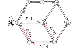
The airspace is structured similar to the roads network in the cities. Because of the characteristic of the airspace, the airlines could be as shown in Fig. 1. A general traffic network model can be formulated by using the graph theory [10]. Similar to the idea of [9], UAVs are only allowed inside the following three kinds of areas: airways which play a similar role to the roads, intersection nodes which connect at least two airways, termination nodes which connect at least one airway where UAVs fly in and out of the network.
II-B Objective
Some basic principles are provided to guide the traffic network design.
-
•
(i) Every VTOL UAV has its route.
-
•
(ii) UAVs should not collide with each other, so they should be separated at a certain distance. With such a distance , two UAVs do not need to take extra effort to avoid each other.
-
•
(iii) UAVs should not fly outside of airways.
-
•
(iv) Every UAV can have different velocities with a setting turning radius.
-
•
(v) UAVs can be allocated different priorities.
Based on these basic principles, an air traffic network, named sky highway, is designed for dense traffic. The dense traffic is denser than the current civil aviation transportation. It is similar to the traffic in highways for cars, which allows many UAVs to fly in the same airway and then to pass an intersection. Obviously, the traffic network general model shown in Fig. 1 is too abstract for the dense traffic. So, based on this general model, the objective of this paper is to further design the structure of airways and intersections and include as well their corresponding flight modes which can support dense traffic. For simplicity, only all airways and intersections on the same altitude are focused on.
III AIRWAY AND INTERSECTION DESIGN FOR DENSE TRAFFIC
In this section, the structure of airways and intersections with corresponding flight modes for supporting dense traffic are studied one by one.
III-A Airway Design and Flight Mode
III-A1 Airway Design
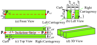
An airway is designed as shown in Fig. 2. The th airway denoted by is a set of cuboid (length width height ), which is divided into three parts, two carriageways for traffic traveling in opposite directions, namely , (length width height ), separated by an isolation strip also in the form of a cuboid, namely, (length width height ). The line segment is the center line on the middle height of the airway, where are the starting point and the ending point, respectively. So,
Airways should be designed such that two UAVs in two different carriageways are separated at a distance This implies two UAVs on two carriageways do not need to avoid with each other. Here, two different carriageways may be in one airway or two different airways. Before proceeding, the distance between two sets is defined. The distance between set and set is defined as
(a) When two different carriageways are in the same airway, the isolation strip plays an important role. A result is given in Proposition 1.
(b) When two different carriageways are in two different airways, the two airways should be separated at a distance A result is given in Proposition 2.
Proposition 2. Suppose the airway structure is shown in Fig. 2. For the th and the th airways, if
| (3) |
then
| (4) |
III-A2 Flight Mode
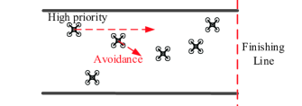
For dense traffic, a highway mode is proposed. A carriageway has several lanes but does not require UAVs on lanes one by one like trains on a railway. UAVs under decentralized control are attracted by a finishing line at the end of the airway rather than several waypoints (as shown in Fig. 4). Once approaching the finishing line, it will switch to another airway, for example, via an intersection. So, the principle (i) is satisfied. UAVs should repel each other if their distance is too short, for example, by using the artificial potential field method. Also, the curbs (as shown in Fig. 2) are required to repel UAVs to keep them within the carriageway. So principles (ii) and (iii) are satisfied. If UAVs have different velocities, then the fast UAV and the slow UAV will interact with each other according to a certain protocol. For example, a protocol is based on the artificial potential field method. Then the fast UAV and slow UAV will often change their flight directions rather than only slow down the fast one. Generally, the fast one will overtake the slow one. Then, principle (iv) is satisfied. If a UAV with a high priority has to overtake the slow UAV, then the UAV with a high priority can keep the same velocity, but the UAVs with lower priorities should make avoidance.
The highway mode is suitable for dense traffic for the following reasons. (i) The airspace is utilized sufficiently. (ii) Existent finishing line will avoid the traffic jam at the end of the airway because the velocities of UAVs are aligned like birds flying in the sky [15]. (iii) In order to perform overtaking, the fast one can often frequently change its direction a little bit to avoid the slow one rather than only reduce its speed.
III-B Intersection Design and Flight Mode
III-B1 Intersection Classification
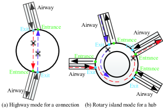
An intersection connects at least two airways. As shown in Fig. 5, there are two cases.
-
•
(i) An intersection, called a connection or azimuth connection, is connected with two airways to change azimuth, because only all airways and intersections on the same altitude are focused on. For example, Nodes are shown in Fig. 1.
- •
In the following, some basic principles on intersections are described. Furthermore, two modes for the two types of intersections are proposed.
III-B2 Intersection Design
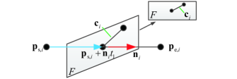
For the th intersection, as shown in Fig. 6, suppose the center lines of airways intersect at a point namely
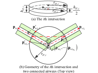
where is the index of airways. The intersection is denoted by which is a set of a cylinder with center radius and height We hope that the minimum distance between any pair of airways outside of an intersection should be greater than . Moreover, the turning radius for all UAVs is For the th and the th airways, the requirement can be formulated as
| (7) |
where
and is the complementary set of For hub intersections and connections, we have the result shown in Proposition 3.
Proposition 3. For the th intersection , line segments are parallel to the level ground and at the same altitude, . If the intersection radius satisfies
| (8) |
then (7) holds and the turning radius is satisfied, where
| (9) | ||||
| (10) |
Proof. Without loss of generality, we take and as an example. As shown in Fig. 6, are all on the middle level plane containing First, the th and th airways can be divided into two parts as
Obviously, and Since
| (11) |
the inequality
| (12) |
implies
| (13) |
Based on this, we focus on the proof of the condition (12). According to Proposition 2, we can conclude this proof.
III-B3 Highway Mode for a Connection
It can be considered that two carriageways for traffic traveling in opposite directions are established in connection. So, basic principles are satisfied in the connection. Similarly, as shown in Fig. 5(a), all UAVs fly towards their next airways in the highway mode. For example, as shown in Fig. 7, we hope that the minimum distance between any pair of UAVs inside of an intersection should be separated at . Let and be the intersection points of the intersection and the isolation strip of the th airway on the middle level plane containing , . Obviously, the distance between line segment and line segment is the minimum distance for any pair of UAVs from two different carriageways inside an intersection. If such a distance is greater than then the distance between any pair of UAVs from two different carriageways inside an intersection is greater than The result is given in Proposition 4.
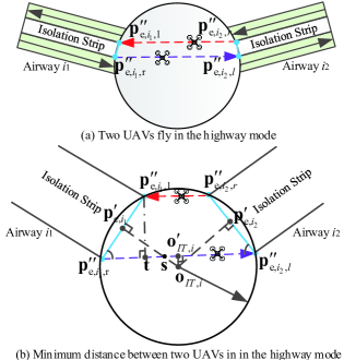
III-B4 Rotary Island Mode for a Hub
A rotary island as shown in Fig. 5(b) can be considered as a bended carriageway. In the rotary island mode, all UAVs entering the intersection will perform a clockwise or anticlockwise rotation until they fly at the entrance to the next airway. Other operations are similar to those in the highway mode. Hence, basic principles can be satisfied in a hub. One intersection can take several UAVs in it at the same time. Applying the highway mode to a hub directly will cause the jam problem because of the difference among the flight directions of UAVs in hub. In the rotary island mode, the velocity of a UAV aligns with those around it, which is similar to the situation of birds flying in the sky. It allows more UAVs in the hub simultaneously, in addition to make it easier to avoid jam.
IV EXPERIMENTS AND RESULTS
We design a set of experiments to demonstrate the effectiveness of the designed sky highway above. The video is available at https://youtu.be/WDhNroCMD04.
IV-A Simulation Experiment
Controller design is based on Matlab R2017b and Simulink 9.3, which is used for generating speed command of every UAV based on the artificial potential field method [16]. The model simulator configures parameters of UAVs, and generate sensor data to the controller via UDP communication network. The 3D viewer is based on Unreal Engine 4, which is used for displaying the real-time flight performance with high-quality screens.
Build a traffic network shown in Fig. 8, assuming that m, m. There are eighty UAVs with different routes and colors. Each UAV is required to depart from its airport and then pass the nodes in its route according to its specified sequence. During the whole process, UAVs are only permitted to fly within airways.
As shown in Fig. 8, the airways and intersections are designed within the geometrical structure of the sky highway generation module. The width of each isolation strip satisfies conditions (1) and (3), and airways connected with azimuth connections satisfy the condition (14). In addition, each intersection radius satisfies the condition (8). As shown in Fig. 8(a), we track UAVs labeled blue color. UAVs in blue and green all enter Node and leave through different carriageways. They perform a clockwise rotation in rotary island mode so that the UAV traffic flow can be increased greatly. As shown in Fig. 8(b), UAVs in blue enter the carriageway connecting Node to Node in the highway mode. Unlike in line, some UAVs fly neck by neck, so the airspace is utilized sufficiently in the carriageway. Meanwhile, UAVs in blue do not affect the UAVs in yellow on the other carriageway in the same airway because of the isolation strip. Finally, all UAVs complete their routes, and they always keep a safe distance from others as shown in Fig. 9.
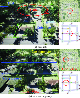
IV-B Flight Experiment
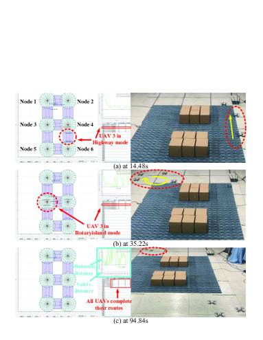
An experiment is carried out in a laboratory room with an OptiTrack motion capture system installed, which provides the ground truth of the positions and orientations of UAVs. The laptop mainly includes four modules: the geometrical structure of the sky highway generation, flight mode switching, plotting and UAV control. Build a traffic network shown in Fig. 10, assuming that m, m, m, m, m, m, m, m. Add Node and Node connected with Node and Node as airports with m and m, respectively. There are six UAVs with different routes and colors.
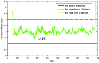
We track UAV by the dotted circle as shown in Fig. 10(a). After take-off, it enters carriageway connecting Node to Node in the highway mode at 14.48 second. As shown in Fig. 10(b), Node is a hub, and UAVs , and also enter this intersection at 35.22 second. They all perform a clockwise rotation in rotary island mode. Finally, all UAVs complete their routes at 94.84 second, and they always keep a safe distance from others as shown in Fig. 10(c).
V CONCLUSIONS
The geometrical structures of airways and intersections are designed to maintain a certain distance between two UAVs on two carriageways. For the situation that two carriageway in one airway, condition (1) has to be satisfied while for the situation that two carriageways in two airways, condition (3) has to be satisfied. The highway mode is applied to airways for dense traffic. As more than one airways will be connected with one intersection, the radius of the intersection should be large enough so that two airways outside of the intersection can keep a specified distance. For a hub or a connection, condition (8) has to be satisfied. For dense traffic, the proposed highway mode is applied to connection intersections while the proposed rotary island mode is for hub intersections. Finally, the effectiveness of the proposed sky highway is shown by the given demonstration.
References
- [1] K. Balakrishnan, J. Polastre, J. Mooberry, R. Golding and P. Sachs, Premiering a future blueprint for our sky, available at https://www.utmblueprint.com, February 28, 2019.
- [2] NASA, UAS Traffic Management (UTM), available at https://utm.arc.nasa.gov, February 28, 2019.
- [3] SESAR, European Drones Outlook 2016, available at https://www.sesarju.eu/sites/default/files/documents/reports/European DronesOutlookStudy2016.pdf, February 28, 2019.
- [4] RTCA, Final report of the RTCA Task Force 3, free flight implementation, RTCA, Inc., Washington, DC, Oct 26, 1995
- [5] J. Kosecka, C. Tomlin, G. Pappas, et al, Generation of conflict resolution maneuvers for air traffic management, International Conference on Intelligent Robots and Systems (IROS), 1997, pp 1598-1603.
- [6] ICAO, The use of displayed ADS-B data for a collision avoidance capability in unmanned aircraft system, UASSG/9-SN, no. 5, 2012.
- [7] S. Hayat, E. Yanmaz and R. Muzaffar, Survey on unmanned aerial vehicle networks for civil applications: A communications viewpoint, IEEE Communications Surveys & Tutorials, vol. 18, no. 4, 2016, pp 2624-2661.
- [8] GSMA, Mobile-enabled unmanned aircraft, available at https://www.gsma.com/iot/wp-content/uploads/2018/02/Mobile-Enabled-Unmanned-Aircraft-web.pdf, February 28, 2019.
- [9] M. Gharibi, R. Boutaba and S. L. Waslander, Internet of Drones, IEEE Access, vol. 4, 2016, pp 1148-1162.
- [10] S. Devasia and A. Lee, A scalable low-cost-UAV traffic network (uNet), Journal of Air Transportation, vol. 24, no. 3, 2016, pp 74-83.
- [11] A. Mcfadyen and T. Bruggemann, Unmanned air traffic network design concepts, 2017 IEEE 20th International Conference on Intelligent Transportation Systems (ITSC), 2017, pp 1-7.
- [12] C. Virágh, M. Nagy, C. Gershenson and G. Vásárhelyi, Self-organized UAV traffic in realistic environments, 2016 IEEE/RSJ international conference on intelligent robots and systems (IROS), 2016, pp 1645-1652.
- [13] B. Balázs and G. Vásárhelyi, Coordinated dense aerial traffic with self-driving drones, 2018 IEEE International Conference on Robotics and Automation (ICRA), 2018, pp 6365-6372.
- [14] S. J. Chung, A. A. Paranjape, P. Dames, S. Shen and V. Kumar, A survey on aerial swarm robotics, IEEE Transactions on Robotics, vol. 34, no. 4, 2018, pp. 837-855.
- [15] K. Dutta, How birds fly together: The dynamics of flocking, Resonance, vol. 15, no. 12, 2010, pp. 1097-1110.
- [16] Quan Q, Introduction to Multicopter Design and Control. Singapore: Springer Singapore, 2017.