HARQ in Full-Duplex Relay-Assisted Transmissions for URLLC
Abstract
The Release 16 completion unlocks the road to an exciting phase pertain to the sixth generation (6G) era. Meanwhile, to sustain far-reaching applications with unprecedented challenges in terms of latency and reliability, much interest is already getting intensified toward physical layer specifications of 6G. In support of this vision, this work exhibits the forward-looking perception of full-duplex (FD) cooperative relaying in support of upcoming generations and adopts as a mean concern the critical contribution of hybrid automatic repeat request (HARQ) mechanism to ultra-reliable and low-latency communication (URLLC). Indeed, the HARQ roundtrip time (RTT) is known to include basic physical delays that may cause the HARQ abandonment for the 1 ms latency use case of URLLC. Taking up these challenges, this article proposes a hybrid FD amplify-and-forward (AF)-selective decode-and-forward (SDF) relay-based system for URLLC. Over this build system, two HARQ procedures within which the HARQ RTT is shortened, are suggested to face latency and reliability issues, namely, the conventional and the enhanced HARQ procedures. We develop then an analytical framework of this relay based HARQ system within its different procedures. Finally, using Monte-Carlo simulations, we confirm the theoretical results and compare the proposed relay-assisted HARQ procedures to the source-to-destination (S2D) HARQ-based system where no relay assists the communication between the source and the destination.
Index Terms:
Cooperative relay communication, sixth generation, hybrid automatic repeat request, roundtrip time, low latency communication, outage probability.I INTRODUCTION
Ultra-reliable and low-latency communication (URLLC) is one of fifth generation (5G) driven use cases, for which the third partnership project (3GPP) and the International Mobile Telecommunications 2020 and beyond (IMT-2020) specified stringent latency and reliability requirements to fulfill. The 3GPP Rel. 14 has defined these requirements to at most 1 ms latency with an outage probability of less than for a 32 byte packet [1, 2]. In fact, the set of URLLC services with these demanding requirements in the real world, is inappropriate with the best effort manner of long term evolution (LTE) [3]. To this end, the 5G New Radio (NR) has been standardized with a set of specifications in Rel. 15, which incorporates basic URLLC features. Indeed, the NR covers implicitly the air interface latency aspect by the considered 5G numerology, however, it is not developed enough to fully achieve the required latencies. In fact, still the retransmission process across the air-interface unclear, in particular, the hybrid automatic repeat request (HARQ) roundtrip time (RTT) which has to be shortened to fit in the assumed 1 ms latency budget. Otherwise, the contribution of HARQ to URLLC is too critical and might be then, limited [4]. However, recently, as part of Rel. 16, different areas of improvements have been specified for the NR URLLC foundation. One of these enhancements focused on the uplink control information (UCI), eventually, the HARQ feedback. In fact, the main purpose is to enable the NR support for applications with latency requirements in the range of 0.5 to 1 ms and where network reliability is critical [5]. Along with this, other technological capabilities have been included to enable real-time situations, namely, the sidelink concept specifically for cellular-vehicle-to-everything (C-V2X) communications and integrated access backhaul (IAB) that points out mainly the relay concept upon 3GPP NR. Yet, several extensions will be supported by a Rel. 17 work item in order to bring several IAB improvements in terms of spectral efficiency (SE), latency, and performance. In other words Rel. 17 will rejuvenate the interest toward full-duplex (FD) transmission mode by proposing a multiplexing option for transmissions between the backhaul and access links, referred as, IAB-node full-duplex [6]. These changes mark undeniably the dawn of 6G era toward which the rich theory of FD cooperative communications is getting unleashed to aid the full sustainability of the next generation driving use cases with stringent requirements in terms of latency and reliability [7].
Cooperative relaying and FD radio communication have been extensively identified as a promising network technology to improve wireless communications reliability. In other words, as the capacity improvement is promoted by the SE improvement, the adoption of FD communication at the relay node is more advantageous and efficient. Meanwhile, thanks to recent advances noted in antenna technology and signal processing techniques, it is practical to use the FD communication mode on cooperative relaying systems even with the presence of a significant loop interference [8, 9, 10]. Furthermore, in the perspective of a low latency, FD relaying mode allows fast device-to-device discovery, and hence, contributes on the delay reduction. Accordingly, all these practical growth have incited authors to adopt FD communications in their researches, thus, get rid of the spectral inefficiency caused by half-duplex (HD) relaying mode [11, 12].
Likewise, cooperative relay communications have been always the focus of several works in the literature. Nevertheless, to the best of our knowledge their full-fledged implementation has never occurred. Indeed, the relaying concept has been introduced in 3GPP Rel. 10 as a part of LTE-Advanced, and currently, it get covered again in some study item (SI) proposals for the NR 3GPP rel. 17, specifically, pertain to SL and IAB concepts [6, 13]. In fact, relay nodes were formerly, used for the coverage extension purpose, i.e., the in-coverage user equipment (UE) assists the communication between an evolved node B (eNB) and an out-of-coverage UE [14], there is no combining of signals. Yet recently, cooperative relaying recurs intensively in the literature with great interest for competitive edge of wireless networks while targeting far-reaching use cases [15, 12, 16, 17, 18, 19, 20, 21, 22]. In support of this vision and combined with HARQ, cooperative relaying can substantially improve the system reliability and thus aid upgrading the new functions of Rel. 16 [23]. Packet retransmission in a cooperative network involves a source terminal, a destination terminal and at least one relay terminal, and it consists on recovering corrupted data packets from neighboring nodes. In other words, if the destination fails to decode the received signal, it requests the retransmission of the packet from neighboring nodes, i.e., relays, rather than asking the source node. This provides the system with a spatial diversity gain since the receiver obtains multiple copies of the same packet on channels experiencing independent fading. Therefore, link reliability as well as overall throughput can be improved.
However, when adopting cooperative relay communications, a drastic change will affect the communication latency which may bring further challenges to establish a successful quasi-real time radio communication. Generally, the supplementary latency due to relaying depends mainly on the investigated relaying technique. These techniques can be classified into regenerative and non-regenerative classes, among which we distinct respectively, the most commonly used selective decode and forward (SDF) and amplify-and-forward (AF) [24, 25]. In order to recognize the impact of the relay processing delay on the system latency, an exhaustive comparison between AF and SDF techniques under the framework of full-duplex (FD) relaying has been conducted in [26]. Simulations results proved that the SDF block-based transmission scheme is no longer practical to adopt for FD signal-combining mode, where direct and relay links are combined at the receiver side, especially, with the extra latency induced due to the complexity of encoding and decoding algorithms. Still the AF scheme represents better choice in terms of outage performance and latency.
In the literature, HARQ and relaying have been studied extensively. In [27], authors have investigated the performance of relay networks in the presence of HARQ feedback and adaptive power allocation. The throughput and the outage probability of different HARQ protocols were studied for independent and spatially-correlated fading channels. In [28], with the joint optimization of transmission power and rate, authors have adopted and have compared between many packet retransmissions schemes to find out the most appropriate one that yields to the best spectrum efficiency performance over multi-hop relay networks. In [29, 30], new types of ARQ based on a selective and opportunistic AF relaying method have been developed. Through simulations, authors showed that the proposed ARQ schemes are more effective for throughput enhancements, and can provide cell-edge users almost three times the throughput gain in comparison with ARQ with no relay-assisted forwarding. However, in the different mentioned studies, authors have applied some features to the existing retransmission mechanism with a specific purpose: Increasing the system reliability. However, this increase in reliability comes at the cost of higher latency at the system air-interface. In [31], authors have investigated diamond relay systems with HARQ protocol under delay constraints and have employed the effective capacity as a performance metric. However, the studied system has assumed a disconnected source and destination, which means that there is no direct link between the two nodes. In [32], authors have investigated a performance evaluation of HARQ-assisted hybrid satellite-terrestrial relay systems. They considered as a key performance metric, the delay limited throughput, then provided a convenient approach that includes different HARQ schemes, different relay protocols, and different key parameters. Authors in [33], conduct a generic analysis of HARQ with code combining (HARQ-CC) over double Rayleigh channels, which they consider as a typical framework that can be applied to scenarios pertains to urban vehicle-to-vehicle communication systems, amplify-and-forward relaying, as well as keyhole channels.
To the best of our knowledge, none of the cited works have build up or evaluated packet retransmission mechanisms relative to latency purpose under the framework of full-fledged implemented FD cooperative systems with non-negligible direct link. Motivated by this fact, and inspired by the comparative study results between FD-AF and FD-SDF relaying schemes presented in [26], we investigate a hybrid FD AF-SDF relay-based system for URLLC. The proposed hybrid relay assists the communication using the low latency FD-AF relaying scheme during the initial transmission. If the destination fails in decoding the received packet, the hybrid relay retransmits the same message but processed using SDF relaying.
The main contributions of this paper can be summarized as follows:
-
1.
From cross-layer perspective, this article points out the conflicting contribution of the HARQ mechanism for URLLC services. In this work, our main concern is to improve the system reliability while respecting the 1 ms latency budget requested by URLLC. Thereby, we propose the use of FD-AF during the first transmission which highly improves the signal quality at the destination side and thereby reduces the retransmission probability.
-
2.
For the adopted hybrid relay-assisted scheme, we propose two HARQ-based procedures aiming at keeping a trade-off between an extreme reliability and a low latency. Both of procedures were not considered before under the framework of FD cooperative systems with non-negligible direct link. We first propose the conventional HARQ procedure for a relay-based system where the retransmission of erroneous packets is taken over by the relay node. Then we focus on latency and reliability issues. So as to face the latency issue, we assume a reduced HARQ roundtrip time as well as a consecutive transmission time intervals (TTIs) assignment using multiple HARQ processes. The enhanced HARQ procedure is then proposed to deal with the reliability issue in the case of bad source-to-relay link.
-
3.
We evaluate the outage behavior of this relay based HARQ system within its different procedures. Note that the analytical development for the first transmission is similar to [26]. Thereby, this work’s main technical contribution in term of outage probability concerns the second transmission where the multiple copies of the signal (from the source and the hybrid FD AF-SDF relay) are combined coherently.
-
4.
For the purpose of reducing the latency, we assume a short TTI of 0.125 ms obtained at subcarrier spacing of 120 kHz. Then to evaluate the performance of our two proposed HARQ procedures, we investigate extensive simulation performance analysis where we include as a reference, the source-to-destination (S2D) HARQ-based system where no relay assists the communication between the source and the destination, the AF relaying scheme as the low latency relay processing scheme, and the SDF relaying scheme that requires complex encoding and decoding algorithms.
The rest of the paper is organized as follows: Section II presents the system model. In Section III, HARQ procedures are elaborated in detail. Outage probability is derived in Section IV. In Section V, numerical results are shown and discussed. The paper is concluded in Section VI.
II System Model
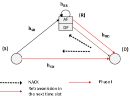
We consider a single relay cooperative system, where one relay assists the communication between a source and a destination . Since the relay operates in FD mode, we take into account the residual self-interference (RSI) generated from relay’s input to relay’s output. In this work, we assume the direct link between the source and the destination nodes is non-negligible and all channels , with and are i.i.d zero mean circularly symmetric complex Gaussian . Moreover, we assume a limited channel state information (CSI) at the source node, i.e., the source transmitter is only aware of the processing delay at the relay, and we suppose perfect CSI at the relay and the destination receivers.
The proposed HARQ-based system consists of three phases. Phase I represents the packet initial transmission where the source sends the data packet to the destination by the mean of a single relay, using FD-AF relaying. In phase II, the destination checks the correctness of the received packet and transmits either a positive or negative acknowledgment (ACK/NACK) in order to convey the success or failure of data decoding. Phase III is the packet retransmission phase activated if the destination responds with a NACK. In fact, if the destination fails in decoding a message, it stores the received signal and responds with a NACK. During the retransmission phase (Phase III), the relay resends the same message but processed using SDF relaying instead of AF relaying. At the destination, the phase I received signal is combined with phase III received signal using maximum ratio combining (MRC). In this work, we suppose perfect packet error detection and assume that the NACK feedback message is error free. Hereafter, we investigate the communication model explicitly.
During Phase I, the source first broadcasts its signal , to both the relay and destination nodes. Due to the processing delay at the relay, the destination node will receive the source node transmitted signal at different channel uses. In order to alleviate the inter-symbol interference (ISI) caused by the delayed signal, a cyclic-prefix (CP) transmission can be used at the source side [26]. Therefore, before transmitting, the source node appends a CP of length to the transmitted signal, with represents the AF processing delay at the relay. The FD relay forwards then, the amplified signal, i.e., to the destination upon the same time slot and starts the SDF processing 111The proposed FD relay decodes the received signal then reencodes it in order to retransmit it to the destination during Phase III. Note that, if the relay decoding outcome is erroneous, the relay keeps silent during the retransmission phase (Phase III)..
The received signal at the destination side, during Phase I, and after the CP removal, is expressed as
| (1) | ||||
with is the amplification constant factor chosen to satisfy the total power constraint at the relay [34], and denote, respectively, the transmit power at the source and the relay, and is the RSI after undergoing any cancellation techniques and practical isolation at the relay [8, 35]. and denote, respectively, a zero-mean complex additive white Gaussian noise at the relay and the destination. Without loss of generality, we assume that the source transmitted signals are independent .
In this paper, we assume that all channel gains change independently from one block to another and remain constant during one block of channel uses, with represents the number of transmitted codewords. Hence, we can rewrite (1) in vector form to jointly take into account the received signal as [36]
| (2) |
where , , with , with , and is a circulant matrix whose first column matrix is .
Note that the circulant matrix , can be decomposed as
| (3) |
where 222Generally, for , denotes the discrete Fourier transform (DFT) of , i.e. . is a unitary matrix whose element is , and is a diagonal matrix whose -th element is
| (4) |
The signal can be therefore represented in the frequency domain as
| (5) |
At the destination side, the instantaneous end-to-end equivalent signal-to-interference and noise ratio (SINR), during Phase I, is expressed as
| (6) | ||||
with ,
, and .
During Phase II, the destination verifies the correctness of the received data packet. If the decoding outcome is correct, the communication moves on to Phase I and starts the transmission of a new information block. When the destination fails in decoding a message, it stores the received signal and the packet retransmission phase is activated. The retransmission strategy depends on the considered HARQ procedure. In general, the received signal at the destination, during Phase III, can be expressed as
| (7) |
with
and is the retransmitter
node.
After combining the resulted copies of the same data packet at the destination using MRC technique, the instantaneous end-to-end SINR, at the destination and during Phase III is given by
| (8) | ||||
III Relay-based HARQ Procedures
The goal of this section is to propose HARQ procedures for a relay assisted system in order to improve the latency performance. For that purpose, we first present the proposed conventional HARQ procedure for a relay-based system and focus on latency and reliability issues. To face the latency issue, we assume a reduced HARQ RTT [37, 38, 39] as well as a consecutive TTI assignment using multiple HARQ processes. The enhanced HARQ procedure is then proposed to deal with the reliability issue in the case of a bad source-to-relay link.
III-A Relay-based Conventional HARQ Procedure
In the conventional system, the destination checks the correctness of the Phase I received packet and transmits either a NACK or ACK in order to convey the failure or success of data decoding. When the destination fails in decoding a message, it stores the received signal and responds with NACK. The NACK is broadcasted to both relay and source nodes, as represented in Fig. 1. While the source keeps silent, the relay retransmits the SDF processed packet. The received signal at the destination, during Phase III, is expressed as in (7) with .
III-A1 Latency Issue
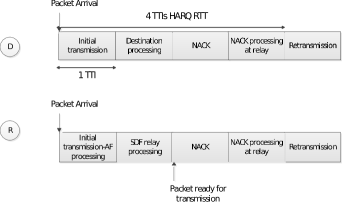
The additional delay on the transmission due to HARQ is named HARQ RTT. The HARQ RTT incorporates unavoidable physical delays, such as processing times, propagation delays, and TTI duration. In [2, 3, 40, 41, 42], it has been shown that assuming LTE-alike asynchronous HARQ operation with a minimum RTT of 8 TTIs, even with a very short TTI duration of 0.143 ms, the HARQ RTT would not satisfy the 1 ms URLLC latency target. This is the main reason of HARQ abandonment for the 1 ms end-to-end latency use case of URLLC, at least for the initial URLLC specification in Rel.15 [43]. In this work, in order to allow room for one HARQ retransmission, the reduced HARQ RTT of 4 TTIs has been adopted [40]. The proposed HARQ RTT for one FD-relay based system is presented in Fig. 2 333In this work, the propagation delay is neglected. In fact, the propagation delay depends on the distance between two nodes, however as the latter is out of the scope of this work, all nodes are supposed to have the same time offset. . We consider TTI for the initial transmission, TTI for the destination processing required to decode the initial transmission444In parellel with the destination processing, the relay performs the SDF relay processing of the received packet., TTI for the NACK feedback, and TTI for retransmitter processing of NACK.
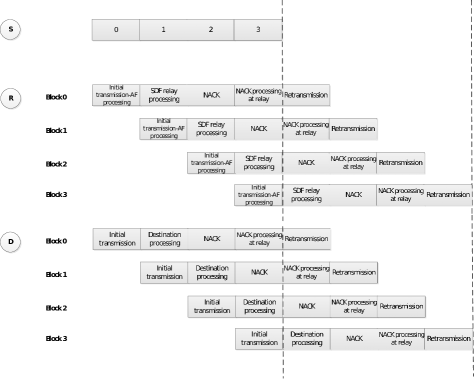
In order to allow continuous transmission while previous blocks are being decoded, four consecutive TTI assignment using multiple HARQ processes is adopted [44]. As shown in Fig. 3 555The NACK processing and the SDF processing are covered by the baseband processor (BP), while the NACK reception and the data packet transmission/retransmission are performed by the radio frequency (RF) front-end. 666The NACK processing is generally based on repetition code, whereas the SDF processing is based on LDPC or polar codes. Thereby, the NACK processing would be completed earlier than the SDF processing. , the consecutive assignment using multiple HARQ processes allows the resources to be assigned in consecutive TTIs to the same transmitting source node. At the relay and destination nodes, simultaneous HARQ processes operate in parallel to decode consecutive assignments. At the destination777The ACK/NACKs of received data packets are transmitted on a separate reverse link control channel, i.e., the NR physical uplink control channel (PUCCH), with orthogonal resources to the one in which forward link data packets are transmitted., each HARQ process is responsible for decoding one assignment, and transmitting the associated ACK or NACK TTIs after the end of that assignment. By using four consecutive TTI assignment, the system can achieve a maximum data rate that is four times greater than the non consecutive assignment if every block is decoded correctly.
III-A2 Reliability Issue
In order to achieve higher reliability, at least one retransmission is needed over a time varying channel. However, in the conventional system, presented above, the retransmission is activated only if the relay can correctly decode the received signal. In the next subsection, we propose an enhanced HARQ procedure that can solve this reliability issue.
III-B Relay-based Enhanced HARQ Procedure
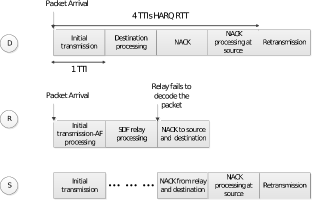
In the conventional system, presented above, the retransmission is activated only if the relay can correctly decode the received signal which reduces the relay-based HARQ system performance. To solve this problem, we propose an enhanced HARQ procedure that makes use of the modified SDF extensively studied in the literature[36, 45, 46]. In the proposed procedure, when the relay decoding outcome is erroneous, the relay broadcasts a NACK to both the destination and the source to indicate that the source will play the retransmitter role during Phase III, as shown in Fig. 4. In this enhanced procedure, the received signal at the destination, during Phase III, is expressed as
| (9) |
with
and
IV Outage Probability
In this section, we derive the outage probability of the proposed system where packet retransmission is activated only if the destination fails to decode the transmitted data packet. Note that, the system outage occurs when both transmissions, i.e., Phase I and Phase III are in outage. Therefore, the system outage probability is given by
| (10) |
where and represent
respectively, the system outage probability related to Phase I and
Phase III. Overall, to derive the system outage probability, i.e.,
, the received instantaneous SINR of ,
, and
links need to be provided. They are, respectively, given as, ,
,
and .
Note that all SINRs are exponentially distributed random variables.
Indeed, URLLC is known to cope with the finite-blocklength regime. However, for the sake of simplicity, we proceed in this study, with the case of sufficiently long codes since it has been proven to provide very close performance to the case with finite block-length [47, 48].
First, let’s derive the outage probability expression, relative to Phase I as [26]
| (11) |
with is the bit rate per channel use, the factor means that the transmission of useful codewords occupies channel uses, and represents the overall AF system average mutual information which is manipulated as below
| (12) | ||||
According to the arithmetic-geometric mean inequality, , we have . Thus, by using the first order Taylor expansion, we have Noting that , the mutual information, in (12), can be approximated as
| (13) |
Therefore, (11) can be represented as
| (14) | |||||
with is the CDF of and .
By substituting , , and links received instantaneous SINR into , we get
| (15) |
Thus, the CDF of can be derived as
| (16) |
where , , and , with , , and . Then, after some manipulations, (16) can be derived as
| (17) | ||||
Note that all integrals in (17) do not generate a closed form expression, but can be evaluated numerically using Matlab software.
The Phase III outage probability depends on the adopted HARQ procedure. In general, the can be expressed as [49]
| (18) |
where denotes, the outage probability of link, and can be expressed as
| (19) |
where . In the conventional HARQ procedure, the only retransmitter node is the relay and the retransmission happens only if the link is not in outage. Therefore, and represents the outage probability of the combined signal, i.e., Phase I and Phase III received signals, at the destination side when the relay is the retransmitter node. In the enhanced HARQ procedure, when the link is in outage, the source plays the role of the retransmitter instead of the relay during Phase III. Consequently, with represents the outage probability of the combined signal, at the destination side when the source is the retransmitter node.
In multiple HARQ processes system, when one block () is correctly decoded at the destination side, its retransmission TTI is used for the initial transmission of the next block in the buffer (). However, for the sake of simplicity, we assume that the TTI is allocated for packet retransmission even if Phase III is deactivated. Therefore, the -TTI relaying system can be viewed as a repetition coding scheme where parallel sub-channels are used to transmit symbols message [50, p.194]. The outage probability in (18) can be derived as follows
| (20) |
with is given by
| (21) |
thereby, can be derived as
| (22) |
To proceed, let’s denote . First, we have to integrate while considering as constant. Thereby, we extract limit bounds for z variable in a way to satisfy , after some manipulations we found so, the corresponding bounds, i.e., . Applying [51, 2.33.3*], we get therefore, the first integral resolution, then, we integrate the resulting expression, depending to the variable , i.e., , to get thus, the system outage probability as in (23), with and represents the imaginary error function.
| (23) | ||||
| (25) | ||||
Let’s first develop the first term in (17), , using the integration by change of variables, , while applying [51, 3.471.9], we get
| (26) |
Next, we insert (26) into (17). Then, we integrate with respect to the variable , i.e., , that shall fall within the interval defined by . We get thus, the system outage probability as in (27). With
| (27) |
V Numerical Results
In this section, the performance of the proposed relay-based HARQ procedures are studied through numerical results, and are labeled respectively as, "conventional sim" and "enhanced sim" in all figures. We used for that purpose, Monte-Carlo simulations to confirm theoretical findings derived in Section IV. We then represent the performance simulations in comparison with the two main relaying schemes with no retransmission procedure, i.e., the AF as the relaying scheme that includes a very negligibile latency and the SDF with a latency of times the transmission time interval, i.e., . We also use the S2D HARQ-based system where no relay assists the communication between the source and the destination as a reference to evaluate the performance of the proposed relay-assisted HARQ procedures 888Similar to the proposed system, in the S2D HARQ-based system, only one HARQ retransmission is allowed.. We assumed for simulation purposes, an equal power allocation among the source and the relay, i.e., , and 999To achieve a target of 1 ms latency’s requirement, we consider a frame structure for 5G NR that offers a shorten duration of the TTI. Thus according to a 3rd Generation Partnership Project 3GPP, using the scalable OFDM numerology, while assuming a subcarrier spacing of 120 KHZ [52, 53], the symbols TTI duration is .. The relay and the destination noise powers are assumed to be normalized to . For a fair comparison, we have set the sum of the transmitted power from the source and the relay nodes of the cooperative system equal to that of the non-cooperative system (S2D). We note that, , , , and stand respectively for, the source-to-destination link gain, the source-to-relay link gain, the relay-to-destination link gain, and the RSI level.
, , and negligible RSI.
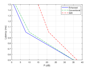
First, through Fig. 5, we assert enhancements noted with both proposed procedures in term of latency. We represent indeed, the latency level versus the transmit SNR, at a satisfied level of reliability. We compare improvements respectively between, the enhanced procedure, the conventional procedure, and the direct transmission, i.e., S2D. Note that, for the sake of clarity, results are given with a relaxed latency constraint of 1.5 ms, i.e., two allowed retransmissions. The aim is to affirm the flexibility of both procedures as they maintain their gain even with more than one retransmission. As clearly noticed, a significant enhancement is noted with what we propose, specifically, with the enhanced procedure. It is observed that the 1 ms latency constraint with a satisfied level of reliability can be achieved at less than 10 dB for the enhanced procedure whereas it requires more than 20 dB for the S2D scheme. The purpose of this work is to satisfy the 1 ms use case of URLLC, thus, all outage performance results below, are obtained on the basis of one allowed retansmission.
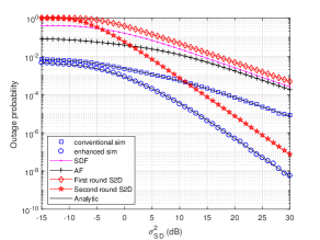
At first, we notice overall, that simulation results match perfectly
with theoretical analysis obtained in Section IV. Fig.
6
and Fig. 7, depict the
outage performance with respect to data transmission rate, . In
Fig. 6, we clearly see
that when the direct link between the source and the destination is
negligible (), the
S2D transmission fails even after two transmission rounds and using
a relay with better transmission links becomes mandatory. Due to the
SDF relaying high latency, the AF relaying offers the best performance
for one round transmissions. Using a second round transmission in
the relay-based system boosts the cooperative diversity and leads
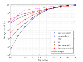
to a better performance. In Fig. 7,
we clearly see that implementing HARQ procedure in a relay based system
enhances the system outage probability from to
at . Moreover, we notice that while for low direct link gains
(), the proposed HARQ
procedures have almost similar performance, the enhanced HARQ procedure
tends to outperform the conventional one as the direct link becomes
prominent ().
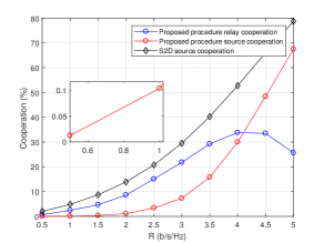
In Fig. 6 and Fig. 7, we plot the percentage of each node cooperation during the second round when the destination fails to decode the first round transmission. For S2D system, the percentage of the source cooperation during the second round is given by . For relay-assisted system, the percentage of the relay cooperation during the second round is given by while the percentage of the source cooperation during the second round for enhanced procedure is given by .
As observed from Fig. 6, in a relay-based system, the source cooperation steadily increases with the increase of transmission rate starting from zero cooperation at very low rates. On the other hand, the relay cooperation gives different performance trends. At low transmission rates, the relay cooperation increases with the increase of . After some point, it starts decreasing until it reaches zero cooperation at high rates. This is due to the fact that, at very low rates the destination can correctly decode the first round received packet. As the source increases its information rate, the first round transmission outage takes place with high probability and thereby the relay is activated to retransmit the packet. As the source further increases its rate, the link outage occurs more frequently which means that the relay becomes unable to cooperate using SDF and the system has either to keep silent during the second round when using the conventional HARQ procedure or to rely more on the source cooperation in the case of enhanced HARQ procedure. In Fig. 7, when the direct link is non negligible (), the S2D source cooperation curve during the second round has same shape as the relay-based source cooperation curve. However, thanks to the good relaying links () the relay-based system outage probability is very low during the first round compared to the S2D system and thereby the system nodes cooperation is reduced during the second round with a better outage performance.
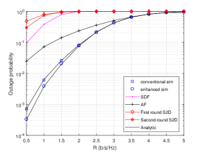
Outage probability versus .
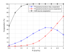
Percentage of retransmission.
, , , and .
Outage probability versus .
Percentage of retransmission.
, , , and .
We further highlight the previously mentioned conclusions from different perspectives in Fig. 8 and Fig. 9, where we investigate the outage performance respectively, according to and . Clearly Fig. 8 points out the boosting effect of the direct link gain as it tends to become gradually prominent. This favors mainly the use of a second round transmission whether over a relay-based system, i.e., enhanced HARQ or upon a S2D transmission. As can be seen, both of schemes have the same slope with a large noted diversity gain regarding the first round transmissions. However the proposed enhanced HARQ procedure still the best in term of outage performance, mainly due to the additional cooperative diversity brought through incorporating the link. Indeed, with the increase of the direct link gain, the retransmission opportunity results into more gains in terms of reliability. Specifically, this gain is exhibited through the use of the direct link that interposes to retransmit, whenever the relay is in outage.
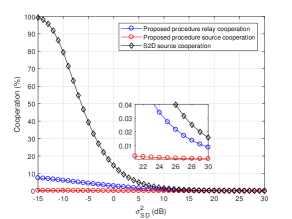
Regarding the nodes cooperation during the second round, Fig. 8, thanks to the good relaying links (), the outage event on the relay-based system is less likely to happen during the first round and thus the system nodes cooperation is reduced during the second round. More specifically, at low link gains (), once a second round transmission is required, the relay-based system will count more on the relay involvement. On the other hand, at low direct link gains, the outage probability of the S2D transmission is very high, thereby the source cooperation becomes a necessity. Then, after the sharp increase in the direct link gain, the system nodes cooperation is extremely excluded. Nevertheless, the system nodes cooperation in the relay-based system is still slightly higher than the S2D system with a very negligible gain in term of outage probability. In summary, for low link gains, the enhanced relay-based HARQ system offers the best performance with low power consumption during the second round. However, as the link becomes dominant, shutting down the relay seems to be the best solution in term of both outage performance and power consumption. For the rest of this section, we focus our analysis on low link case, i.e. .
Outage probability versus .
Percentage of retransmission.
, , and .
Now, we consider in Fig. 9, the scenario where the and the link are varying equally, and the direct link gain is brought to noise level, i.e., . As noticed, all cooperative schemes yield almost lower performance for a weak first hop link, where generally, the relay is likely to be in outage, thereby no information will successfully reach the destination by the mean of the relay. Otherwise, adopting a second round transmission for relay-based systems (conventional and enhanced HARQ procedures) offers indeed better outage performance as the and link gains become stronger. Note that whatever the first and second hop link strengths, the enhanced HARQ procedure outperforms the conventional one however, with a reduced performance gap. This happens obviously because of the non apparent use of the direct link that favors mainly the enhanced HARQ procedure. On the other hand, for one round transmissions, still AF relaying the best in term of outage performance.
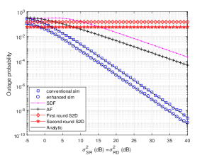
, , , and .
To evaluate the diversity order of the different schemes, we plot, in Fig. 10, Fig. 11, and Fig. 12, the outage probability versus the transmit SNR level at the source and the relay, both set to . In Fig. 10, we ignore the RSI effect at the relay for all FD relaying schemes. As shown, the first round S2D and the AF curves have the same slope indicating a unity diversity order. As expected, using a second round increases the diversity order for both direct and relay-based transmissions. Using HARQ, the S2D transmission scheme and the conventional HARQ procedure reach the same classical diversity order of . Indeed, despite the advantage of the good relaying links, the limited increase in the diversity order for the conventional procedure is mainly due to the fact that when the is in outage, the second round transmission is deactivated. On the other hand, from Fig. 10, we notice that the enhanced HARQ procedure, where the source is involved during the second round whenever the link is in outage, enjoys of a much higher diversity order of .
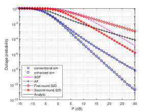
, , and negligible RSI.
In Fig. 11, we consider the case where the RSI gain in scales linearly with the relay transmit power, i.e., . We notice that all FD-relaying schemes diversity are badly affected by the loop-back interference at the relay side, i.e., the conventional HARQ procedure experiences an error floor while the enhanced HARQ procedure diversity order drops to . Still the proposed schemes offer the best performance for moderate transmit power values. However, as shown in the Fig. 12, the performance of the FD-relaying schemes can be significantly enhanced if the adopted loopback interference isolation and cancellation techniques can dramatically reduce the RSI effect, i.e., .
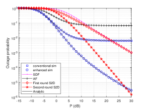
, , and .
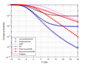
, , and .
VI Conclusion
In this paper, we investigated a hybrid FD AF-SDF relay-based system and we proposed two retransmission procedures within which the HARQ RTT is shortened as a path towards URLLC. Once a packet is received in error, the studied system might move along one of suggested retransmission procedures, namely, the conventional and the enhanced HARQ procedures. Thereby, to capture their inherent performance difference, we derived the analytical outage probability expression respectively, for the conventional and the enhanced mechanisms. Then we compared them to the most known relaying techniques, i.e., AF as the low latency relay processing scheme, and the SDF scheme that requires complex encoding and decoding algorithms. Furthermore for a fair comparison, we included the non-cooperative mode, where the direct link handles both, the transmission and the retransmission whenever a second round transmission becomes a necessity. Indeed, both of procedures allow a prompt processing, however as simulation results have revealed, the enhanced one offers additional improvements in term of reliability and eventually further available diversity via the direct link whenever the RSI is negligible.
References
- [1] 3GPP TR 38.913 V14.2.0, "Study on scenarios and requirements for next generation access technologies", (Release 14), Jun. 2016.
- [2] G. Pocovi, H. Shariatmadari, G. Berardinelli, K. Pedersen, J. Steiner, and Z. Li, "Achieving ultra-reliable low-latency communications: Challenges and envisioned system enhancements", IEEE Netw., vol. 32, no. 2, pp. 8-15, Mar./Apr. 2018.
- [3] N. Strodthoff, B. Goktepe, T. Schierl, C. Hellge, and W. Samek, "Enhanced machine learning techniques for early HARQ feedback prediction in 5G", IEEE J. Sel. Areas Commun., vol. 37, no. 11, pp. 2573-2587, Nov. 2019.
- [4] G. J. Sutton et al., "Enabling technologies for ultra-reliable and low latency communications: From PHY and MAC layer perspectives", IEEE Commun. Surveys Tuts., vol. 21, no. 3, pp. 2488-2524, Feb. 2019.
- [5] 3GPP TR 21.916 V0.5.0, "Release 16 description; Summary of rel-16 work items", Jul. 2020.
- [6] 3GPP RP-193251 “Enhancements to integrated access and backhaul” (work-item description).
- [7] A. Ghosh, A. Maeder, M. Baker, and D. Chandramouli, "5G evolution: A view on 5G cellular technology beyond 3GPP release 15", IEEE Access, vol. 7, pp. 127639-127651, Sep. 2019.
- [8] T. Riihonen, S. Werner, and R. Wichman, "Optimized gain control for single-frequency relaying with loop interference", IEEE Trans. on Wireless Commun., vol. 8, no. 6, pp. 2801-2806, Jun. 2009.
- [9] T. Kwon, S. Lim, S. Choi, and D. Hong, "Optimal duplex mode for DF relay in terms of the outage probability", IEEE Trans. Veh. Technol., vol. 57, no. 7, pp. 3628–3634, Sep. 2010.
- [10] D. Kim, H. Lee, and D. Hong, "A survey of in-band full-duplex transmission: From the perspective of PHY and MAC layers", IEEE Commun. Surveys Tuts., vol. 17, no. 4, pp. 2017–2046, Fourth Quarter Feb. 2015.
- [11] Y. Zhou, V. W. S. Wong, and R. Schober, "Stable throughput regions of opportunistic NOMA and cooperative NOMA with full-duplex relaying", IEEE Trans. on Wireless Commun., vol. 17, no. 8, pp. 5059-5075, Aug. 2018.
- [12] J. Mei, J. Zeng, X. Su, and S. Shao, "Outage performance analysis of cooperative PDMA with the full-duplex relay", in IEEE Wireless Commun. Netw. Conf. (WCNC), pp. 1-6, Marrakesh, Morocco, Apr. 2019.
- [13] 3GPP RP-193253 ”Study on NR sidelink relays” (study-item description).
- [14] S. Y. Lien, D. J. Deng, C. C. Lin, H. L. Tsai, T. Chen, C. Guo, and S. M. Cheng, "3GPP NR sidelink transmissions toward 5G V2X", IEEE Access, vol. 8, pp. 35368-35382, Feb. 2020.
- [15] G. Liu, Z. Wang, J. Hu, Z. Ding, and P. Fan, "Cooperative NOMA broadcasting/multicasting for low-latency and high-reliability 5G cellular V2X communications", IEEE Internet Things J., vol. 6, no. 5, pp. 7828-7838, Oct. 2019.
- [16] Y. Hu, M. C. Gursoy, and A. Schmeink, "Relaying-enabled ultra-reliable low-latency communications in 5G", IEEE Netw., vol. 32, no. 2, pp. 62-68, Mar./Apr. 2018.
- [17] S. Yin, Y. Zhao, L. Li, and F. R. Yu, "UAV-assisted cooperative communications with time-sharing information and power transfer", IEEE Trans. Veh. Technol., vol. 69, no. 2, pp. 1554-1567, Feb. 2020.
- [18] S. Yin, Y. Zhao, L. Li, and F. R. Yu, "UAV-assisted cooperative communications with power-splitting information and power transfer", IEEE Trans. Green Commun. Netw., vol. 3, no. 4, pp. 1044-1057, Dec. 2019.
- [19] Y. Cao, N. Zhao, G. Pan, Y. Chen, L. Fan, M. Jin, et al., "Secrecy analysis for cooperative NOMA networks with multi-antenna full-duplex relay" IEEE Trans. Commun., vol. 67, no. 8, pp. 5574-5587, Aug. 2019.
- [20] Y. Song, S. H. Lim, S. Jeon, and S. Baek, "On cooperative achievable rates of UAV assisted cellular networks", IEEE Trans. Veh. Technol., Early Access, Jun. 2020.
- [21] T. Nawaz, M. Seminara, S. Caputo, L. Mucchi, F. S. Cataliotti, and J. Catani, "IEEE 802.15.7-compliant ultra-low latency relaying VLC system for safety-critical ITS", IEEE Trans. Veh. Technol., vol. 68, no. 12, pp. 12040-12051, Dec. 2019.
- [22] G. Noh, H. Chung, and I. Kim, "Mobile relay technology for 5G", IEEE Trans. Veh. Technol., vol. 27, no. 3, pp. 6-7, Jun. 2020.
- [23] A. Ijaz, L. Zhang, A.U. Quddus, and R. Tafazolli, "HARQ in relay-assisted transmission for machine type communications", IEEE Wireless Commun. Lett., vol 5, no. 2, pp. 172-175, Jan. 2016.
- [24] F. A. Onat, H. Yanikomeroglu, and S. Periyalwar, "Relay-assisted spatial multiplexing in wireless fixed relay networks", in IEEE Global Commun. Conf. (GLOBECOM), pp. 1–6, San Francisco, CA, USA, Nov. 2006.
- [25] J. N. Laneman, D. N. C. Tse, and G. W. Wornell, "Cooperative diversity in wireless networks: Efficient protocols and outage behavior", IEEE Trans. Inform. Theory, vol. 50, no. 12, pp. 3062-3080, Dec. 2004.
- [26] FE. Airod, H. Chafnaji, and A. Tamtaoui, "A comparative study of full-duplex relaying schemes for low latency applications", Int. J. Commun. Systems, vol. 31, no. 13, e3728, Jun. 2018.
- [27] B. Makki, T. Eriksson, and T. Svensson, "On the performance of the relay-ARQ networks", IEEE Trans. Veh. Technol., vol. 65, no. 4, pp. 2078-2096, Apr. 2016.
- [28] J. Han, Y. Xi, and J. Wei, "Spectral efficient optimisation for multihop relay networks adopting HARQ schemes", Electro. Lett., vol. 53, no 5, pp. 358-360, Mar. 2017.
- [29] C-K. Tseng and S-H. Wu, "Effective protocols and channel quality control mechanisms for cooperative ARQ with opportunistic AF relaying", IEEE Trans. Veh. Technol., vol. 67, no. 3, pp. 2382-2397, Mar. 2018.
- [30] C-K. Tseng and S-H. Wu, "Selective and opportunistic AF relaying for cooperative ARQ: An MLSD perspective", IEEE Trans. Commun., vol. 67, no. 1, pp. 124-139, Jan. 2019.
- [31] D. Qiao, "Outage effective capacity of buffer-aided diamond relay systems using HARQ-IR", IEEE Trans. Veh. Technol., vol. 68, no. 1, pp. 540-553, Jan. 2019.
- [32] R. Wang, F. Zhou, J. Bian, K. An, and K. Guo, "Performance evaluation of HARQ-assisted hybrid satellite-terrestrial relay networks", IEEE Commun. Let., vol. 24, no. 2, pp. 423–427, Feb. 2020.
- [33] A. Chelli, E. Zedini, M. S. Alouini, M. Pätzold and I. Balasingham, "Throughput and delay analysis of HARQ with code combining over double Rayleigh fading channels", IEEE Trans. Veh. Technol., vol. 67, no. 5, pp. 4233-4247, May 2018.
- [34] Z. Shi, S. Ma, F. Hou, and K. W. Tam, "Analysis on full-duplex amplify-and-forward relay networks under nakagami fading channels", in IEEE Global Commun. Conf. (GLOBECOM), pp. 1-6, San Diego, CA, USA, Dec. 2015.
- [35] T. Riihonen, S. Werner, R. Wichman, and J. Hamalainen, "Outage probabilities in infrastructure-based single-frequency relay links", in IEEE Wireless Commun. Netw. Conf. (WCNC), Budapest, Hungary, pp. 1−6, Apr. 2009.
- [36] H. Chafnaji, T. Ait-Idir, H. Yanikomeroglu, and S. Saoudi, "Turbo packet combining for relaying schemes over multiantenna broadband channels", IEEE Trans. on Veh. Technol., vol. 61, no. 7, pp. 2965-2977, Sep. 2012.
- [37] M. Centenaro, D. Laselva, J. Steiner, K. Pedersen and P. Mogensen, "System-level study of data duplication enhancements for 5G downlink URLLC", IEEE Access, vol. 8, pp. 565-578, Dec. 2019.
- [38] G. Pocovi, K. I. Pedersen and P. Mogensen, "Joint link adaptation and scheduling for 5G ultra-reliable low-latency communications", IEEE Access, vol. 6, pp. 28912-28922, May. 2018.
- [39] K. Pedersen, G. Pocovi, J. Steiner and A. Maeder, "Agile 5G scheduler for improved E2E performance and flexibility for different network implementations", IEEE Commun. Mag., vol. 56, no. 3, pp. 210-217, Mar. 2018.
- [40] G. Pocovi, B. Soret, K. I. Pedersen, and P. Mogensen, "MAC layer enhancements for ultra-reliable low-latency communications in cellular networks", in IEEE Int. Conf. Commun. Workshops (ICC), pp. 1005-1010, Paris, France, May 2017.
- [41] K. I. Pedersen, S. R. Khosravirad, G. Berardinelli, and F. Frederiksen, "Rethink hybrid automatic repeat reQuest design for 5G: Five configurable enhancements", IEEE Wireless Commun., vol. 24, no. 6, pp. 154-160, Dec. 2017.
- [42] T. Fehrenbach, R. Datta, B. Goktepe, T. Wirth, and C. Hellge , "URLLC services in 5G low latency enhancements for LTE", in 88th IEEE Veh. Technol. Conf. (VTC Spring), pp. 1-6, Chicago, USA, Aug. 2018.
- [43] MCC Support, "Report of RAN1#92b v1.0.0", 3GPP, Tech. Rep.R1-1805801, pp. 127–128, Apr. 2018.
- [44] 3GPP TS 38.321 V15.5.0, “NR; Medium access control (MAC) protocol specification (Release 15), Mar. 2019.
- [45] B. Maham, A. Behnad, and M. Debbah, "Analysis of outage probability and throughput for half-duplex hybrid-ARQ relay channels", IEEE Trans. on Veh. Technol., vol. 61, no. 7, pp. 3061-3070, Sep. 2012.
- [46] M. Maaz, P. Mary, and M. Helard, "Delay outage probability in block fading channel and relay-assisted hybrid-ARQ network", IEEE Wireless Commun. Lett., vol. 3, no. 2, pp. 129-132, Apr. 2014.
- [47] B. Makki, T. Svensson, and M. Zorzi, "Finite block-length analysis of the incremental redundancy HARQ", IEEE Wireless Commun. Lett., vol. 3, no. 5, pp. 529–532, Oct. 2014.
- [48] B Makki., T. Svensson, T. Eriksson, and M. S. Alouini, "On the performance of RF-FSO links with and without hybrid ARQ", IEEE Trans. on Wireless Commun., vol. 15, no. 7, pp. 4928-4943, Jul. 2016.
- [49] F. E. Airod, H. Chafnaji, and H. Yanikomeroglu, "Performance analysis of low latency multiple full-duplex selective decode and forward relays", in IEEE Wireless Commun. Netw. Conf. (WCNC), pp. 1-6, Barcelone, Spain, Apr. 2018.
- [50] D. N. C. Tse and P. Viswanath, Fundamentals of Wireless Communications. Cambridge University Press, May 2005.
- [51] A. Jeffrey and D. Zwillinger, Table of Integrals Series and Products. San Diego, CA, USA: Academic, Mar. 2007.
- [52] A. A. Zaidi , R. Baldemair, H. Tullberg, H. Bjorkegren, L. Sundstrom, J. Medbo, and I. Da Silva, "Waveform and numerology to support 5G services and requirements", IEEE Commun. Mag., vol. 54, no. 11, pp. 90-98, Nov. 2016.
- [53] J. Sachs, G. Wikstrom, T. Dudda, R. Baldemair, and K. Kittichokechai, "5G radio network design for ultra-reliable low-latency communication", IEEE Netw., vol. 32, no. 2, pp. 24-31, Mar./Apr. 2018.