Customizing the angular memory effect for scattering media
Abstract
The memory effect in disordered systems is a key physical phenomenon that has been employed for optical imaging, metrology, and communication through opaque media. Under the conventional memory effect, when the incident beam is tilted slightly, the transmitted pattern tilts in the same direction. However, the “memory” is limited in its angular range and tilt direction. Here, we present a general approach to customize the memory effect by introducing an angular memory operator. Its eigenstates possess perfect correlation for tilt angles and directions that can be arbitrarily chosen separately for the incident and transmitted waves, and can be readily realized with wavefront shaping. This work reveals the power of wavefront shaping in creating any desired memory for applications of classical and quantum waves in complex systems.
pacs:
Valid PACS appear hereI Introduction
Multiple scattering of light in disordered media such as white paint, paper, and biological tissue randomizes the propagation of waves and scrambles the spatial information carried by an incident beam. Once the thickness of a sample exceeds the transport mean free path, the information about the incident direction is lost, and light waves are scattered in all directions. While the interference of these scattered waves forms a random grainy pattern (speckle) in transmission, some memory is retained, as a result of the deterministic scattering process Akkermans and Montambaux (2007); Berkovits and Feng (1994); Freund (1998). One prominent example is the angular memory effect: if the incident wavefront of a coherent beam is tilted by a small angle, the transmitted wavefront is tilted by the same amount in the same direction. Both classical and quantum waves possess such a memory Li and Genack (1994); Schott et al. (2015); Osnabrugge et al. (2017); Defienne et al. (2018); Lib et al. (2020), which persists even in the deep diffusive regime where forward-scattered waves are negligible and the information of the original propagation direction is lost already Freund et al. (1988); Feng et al. (1988); Berkovits et al. (1989); Freund et al. (1989). In this way the angular memory effect provides unique access to the transmitted far-field pattern behind a disordered sample, which can be conveniently scanned by tilting the incident wavefront. This feature has enabled a wide range of applications in imaging, sensing, and optical metrology through turbid media Mosk et al. (2012); Vellekoop (2015); Rotter and Gigan (2017); Yoon et al. (2020); Vellekoop and Aegerter (2010); Hsieh et al. (2010); van Putten et al. (2011); Bertolotti et al. (2012); Takasaki and Fleischer (2014); Katz et al. (2014); Yılmaz et al. (2015); Cua et al. (2017); Berto et al. (2017); Papadopoulos et al. (2017); Hofer et al. (2018); Antipa et al. (2018); Salhov et al. (2018); Stern and Katz (2019); Daniel et al. (2019).
While the angular memory effect exists for any incident wavefront, it is severely limited by the small angular range of for a diffusive sample of thickness at wavelength . Various schemes have been developed recently to increase the range of the angular memory effect, e.g., by time gating Kadobianskyi et al. (2018), spatial filtering Chen et al. (2019) of the transmitted light or disorder engineering Jang et al. (2018), as well as by combining it with the translational memory effect Osnabrugge et al. (2017); Judkewitz et al. (2015); Arruda et al. (2018) through a forward-scattering medium, or by coupling light into high-transmission eigenchannels in a diffusive medium Yılmaz et al. (2019a). What all these works have in common, however, is that they are constrained by the restrictions of the conventional memory effect for which the output wavefront tilts by the same angle and in the same direction as the input wavefront. To overcome these inherent limitations, we consider here a radical expansion of the angular memory effect by addressing the following questions: Is it possible to achieve a tilt in the output wavefront along a different direction and/or with a different angle as compared to that of the input wavefront? Can “perfect correlation” be obtained at arbitrarily chosen tilt angles which will effectively increase the memory effect range well beyond the conventional one?
The affirmative answers we provide here to these questions involve a customization of the angular memory by shaping the incident wavefront of a coherent beam. For this purpose, we introduce an angular memory operator whose eigenvectors provide perfect memory for arbitrarily chosen input and output tilt angles of the incoming and outgoing wavefronts. By launching coherent light through such an eigenvector into a diffusive system, we experimentally demonstrate that the transmitted wavefront can even tilt in the opposite direction to that of the incident wavefront. Moreover, we show that such correlations can be achieved simultaneously at different input and output angles and that the corresponding tilt angles at both the input and output may well exceed the conventional angular memory range. Our methodology is applicable to other types of memory effects and in different kinds of complex systems such as chaotic cavities or multimode fibers. It provides a general framework for designing and creating desired memories for various applications in imaging, metrology, and communication through complex media.

II Angular memory operator
To customize the angular memory effect, we first define a correlation coefficient that quantifies the similarity between a transmitted field pattern, , and one with arbitrary tilt angles of the input and output wavefronts, :
| (1) |
where denotes the input field, the field transmission matrix of the scattering medium, and are rotation operators that tilt the incoming and outgoing field profiles by angles and , respectively. See section D of the supplementary material for a detailed description of the rotation operator and how to avoid edge effects.
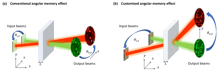
For the conventional angular memory effect the input and the output angles are equal, , and within the angular range of for a diffusive slab of thickness , as sketched in Fig. 1(a). To achieve memory for arbitrary and , we tailor the incident wavefront to maximize without compromising the overall transmittance. While nonlinear optimization methods can be employed to search for an optimal , they are unlikely to find the global maximum in such a high-dimensional search. We thus introduce here an angular memory operator whose eigenvectors maximize the correlations for any chosen input and output tilt angles. Figure 1(b) shows, as an example, that while the input wavefront is tilted in the horizontal direction, the output wavefront tilts in the vertical direction, and input and output wavefronts tilt by different angles.
To build such an angular memory operator, we start with the expression (appearing in the numerator of Eq. 1), with its eigenvectors given by . In our angular memory operator, and represent the output and input angles we choose for customizing the angular memory effect, respectively. Using these eigenvectors as input wavefronts, the numerator of the correlation coefficient in Eq. 1 equals to the corresponding complex-valued eigenvalues . Correspondingly, the eigenvectors of with large have a large numerator of . As it turns out, this does not necessarily enhance , because the eigenvectors may achieve a large numerator of already by coupling light into high-transmission eigenchannels. A higher transmission increases, however, not only the numerator, but also the denominator of without necessarily increasing the similarity between and .
To enhance instead of just its numerator, we adapt the angular memory operator in the following way:
| (2) |
The additional term counter-balances the increase of the numerator that would result from an increase in the transmittance only. Alternatively, one can also counter-balance the transmittance by using the term , which results in a similar expression in Eq. 2 (see section E in the supplementary materials for the derivation). Here, we restrict ourselves to the case where the number of output channels in the transmission matrix is no less than the number of input channels , i.e. . This situation is typically realized in experimental measurements of a transmission matrix , where the number of controlled input channels (i.e. number of columns of ) does not exceed the number of detected output channels (i.e. number of rows of ), and guarantees that the expression in Eq. 2 (left inverse of ) exists. Moreover, when the number of input and output channels is the same, , the left inverse just equals , and the angular memory operator in Eq. 2 reduces to the simple expression , with its eigenvectors satisfying . More precisely, tilted output field patterns ’s are identical to the original ones ’s, aside from a constant factor . The correlation coefficient thus reaches its maximal value, . Hence, with the number of input and output channels being equal, , the eigenvectors of , regardless of their associated eigenvalues, provide incident wavefronts to create perfectly-correlated pairs of input-output field patterns for the chosen angles and . We note that eigenvectors of a different operator were recently developed to correlate the transmitted field profile of a scattering medium to that of free space Pai et al. (2021).
When , the eigenstates of satisfy , which is to say that the outputs projected by have perfect correlation. The unprojected outputs can still exhibit high correlations, even though less than unity, and the eigenstate with the highest possible correlation will be shown below.
III Experiments
Next, we construct the angular memory operator using our experimentally-measured transmission matrix of a diffusive sample. Our sample is a densely-packed zinc oxide (ZnO) nanoparticle layer on a cover slip. The layer thickness is about 10 µm, much larger than the transport mean free path 1 µm, such that the light transport in the ZnO layer is diffusive. The transmission matrix is measured with an interferometer setup shown in Fig. S1 of the supplementary material. A linearly-polarized monochromatic laser beam at wavelength = 532 nm is split and injected into the two arms of the interferometer. A spatial light modulator (SLM) in the sample arm prepares the phase front of the light field, which is then projected onto the front surface of the ZnO layer. The light transmitted through the sample combines with the reference beam from the other arm. Their interference pattern is recorded by a CCD camera placed in the far field of the sample. The phase front of the output field from the sample is recovered from four interference patterns acquired with varying global phases displayed on the SLM. The reference beam has a flat phase front, allowing the retrieval of the relative phase between output fields at different locations in the far field. This information is critical to the construction of the angular memory operator, which requires measurement of the correlation between fields at different output angles (corresponding to different far-field locations). In contrast to the common-path interferometry method Yılmaz et al. (2019a); Popoff et al. (2010); Yılmaz et al. (2019b), which measures only the relative phases between different input channels to the same output channel (i.e., only relative phases between the columns of ), our method measures the phase differences between both columns and rows of the transmission matrix.
We construct from the measured . Experimentally we record a part of the total transmission matrix, with the number of input channels equal to the number of SLM macropixels and the number of output channels being determined by the detection area on the camera. Fig. 2 shows an example with and . Since the camera pixel size is smaller than the average speckle grain size, the number of speckle grains at the output is 455. The transverse plane - in Fig. 2 is parallel to the sample surface. We choose opposite tilts for the field profiles at the input and the output of the scattering sample, and . This means when the incoming wavefront is tilted in direction by , the outgoing wavefront tilts in by . We find the eigenvectors of such , and set the input wavefront to its first eigenvector with the largest . Because , does not reach unity, but it increases with and has the maximum at (see Fig. S3 in the supplementary material). Then we scan the tilt angle of the input wavefront along the -axis, and calculate the output wavefront using the measured transmission matrix . After tilting the output wavefront by an angle in , we calculate its correlation with the original output wavefront without tilting the input.
IV Results and discussion
Fig. 2(a) shows for each pair of and in the range of and . The conventional angular memory effect is buried in the correlation at the origin , because its range is only about and is less than the step size () of and . Therefore, the chosen angles and are well beyond the conventional angular memory effect range. Fig. 2(b) shows the output wavefront without tilting input or output, and . When the input wavefront is tilted by and output by , the output field pattern in Fig. 2(c) is very similar to the original pattern in Fig. 2(b). In contrast, the output field pattern in Fig. 2(d) is completely different for and .
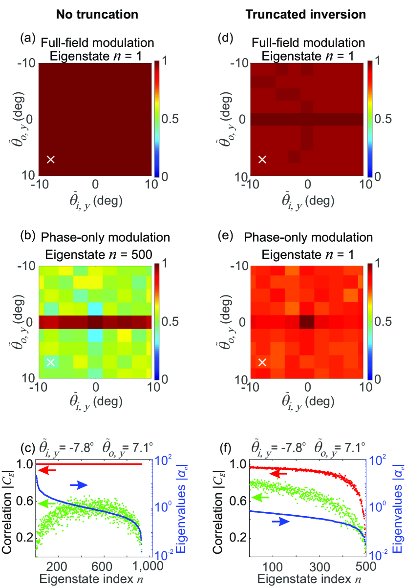
In this example (Fig. 2), the input and the output wavefronts tilt in opposite direction along axis. In Fig. S4 of the supplementary material, we present examples where the input wavefront is tilted in direction, while the output wavefront tilts in direction or in the diagonal direction . As described above, when , all eigenvectors of should achieve perfect memory with for any input and output tilt angles and . Fig. 3(a) shows that such perfect correlation is indeed observed when we reduce to . For any chosen pair of and , the corresponding 1024 eigenstates of all have , as shown in Fig. 3(c).
The full memory (perfect correlation) in Figs. 3(a,c) is obtained from an experimentally measured transmission matrix in case of full-field (amplitude and phase) modulation of the eigenvectors. However, while injecting the eigenvectors experimentally, we use an SLM that modulates only the phase of the input field. When only the phase of an eigenvector is used, however, the correlation drops significantly as shown in Fig. 3(b). This is because the eigenstates of the angular memory operator consist of both high- and low-transmission eigenchannels, and the latter are strongly affected when the amplitude modulation of the input field is removed. In Fig. 3(c), all eigenstates of have significantly less than 1 when only the phase is used. Such a dramatic reduction in due to phase-only modulation does not occur in the special case of , where the angular correlation is encoded in the input wavefront (see Fig. S8 in the supplementary material for details). To overcome the degradation at , we discard the low-transmission eigenchannels when computing the pseudo-inverse in Eq. (2), a procedure called truncated matrix inversion. In Fig. 3(d-f), among 1024 transmission eigenchannels, we keep the top 500 with high transmittance. Since the eigenstates of comprise only these 500 eigenchannels, their robustness against the absence of amplitude modulation is notably improved. In Fig. 3(d), the correlation with full-field modulation is slightly reduced because the degree of control at the input is reduced by truncated matrix inversion, but the reduction is small. In Fig. 3(f), we plot for all eigenstates of with phase-only modulation. The eigenstates with higher have stronger correlation, because they have smaller contributions from lower transmission channels, as confirmed by their transmittance shown in Fig. S5 of the supplementary material. In Fig. 3(e), the first eigenstate () with closest to 1 has above 0.73 for all input and output tilt angles and , even with phase-only modulation of its incident wavefront.
The robustness of the customized angular memory against the absence of amplitude modulation allows us to experimentally excite an eigenvector of the operator with a phase-only SLM, as shown in Fig. 4. Considering the case in Fig. 4, we display on the SLM the phase front of the first eigenstate (with the largest ) of , which is constructed with truncated matrix inversion, keeping the top 500 transmission eigenchannels out of 1024 (see section H in the supplementary material). To tilt the incident wavefront on the sample, we laterally shift the phase front on the SLM, which is at the Fourier plane of the sample front (input) surface. The step size for input angle scanning is , significantly smaller than the conventional angular memory effect range . For each tilt angle, we measure the transmitted field profile on the CCD camera with four-phase-shift interferometry. Then we tilt the transmitted wavefront and compute its correlation with the original wavefront. For comparison, we display a random phase front on the SLM to measure the conventional angular memory effect.
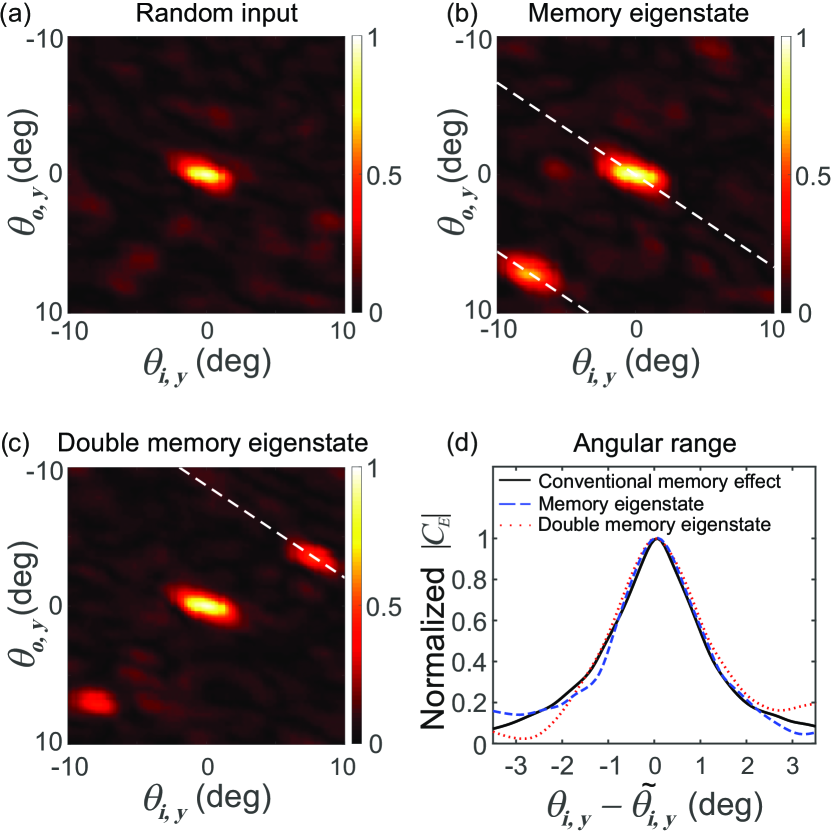
For a random input wavefront, the conventional angular memory effect manifests itself as a large correlation when and are close to 0 in Fig. 4(a). Note that the memory exists only when the shift in the incident transverse wave vector equals to the shift in the outgoing transverse wave vector. When the two sides of the medium have the same refractive index, the conventional memory effect exists along the diagonal where . In our case, the refractive index of air () above the ZnO layer is lower than that of the glass substrate () underneath the layer, so the conventional memory effect is tilted from the diagonal, and the white dashed line denotes . In addition, the unequal sampling rate of input and output tilt angles in our experiment contributes to the off-diagonal tilt, as detailed in section I of the supplementary material.
When the SLM is configured to display the input phase front of the first eigenstate of the operator, is greatly enhanced at the preselected angles and of the operator in Fig. 4(b). In spite of the phase-only modulation of input fields and a relatively large ratio , is obtained experimentally. The phase front of the incident eigenstate, displayed on the SLM, does not exhibit any spatial correlation. As shown in Fig. S8 of the supplementary material, autocorrelations of both the input and the output field patterns give sharply-peaked functions, confirming the angular correlation is not encoded at the input or the output fields. Instead, the angular memory is created via an interplay between the spatial modulation of the incident field and the deterministic scattering of light in the disordered medium. In special cases such as or , either the input or the output fields of the eigenstates of feature periodic modulations; more details about these special cases are presented in section K of the supplementary material.
Finally, to demonstrate the versatility of our approach, we create the angular memory simultaneously for two different input and output tilt angles. In order to realize this with a single incident wavefront, we construct two angular memory operators: and . Then we obtain the joint operator and find its eigenvectors with . The phase-only modulation of the input wavefront, given by the eigenvector with the highest , enhances the angular correlation at two locations far from the origin in Fig. 4(c). This means the incident wavefront has two memories: if tilted by in direction, the transmitted wavefront tilts by in ; however, if the same wavefront is tilted by in at the input, the output wavefront tilts by in instead. The correlation coefficients are reduced roughly by a factor of , compared to the case of single memory in Fig. 4(b). Such reduction is less than that of superimposing the eigenvectors of and in the incident wavefront, which would reduce the correlation approximately by a factor 2, as shown in section J of the supplementary material.
The customized memory effect holds not only at the preselected input and output angles, but also over a range around them. This behavior is similar to that of the conventional memory effect. In Fig. 4(b), with the incident wavefront equal to the first eigenvector of the angular memory operator , the correlation remains high as we scan the tilt angle of incoming wavefront around , meaning the outgoing wavefront remains nearly unchanged but tilted away from . The scanning range of the customized memory effect, given by the angular width of the normalized correlation function in Fig. 4(d), is identical to that of the conventional memory effect at the origin . Even when we simultaneously create memories at two pairs of input and output angles in Fig. 4(c), the scanning range of the memory effect at each pair is the same as that of the conventional memory effect, as shown in Fig. 4(d).
V Conclusion
In conclusion, we have introduced a general angular memory operator to customize the angular memory effect for any tilt angle of the incident and the transmitted wavefronts. As long as the number of detected output channels does not exceed that of controlled input channels, the eigenstates of exhibit perfect correlation for arbitrarily and independently chosen input and output tilt angles and directions. Experimentally, we observe strong correlations even when only the phase of the input field is modulated. Furthermore, we simultaneously create memories for different pairs of input and output tilt angles.
Although our experiment is performed on a diffusive sample with multiple scattering, our method can also be applied to a thin diffuser with forward scattering or to a multimode fiber with random mode mixing. While in the latter case the conventional angular memory effect does not even exist, our approach allows us to create any desired angular memory by launching coherent light into an eigenstate of the angular memory operator. The angular memory operator is applicable not only to classical waves, bu also to quantum waves, opening the door to customizing quantum correlations between entangled photons in complex systems Defienne et al. (2018); Lib et al. (2020). Since the memory effects exist in various domains Osnabrugge et al. (2017); Judkewitz et al. (2015); Arruda et al. (2018); Amitonova et al. (2015); Stasio et al. (2015), the angular memory operator can be extended to the translational memory operator, the rotational memory operator, etc. Our methodology generalizes the memory effects as a versatile and flexible tool for wavefront shaping applications to classical and quantum waves in complex systems.
Acknowledgments
We thank Shanti Toenger, Goëry Genty, and Arthur Goetschy for useful discussions at the initial stage of the project.
This work is supported partly by the Office of Naval Research (ONR) under Grant No. N00014-20-1-2197, and by the National Science Foundation under Grant No. DMR-1905465. M.K. and S.R. acknowledge support from the European Commission under project NHQWAVE (Grant No. MSCA-RISE 691209) and from the Austrian Science Fund (FWF) under project WAVELAND (Grant No. P32300).
The authors declare no competing interests.
References
- Akkermans and Montambaux (2007) E. Akkermans and G. Montambaux, Mesoscopic Physics of Electrons and Photons (Cambridge Univ. Press, 2007).
- Berkovits and Feng (1994) R. Berkovits and S. Feng, “Correlations in coherent multiple scattering,” Phys. Rep. 238, 135–172 (1994).
- Freund (1998) I. Freund, “‘1001’correlations in random wave fields,” Waves Random Media 8, 119–158 (1998).
- Li and Genack (1994) J. H. Li and A. Z. Genack, “Correlation in laser speckle,” Phys. Rev. E 49, 4530–4533 (1994).
- Schott et al. (2015) S. Schott, J. Bertolotti, J.-F. Léger, L. Bourdieu, and S. Gigan, “Characterization of the angular memory effect of scattered light in biological tissues,” Opt. Express 23, 13505–13516 (2015).
- Osnabrugge et al. (2017) G. Osnabrugge, R. Horstmeyer, I. N. Papadopoulos, B. Judkewitz, and I. M. Vellekoop, “Generalized optical memory effect,” Optica 4, 886–892 (2017).
- Defienne et al. (2018) H. Defienne, M. Reichert, and J. W. Fleischer, “Adaptive quantum optics with spatially entangled photon pairs,” Phys. Rev. Lett. 121, 233601 (2018).
- Lib et al. (2020) O. Lib, G. Hasson, and Y. Bromberg, “Real-time shaping of entangled photons by classical control and feedback,” Sci. Adv. 6, eabb6298 (2020).
- Freund et al. (1988) I. Freund, M. Rosenbluh, and S. Feng, “Memory effects in propagation of optical waves through disordered media,” Phys. Rev. Lett. 61, 2328–2331 (1988).
- Feng et al. (1988) S. Feng, C. Kane, P. A. Lee, and A. D. Stone, “Correlations and fluctuations of coherent wave transmission through disordered media,” Phys. Rev. Lett. 61, 834–837 (1988).
- Berkovits et al. (1989) R. Berkovits, M. Kaveh, and S. Feng, “Memory effect of waves in disordered systems: a real-space approach,” Phys. Rev. B 40, 737–740 (1989).
- Freund et al. (1989) I. Freund, M. Rosenbluh, and R. Berkovits, “Geometric scaling of the optical memory effect in coherent-wave propagation through random media,” Phys. Rev. B 39, 12403–12406 (1989).
- Mosk et al. (2012) A. P. Mosk, A. Lagendijk, G. Lerosey, and M. Fink, “Controlling waves in space and time for imaging and focusing in complex media,” Nat. Photon. 6, 283–292 (2012).
- Vellekoop (2015) I. M. Vellekoop, “Feedback-based wavefront shaping,” Opt. Express 23, 12189–12206 (2015).
- Rotter and Gigan (2017) S. Rotter and S. Gigan, “Light fields in complex media: mesoscopic scattering meets wave control,” Rev. Mod. Phys. 89, 015005 (2017).
- Yoon et al. (2020) S. Yoon, M. Kim, M. Jang, Y. Choi, W. Choi, S. Kang, and W. Choi, “Deep optical imaging within complex scattering media,” Nat. Rev. Phys. 2, 141–158 (2020).
- Vellekoop and Aegerter (2010) I. M. Vellekoop and C. Aegerter, “Scattered light fluorescence microscopy: imaging through turbid layers,” Opt. Lett. 35, 1245–1247 (2010).
- Hsieh et al. (2010) C. L. Hsieh, Y. Pu, R. Grange, G. Laporte, and D. Psaltis, “Imaging through turbid layers by scanning the phase conjugated second harmonic radiation from a nanoparticle,” Opt. Express 18, 20723–20731 (2010).
- van Putten et al. (2011) E. G. van Putten, D. Akbulut, J. Bertolotti, W. L. Vos, A. Lagendijk, and A. P. Mosk, “Scattering lens resolves sub-100 nm structures with visible light,” Phys. Rev. Lett. 106, 193905 (2011).
- Bertolotti et al. (2012) J. Bertolotti, E. G. van Putten, C. Blum, A. Lagendijk, W. L. Vos, and A. P. Mosk, “Non-invasive imaging through opaque scattering layers,” Nature 491, 232–234 (2012).
- Takasaki and Fleischer (2014) K. T. Takasaki and J. W. Fleischer, “Phase-space measurement for depth-resolved memory-effect imaging,” Opt. Express 22, 31426–31433 (2014).
- Katz et al. (2014) O. Katz, P. Heidmann, M. Fink, and S. Gigan, “Non-invasive single-shot imaging through scattering layers and around corners via speckle correlations,” Nat. Photon. 8, 784–790 (2014).
- Yılmaz et al. (2015) H. Yılmaz, E. G. van Putten, J. Bertolotti, A. Lagendijk, W. L. Vos, and A. P. Mosk, “Speckle correlation resolution enhancement of wide-field fluorescence imaging,” Optica 2, 424–429 (2015).
- Cua et al. (2017) M. Cua, E. Zhou, and C. Yang, “Imaging moving targets through scattering media,” Opt. Express 25, 3935–3945 (2017).
- Berto et al. (2017) P. Berto, H. Rigneault, and M. Guillon, “Wavefront sensing with a thin diffuser,” Opt. Lett. 42, 5117–5120 (2017).
- Papadopoulos et al. (2017) I. N. Papadopoulos, J.-S. Jouhanneau, J. F. A. Poulet, and B. Judkewitz, “Scattering compensation by focus scanning holographic aberration probing (F-SHARP),” Nat. Photon. 11, 116–123 (2017).
- Hofer et al. (2018) M. Hofer, C. Soeller, S. Brasselet, and J. Bertolotti, “Wide field fluorescence epi-microscopy behind a scattering medium enabled by speckle correlations,” Opt. Express 26, 9866–9881 (2018).
- Antipa et al. (2018) N. Antipa, G. Kuo, R. Heckel, B. Mildenhall, E. Bostan, R. Ng, and L. Waller, “DiffuserCam: lensless single-exposure 3D imaging,” Optica 5, 1–9 (2018).
- Salhov et al. (2018) O. Salhov, G. Weinberg, and O. Katz, “Depth-resolved speckle-correlations imaging through scattering layers via coherence gating,” Opt. Lett. 43, 5528–5531 (2018).
- Stern and Katz (2019) G. Stern and O. Katz, “Noninvasive focusing through scattering layers using speckle correlations,” Opt. Lett. 44, 143–146 (2019).
- Daniel et al. (2019) A. Daniel, D. Oron, and Y. Silberberg, “Light focusing through scattering media via linear fluorescence variance maximization, and its application for fluorescence imaging,” Opt. Express 27, 21778–21786 (2019).
- Kadobianskyi et al. (2018) M. Kadobianskyi, I. N. Papadopoulos, T. Chaigne, R. Horstmeyer, and B. Judkewitz, “Scattering correlations of time-gated light,” Optica 5, 389–394 (2018).
- Chen et al. (2019) M. Chen, H. Liu, Z. Liu, P. Lai, and S. Han, “Expansion of the FOV in speckle autocorrelation imaging by spatial filtering,” Opt. Lett. 44, 5997–6000 (2019).
- Jang et al. (2018) M. Jang, Y. Horie, A. Shibukawa, J. Brake, Y. Liu, S. M. Kamali, A. Arbabi, H. Ruan, A. Faraon, and C. Yang, “Wavefront shaping with disorder-engineered metasurfaces,” Nat. Photon. 12, 84–90 (2018).
- Judkewitz et al. (2015) B. Judkewitz, R. Horstmeyer, I. M. Vellekoop, I. N. Papadopoulos, and C. Yang, “Translation correlations in anisotropically scattering media,” Nat. Phys. 11, 684–689 (2015).
- Arruda et al. (2018) T. J. Arruda, A. S. Martinez, and F. A. Pinheiro, “Controlling optical memory effects in disordered media with coated metamaterials,” Phys. Rev. A 98, 043855 (2018).
- Yılmaz et al. (2019a) H. Yılmaz, C. W. Hsu, A. Goetschy, S. Bittner, S. Rotter, A. Yamilov, and H. Cao, “Angular memory effect of transmission eigenchannels,” Phys. Rev. Lett. 123, 203901 (2019a).
- Pai et al. (2021) P. Pai, J. Bosch, M. Kühmayer, S. Rotter, and A. P. Mosk, “Scattering invariant modes of light in complex media,” Nat. Photon. (2021).
- Popoff et al. (2010) S. M. Popoff, G. Lerosey, R. Carminati, M. Fink, A. C. Boccara, and S. Gigan, “Measuring the transmission matrix in optics: an approach to the study and control of light propagation in disordered media,” Phys. Rev. Lett. 104, 100601 (2010).
- Yılmaz et al. (2019b) H. Yılmaz, C. W. Hsu, A. Yamilov, and H. Cao, “Transverse localization of transmission eigenchannels,” Nat. Photon. 13, 352––358 (2019b).
- Amitonova et al. (2015) L. V. Amitonova, A. P. Mosk, and P. W. H. Pinkse, “Rotational memory effect of a multimode fiber,” Opt. Express 23, 20569–20575 (2015).
- Stasio et al. (2015) N. Stasio, D. B. Conkey, C. Moser, and D. Psaltis, “Light control in a multicore fiber using the memory effect,” Opt. Express 23, 30532–30544 (2015).