Coupling a single trapped atom to a whispering-gallery-mode microresonator
Abstract
We demonstrate trapping of a single 85Rb atom at a distance of 200 nm from the surface of a whispering-gallery-mode bottle microresonator. The atom is trapped in an optical potential, which is created by retroreflecting a red-detuned focused laser beam from the resonator surface. We counteract the trap-induced light shift of the atomic transition frequency by superposing a second laser beam with suitably chosen power and detuning. This allows us to observe a vacuum Rabi-splitting in the excitation spectrum of the coupled atom-resonator system. This first demonstration of stable and controlled interaction of a single atom with a whispering-gallery-mode in the strong coupling regime opens up the route towards the implementation of quantum protocols and applications that harvest the chiral atom-light coupling present in this class of resonators.
pacs:
Valid PACS appear hereIn free space, the interaction between single atoms and single photons is weak. However, by strongly confining the photons inside a microresonator with high quality factor, , and by coupling the atoms to the resonator mode, atom-light interaction can be significantly enhanced. This approach lies at the heart of cavity quantum electrodynamics (CQED) Thompson et al. (1992); Brune et al. (1996); Kuhn et al. (2002). Over the past decades, ultra-high finesse Fabry-Pérot microresonators have been instrumental in advancing this field. In these traditional resonators, single atoms have been trapped inside the resonator mode Ye et al. (1999); Pinkse et al. (2000), which has lead to many ground-breaking experiments Reiserer and Rempe (2015).
More recently, also other resonator types have successfully been employed in single-atom CQED, such as optical fiber-based Fabry-Pérot cavities Volz et al. (2011); Steiner et al. (2013); Gallego et al. (2018); Brekenfeld et al. (2020), photonic crystal cavities Thompson et al. (2013); Goban et al. (2015), optical nanofiber-based cavities Kato and Aoki (2015); Nayak et al. (2019), and whispering-gallery-mode (WGM) microresonators Aoki et al. (2006); Junge et al. (2013); Shomroni et al. (2014). Out of those, WGM resonators distinguish themselves by offering chiral, i.e. propagation-direction-dependent, light-matter interaction Junge et al. (2013); Lodahl et al. (2017), which enables novel protocols and functionalities for processing light on the quantum level O’Shea et al. (2013); Shomroni et al. (2014); Scheucher et al. (2016); Bechler et al. (2018). However, so far, only free-falling atoms have been coupled to WGM resonators, resulting in a limited interaction time, a position-dependent coupling strength between atom and light which reduces process fidelities, and only a probabilistic operation. In this respect, CQED with WGM resonators now stands at the point where CQED with Fabry-Pérot resonators was two decades ago, and gaining the ability to trap atoms inside the resonator field would be a crucial step forward.
Here, we demonstrate strong coupling of a single trapped rubidium atom to a WGM bottle microresonator with ultrahigh quality factor, Pöllinger et al. (2009). We achieve this by overcoming two crucial experimental challenges: First, efficient coupling to the evanescent field of the WGM requires the atom to be trapped at a small distance from the resonator surface where van der Waals- and Casimir-Polder-forces have to be counteracted. To achieve this, we employ a deep standing-wave optical dipole trap, created by retroreflecting a focused trapping light field from the resonator surface Thompson et al. (2013). Secondly, the intense light field of the trap induces a large position-dependent light-shift, which detunes the atomic resonance from the resonator mode. We effectively counteract the light shift of the atomic transition by means of a second, detuned compensation light field that shifts the excited state back into resonance Hilton et al. (2019). As a result, we observe a resonant vacuum Rabi-splitting in the excitation spectrum of the trapped atom-resonator system, indicating strong coupling.
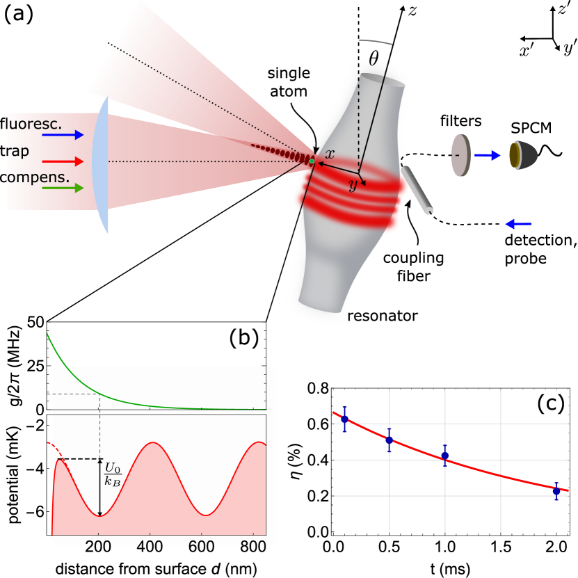
The core elements of the experimental setup are shown in Fig. 1(a). The WGM bottle microresonator features a quality factor of and is stabilized to the resonance of the unperturbed transition of 85Rb with angular frequency . In order to couple light into and out of the resonator, it is interfaced with a tapered fiber coupler. The system is set to critical coupling such that, in the absence of a coupled atom, the transmission of resonant light through the coupling fiber vanishes. This occurs when the fiber-resonator coupling rate equals the intrinsic resonator field decay rate . The total resonator field decay rate is then given by MHz, see below.
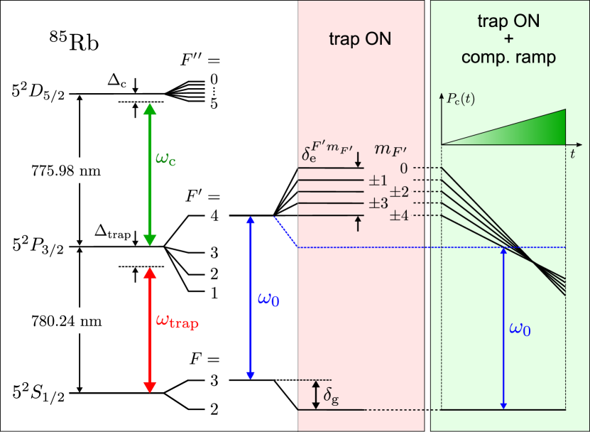
The optical dipole trap is created by retroreflecting a focused laser beam (waist radius: m) from the bottle resonator surface. The wavelength of the trapping light ( nm) is red-detuned with respect to the transition, see Fig. 2. The interference between the incident beam and its reflection forms a partially modulated standing-wave pattern along the -axis, orthogonal to the resonator axis (-axis). The incidence angle 17° with respect to the -axis prevents unwanted interference between the incident beam and its reflection from the back-surface of the resonator. Figure 1(b) shows the trap potential and the expected atom-light coupling strength as a function of the distance, , of the atom from the resonator surface in -direction. We trap a single atom in the potential minimum closest to the resonator, which is located at 205 nm. For this position, we expect an atom-light coupling strength of MHz which puts the system at the onset of strong coupling, i.e., , where MHz is the atomic dipole decay rate. For the parameters that are used in the remainder of the manuscript, the axial and transverse trap frequencies are , respectively.
The trap is loaded from a 1-cm diameter cloud of about laser-cooled 85Rb atoms that is delivered to the resonator by an atomic fountain and has a temperature of about 7 K. In order to detect the presence of a single atom in the resonator mode in real time, we send resonant detection light through the coupling fiber and monitor the transmitted power using a single-photon counting module (SPCM). The interaction of an atom with the resonator mode leads to a transmission increase, to which we react using a field programmable gate array (FPGA)-based detection and control system Junge et al. (2013). Upon detection of an atom, the detection light is switched off using an electro-optical modulator, and the dipole trap is switched on using an acousto-optical modulator. The overall delay between detection and trapping is about 250 ns. As this duration is much shorter than the average transit time of an atom through the evanescent field of the resonator mode, it allows us to catch an atom which was detected in the vicinity of the trapping potential.
In order to verify that the trap loading succeeded, we use a fluorescence detection scheme: we launch a 20 s-long detection pulse through the trap optics onto the atom. This light pulse has a center frequency of and a peak intensity of about 100 , where is the saturation intensity of the transition. A certain fraction of the fluorescence photons are scattered into the resonator mode and detected with the SPCM, see Fig. 1. This allows us to detect the presence of an atom in the dipole trap in spite of the large trap-induced detuning between the atomic resonance and the resonator. By varying the timing of the light pulse, we measure the probability for finding a single atom, which was initially detected via increased resonator transmission, at a waiting time, , after switching on the trap, see Fig. 1(c). Fitting an exponential function (red solid line) to the measured probabilities, , yields a probability for trapping a given detected single atom of % and a trap lifetime of ms. This trapping probability is compatible with our expectation considering the finite overlap of the trap volume with the resonator mode, the initial kinetic energy of the atom and the time delay between atom detection and switching on the trap.
The energy of an atom in the trap is predominantly determined by its kinetic energy and its position with respect to the trap center at the moment the dipole trap switches on. The kinetic energy is dominated by the free-fall of the atom and corresponds to mK. Consequently, trapping the atom requires an optical potential with significant depth. We use a dipole trap beam, which is linearly polarized and has a power of mW. When the trap field is polarized along the -axis (-axis), the trap depth amounts to mK , due to the polarization-dependent reflection coefficient.
The trapping light field induces a scalar light shift, , of the ground state and a scalar as well as tensor light shifts, , of the excited state, see Fig. 2. The resulting Zeeman state-dependent shifts of the transition frequencies reach up to about 250 MHz.
In order to efficiently interface the trapped atom with the resonator in the presence of this light shift, we have to compensate for the latter. For this purpose, we expose the atom to an additional light field – the so-called compensation field. Its polarization is aligned with the linear polarization of the trap field and its frequency is red-detuned by MHz with respect to the transition. The compensation field induces a scalar and tensor light shift on the excited state while its effect on the ground state is negligible. The compensation laser is offset-locked to the transition using absorption spectroscopy Kalatskiy et al. (2017), see supplementary material.
For optimal compensation of the trap-induced light shift of the transition, the relative intensity distribution of the compensation field should match as much as possible that of the trapping field. This is facilitated by the fact that the two fields have similar wavelengths ( nm and nm). In our setup, we simultaneously send them through the same fiber-coupled focusing optics, such that the positions of their foci, their waist radii, and their standing-wave patterns near the resonator closely match upon reflection off the resonator. This allows us to cancel the trap-induced scalar light shift of the transition in the entire trapping volume, when the power of the compensation field, , is adequately chosen.
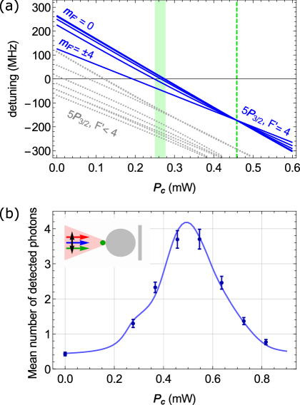
Figure 3(a) shows the calculated detunings of the two-color light shifted frequencies of the transitions between the ground state and the excited state manifold as a function of , see supplementary material. Here, we assume that the atom is located in the trap center, and we take the frequency of the cycling transition in the absence of light shifts, , as the reference. With increasing power of the compensation field, both the scalar and tensor light shifts of the transition frequencies decrease.
In the power range from mW to mW, the detuning of the transition frequencies to the () excited states sequentially cross zero, see green shaded area. However, this does not imply that light shifts are vanishing, but that the light shifts of the ground and excited states are equal, see Fig. 2. The dashed green line indicates a second interesting setting. There, the transition frequencies to the Zeeman levels of each individual -manifold intersect for the same value of . In other words, the tensor light shift of the excited state vanishes at this power and one approximately recovers the unperturbed excited state hyperfine structure, see supplementary material.
In order to experimentally find the point of optimal compensation we measure the fluorescence of a single trapped atom emitted into the resonator mode, as a function of the compensation laser power. For this purpose, we send probe light resonant with the unperturbed transition through the trap optics for 100 s and measure the intra-resonator power via the coupling fiber. In this measurement, the probe laser intensity was about 2 at the center of the trap. Figure 3(b) shows the mean number of fluorescence photons detected via the coupling fiber. The blue solid line is a theoretical fit where we calculate fluorescence spectra for transitions between all Zeeman levels of the and manifolds including the position-dependent light shifts from the trap and the compensation laser fields, see supplementary material. Moreover, we expect that, because of chromatic aberrations of our trap optics the foci of the two beams are displaced with respect to each other along the beam axis. This results in a mismatch of the radii of the trapping and compensation laser beams at the position of the atom. We average the calculated spectra over the position distribution of the atoms in the trap, which we estimate from an independent temperature measurement, see supplementary material. We fit this average spectrum to the data using as fit parameters the beam radius mismatch, the maximum mean number of detected photons and the polarization ellipticity introduced from birefringence of the optical components. This fit yields a ratio of the beam radii of and a reduced overlap with linear polarization of about 96 %. Both values are reasonable for our experimental setup and the agreement between the theoretical fit and the experimental data is very good. The maximum scattering rate is found for a compensation laser power of W.
We now measure spectra of the coupled atom-resonator system for different compensation laser powers, . Here, we align the linear polarizations of the dipole trap and of the compensation light along the -axis. With respect to this axis, the transverse-magnetic WGMs are approximately - or -polarized and, thus, couple to the cycling transition.
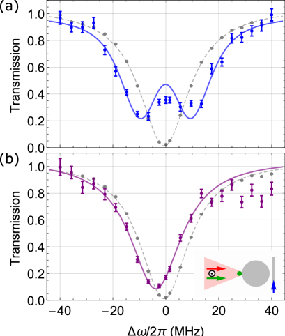
We launch probe light through the coupling fiber and vary its detuning . For each value of , we record the transmission, which is averaged over s. Figure 4(a) shows the most symmetric spectrum, which we obtained for W. It exhibits a vacuum Rabi-splitting corresponding to an atom-photon coupling strength of about MHz, in agreement with our expectations, see Fig. 1(b). This demonstrates, for the first time, strong coupling of a single trapped atom to a WGM resonator. We note that, in addition to compensating the mean light shift of the atomic transition, the light shift compensation also reduces the substantial broadening of the atomic transition frequency and the concurrent blurring of the Rabi splitting due to the atomic motion in the trap. For comparison, Fig. 4(b) shows the transmission spectrum in the absence of light shift compensation. In this case, due to the large atom-resonator detunings, we only observe a small dispersive shift of the resonator resonance. The spectra for the other values of are shown in the supplementary material.
The solid line in Fig. 4(a) is the theoretical prediction of the vacuum Rabi spectrum for a compensation laser power of W, where the spectrum turns out to be most symmetric. It was obtained by averaging vacuum Rabi spectra over different atom-photon coupling strengths and light shifts for the same position distribution and beam radius mismatch as the ones used for analysing Fig. 3(b). The resulting average coupling strength is MHz with a standard deviation of MHz. We note that, even though the experimentally determined value for is % larger, a symmetric vacuum Rabi spectrum for around 400 W is indeed expected when consulting Fig. 3 (a). In measuring , transitions between all magnetic sublevels of the and hyperfine manifolds contribute to the signal. For the measurement of the Rabi spectrum, however, we predominantly drive the cycling transition. As shown in panel (a), the latter features a smaller light shift, which is already compensated for a laser power of . Still, there is a 17 % discrepancy between the compensation laser powers for which we obtain a symmetric vacuum Rabi spectrum in the experiment ( W) and in the theoretical model ( W). We mostly attribute this to the % error in determining from Fig. 3(b). This error impacts our estimation of the ratio of the compensation and trap laser beam radii, , which enters as a parameter in our theoretical model.
In summary, we optically trapped a single atom at a distance of about 200 nm from the surface of a WGM microresonator and compensated the position-dependent trap-induced light shift of the atomic transition. This allowed us to demonstrate stable and controlled interaction of a single atom with a whispering-gallery-mode in the strong coupling regime, thereby overcoming a long-standing challenge of optical cavity quantum electrodynamics. The demonstrated method can also be applied to WGM and ring resonators on integrated optical chips. This lays the pathway towards realizing more complex quantum-controlled photonic circuits, which may in particular profit from the chiral nature of atom-light coupling in this setting.
We thank Adèle Hilico for her contributions in the early stages of the experiment. This work was financially supported by the Austrian Science Fund (FWF; SFB FoQuS Project No. F 4017 and DK CoQuS Project No. W 1210-N16), the Alexander von Humboldt-Foundation (Alexander von Humboldt Professorship).
References
- Thompson et al. (1992) R. Thompson, G. Rempe, and H. Kimble, Physical Review Letters 68, 1132 (1992).
- Brune et al. (1996) M. Brune, F. Schmidt-Kaler, A. Maali, J. Dreyer, E. Hagley, J. Raimond, and S. Haroche, Physical Review Letters 76, 1800 (1996).
- Kuhn et al. (2002) A. Kuhn, M. Hennrich, and G. Rempe, Physical Review Letters 89, 067901 (2002).
- Ye et al. (1999) J. Ye, D. Vernooy, and H. Kimble, Physical Review Letters 83, 4987 (1999).
- Pinkse et al. (2000) P. Pinkse, T. Fischer, P. Maunz, and G. Rempe, Nature 404, 365 (2000).
- Reiserer and Rempe (2015) A. Reiserer and G. Rempe, Reviews of Modern Physics 87, 1379 (2015).
- Volz et al. (2011) J. Volz, R. Gehr, G. Dubois, J. Estève, and J. Reichel, Nature 475, 210 (2011).
- Steiner et al. (2013) M. Steiner, H. M. Meyer, C. Deutsch, J. Reichel, and M. Köhl, Physical Review Letters 110, 043003 (2013).
- Gallego et al. (2018) J. Gallego, W. Alt, T. Macha, M. Martinez-Dorantes, D. Pandey, and D. Meschede, Physical Review Letters 121, 173603 (2018).
- Brekenfeld et al. (2020) M. Brekenfeld, D. Niemietz, J. D. Christesen, and G. Rempe, Nature Physics , 1 (2020).
- Thompson et al. (2013) J. D. Thompson, T. Tiecke, N. P. de Leon, J. Feist, A. Akimov, M. Gullans, A. S. Zibrov, V. Vuletić, and M. D. Lukin, Science 340, 1202 (2013).
- Goban et al. (2015) A. Goban, C.-L. Hung, J. Hood, S.-P. Yu, J. Muniz, O. Painter, and H. Kimble, Physical Review Letters 115, 063601 (2015).
- Kato and Aoki (2015) S. Kato and T. Aoki, Physical Review Letters 115, 093603 (2015).
- Nayak et al. (2019) K. P. Nayak, J. Wang, and J. Keloth, Physical Review Letters 123, 213602 (2019).
- Aoki et al. (2006) T. Aoki, B. Dayan, E. Wilcut, W. P. Bowen, A. S. Parkins, T. Kippenberg, K. Vahala, and H. Kimble, Nature 443, 671 (2006).
- Junge et al. (2013) C. Junge, D. O’Shea, J. Volz, and A. Rauschenbeutel, Physical Review Letters 110, 213604 (2013).
- Shomroni et al. (2014) I. Shomroni, S. Rosenblum, Y. Lovsky, O. Bechler, G. Guendelman, and B. Dayan, Science 345, 903 (2014).
- Lodahl et al. (2017) P. Lodahl, S. Mahmoodian, S. Stobbe, A. Rauschenbeutel, P. Schneeweiss, J. Volz, H. Pichler, and P. Zoller, Nature 541, 473 (2017).
- O’Shea et al. (2013) D. O’Shea, C. Junge, J. Volz, and A. Rauschenbeutel, Physical Review Letters 111, 193601 (2013).
- Scheucher et al. (2016) M. Scheucher, A. Hilico, E. Will, J. Volz, and A. Rauschenbeutel, Science 354, 1577 (2016).
- Bechler et al. (2018) O. Bechler, A. Borne, S. Rosenblum, G. Guendelman, O. E. Mor, et al., Nature Physics 14, 996 (2018).
- Pöllinger et al. (2009) M. Pöllinger, D. O’Shea, F. Warken, and A. Rauschenbeutel, Physical Review Letters 103, 053901 (2009).
- Hilton et al. (2019) A. P. Hilton, C. Perrella, A. N. Luiten, and P. S. Light, Physical Review Applied 11, 024065 (2019).
- Kalatskiy et al. (2017) A. Y. Kalatskiy, A. Afanasiev, P. Melentiev, and V. Balykin, Laser Physics 27, 055703 (2017).