Worrakitpoonpon
Tirawut Worrakitpoonpon, Suranaree University of Technology, Nakhon Ratchasima 30000, Thailand
Formation of spiral structure from the violent relaxation of self-gravitating disks
Abstract
We present the numerical study of the formation of spiral structure in the context of violent relaxation. Initial conditions are the out-of-equilibrium disks of self-gravitating particles in rigid rotation. By that mechanism, robust and non-stationary spiral arms can be formed within a few free-fall times by the shearing of the mass ejection following the collapse. With a closer look, we find different properties of the arms in connection with the initial configuration. The winding degree tends to increase with initial angular speed provided that a disk is thin. If disk surface is circular, both number and position of arms are governed by the Poissonian density fluctuations that produce more arms as more particles are introduced. On the contrary, if the surface ellipticity is imposed, the number of arms and their placement are effectively controlled. Otherwise, the increase of thickness leads to a complicated outcome since the number of arms and winding degree are less effectively controlled. We speculate that this complexity is caused by a strong non-axisymmetric field during the violent relaxation that disorganizes the pre-collapse motion and the concentration of particles.
keywords:
gravitation, methods: numerical, galaxies: spiral1 Introduction
The fact that a system governed by self-gravity, or more generally the long-range interaction, starting far from equilibrium undergoes the violent relaxation leading to the quasi-stationary state (QSS) has been established as a standard paradigm in the field of non-equilibrium statistical mechanics. This theory has been proposed by Lynden-Bell (\APACyear1967) in attempt to resolve the deviation of the observed light distribution of elliptical galaxies from the isothermal profile. His work demonstrates that, under the time-varying mean-field created during this stage, the system relaxes to a predictable QSS within a time-scale of order dynamical times. In the following years, the discrepancy arises because numerous simulations reveal that there does not exist the universal QSS as proposed by the Lynden-Bell theory. The relaxed states exhibit great diversities of density profiles and the velocity distributions and almost all of them can not be described by the Lynden-Bell statistics (see, e.g., Aguilar \BBA Merritt \APACyear1990; Roy \BBA Perez \APACyear2004; Trenti \BOthers. \APACyear2005; Boily \BBA Athanassoula \APACyear2006; Barnes \BOthers. \APACyear2009; Sylos Labini \APACyear2013). Only when the relaxation is not too violent, the Lynden-Bell distribution fits the QSS (Levin \BOthers., \APACyear2008). In addition, the violent relaxation of a rotating spheroid has also been examined to explain the highly flattened configuration of the elliptical galaxies (Gott, \APACyear1973; Aguilar \BBA Merritt, \APACyear1990; Katz, \APACyear1991).
While the majority of studies addresses principally to the ellipticity and the density profile of the QSS, a recent work by Benhaiem \BOthers. (\APACyear2017) proposes that the formation of long-lived non-stationary spiral structure by the violent relaxation is possible if one starts from gravitationally unstable rotating ellipsoids. This provides an alternative scenario different from the standard framework of this issue which believes that the spiral pattern is the perturbed component of the disk or bulge in equilibrium (Lin \BBA Shu, \APACyear1964; Goldreich \BBA Lynden-Bell, \APACyear1965) or the tidal tails by the passage of a companion object (Toomre \BBA Toomre, \APACyear1972). Following work of the same group explores further and demonstrates that some specific structures such as bar and ring are also obtainable by the same mechanism (Benhaiem \BOthers., \APACyear2019). In this work, we present the numerical study of the formation of spiral pattern by the violent relaxation starting from an out-of-equilibrium rotating system with rigid rotation. We simplify the initial shape to be a disk in order to conveniently investigate the formation process, which is confined onto the disk plane. Main purposes are to understand theoretically the physical process that generates the spiral arms in this simple model and how the arm properties depend on the initial disk parameters. While this formation scenario is different from the standard framework: the spiral arms arise as perturbations in a differentially rotating disk in equilibrium, we will show that many underlying processes forming and evolving our spiral structure shares similarities with those in the astrophysical disk. The article is organized as follows. First in Sec. 2, we briefly discuss the equations of motion of the corresponding system and how it could lead to the final spiral pattern. In Sec. 3, we introduce the initial conditions, the simulation set-up, the accuracy control and the necessary parameters for measurement. In the following section, we present the numerical results, including mainly the different morphologies of the spiral structures in each disk type as well as their underlying mechanisms. Finally in Sec. 5, we provide the conclusion and discussion.
2 Equation of motion for collapsing disk in rotation
Let us consider a self-gravitating planar disk with circular shape and uniform surface density. It is put in a rigid rotation with angular speed , well below that required to prevent the collapse, without the velocity dispersion. At the starting time, the radial equation of motion of a test particle located at radius in the rotating polar coordinate in coherence with reads
| (1) |
where the first and the second terms on the right-hand side stand for the fictive centrifugal and radial Coriolis forces, respectively. The third term involves the gravitational potential. Semi-analytical expression of the potential inside a uniform circular disk at radius governed by inverse-distance mutual potential was proposed by Ciftja \BBA Hysi (\APACyear2011) to be
| (2) |
where is the potential at center and is the disk radial size. The function is given by
| (3) |
for . We re-scale the radius in equation (1) to be and the equation then reads
| (4) |
where is merged into the new expression of potential . Similarly, the tangential equation of motion in terms of reads
| (5) |
where the right-hand side corresponds to the tangential Coriolis force.
As we have seen in equations (4) and (5), the introduction of makes the evolutions of and not depend only on time but is also involved in the particle motion via the gravitational potential at start. In other words, the memory of the initial position of each particle is retained along the dynamics. We then re-arrange equation (5) and express it back in terms of as
| (6) |
This expression can be interpreted by that the shearing strength, i.e. the departure from the rotating frame in a differential way, is fuelled by itself. These are the key features that we capture and will inspect how they can produce the spiral structure in the -body simulations.
3 Preparation of simulations and parameters
3.1 Initial conditions and choice of units
The initial condition is the disk with uniform thickness and density . Disk cross-section is characterized by the ellipticity defined as where and are semi-major and -minor axis lengths, respectively. The disk scale-length is that is fixed to . The typical number of particles is , if not indicated otherwise. To generate the initial configuration, particles are thrown randomly into a confining space of a given size. The initial motion of particles is purely rotational with constant angular speed regardless of position which is numerically adjusted to satisfy the initial virial ratio where and are the initial kinetic and potential energies, respectively. Time unit is
| (7) |
where is the Newton’s gravitational constant. The cases we have simulated are summarized in Tab. 1 with their code names. From that table, we can divide those cases into three groups: TC=thin-circular, TN=thin-elliptical and TK=thick-elliptical. Segment of the code name, e.g. TN, E01 or B03, may be employed to represent sub-group of those initial conditions that we will address to.
| Code | |||
|---|---|---|---|
| TC-B01 | |||
| TC-B02 | |||
| TC-B03 | |||
| TN-E01-B01 | |||
| TN-E01-B02 | |||
| TN-E01-B03 | |||
| TN-E01-B04 | |||
| TN-E02-B01 | |||
| TN-E02-B02 | |||
| TN-E02-B03 | |||
| TN-E02-B04 | |||
| TK-E01-B01 | |||
| TK-E01-B02 | |||
| TK-E01-B03 | |||
| TK-E01-B04 | |||
| TK-E02-B01 | |||
| TK-E02-B02 | |||
| TK-E02-B03 | |||
| TK-E02-B04 |
3.2 Simulation set-up and control
The dynamics of particles in the Newtonian space without an expansion of background is handled by GADGET-2 (Springel \BOthers., \APACyear2001; Springel, \APACyear2005). In the code, gravitational force is softened by a spline kernel. Below a pre-defined length, the force converges to zero at zero separation. Above the same scale, the force is Newtonian. The softening length in all simulations is fixed to . The integral time-step is fixed to for TC cases where the dynamics is sensitive to the density fluctuations. For TN and TK disks, it is controlled to be from to until the typical ending time. In the prolonged stage of some selected TN, it is from to . With this control, the deviation of the total energy at any time is not more than for TC and TN and for TK. It is controlled below in the prolonged TN runs. The total angular momentum is conserved within of deviation in the entire simulation.
3.3 Physical parameters for measurement
In addition to the standard parameters that we will employ, we introduce a few more parameters that might be useful. The first one is the parameter to quantify the winding degree of the spiral arms. We choose the pitch angle extracted from the logarithmic spiral function which is extensively used to study the spiral galaxies. With a constant pitch angle, we can re-arrange it in polar coordinate to be
| (8) |
where is a constant and is the pitch angle. By definition, ranges from to , i.e. from circumferential to radial contour. If is positive, the spiral is ‘leading’. The opposite sign is for the ‘trailing’ spiral arm.
The second quantity is the collapse factor defined as
| (9) |
where and are the system potential energies at time and at the initial time, respectively. This parameter measures the compactness of a system during the evolution by mean of comparing the depth of the potential energy relative to the initial value.
Third, we introduce the ellipticity parameter of the disk surface defined as
| (10) |
where and correspond to the higher and lower moments of inertia of the principal axes on the disk plane, respectively. These values can be obtained by solving the eigenvalue equation of an inertia tensor.
4 Numerical results
4.1 Kinematics of the formation of spiral arms for TC disk
|
 |
 |
|---|
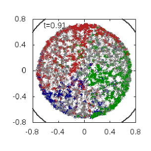
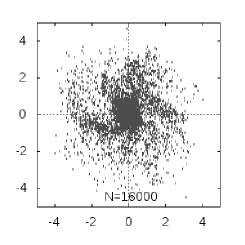
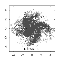
First of all, we visually examine the formation of the spiral pattern in a TC disk. Shown in Fig. 1 is the configuration of TC-B02 projected onto the disk plane at different times around the maximum contraction (see information of the presentation in caption). At the final time, we observe the trailing spiral arms emerging from three different points of the central nucleus. With a close inspection on the evolution detail, we observe at the densely-packed clumps of particles constituting the peripheral ring while the disk is collapsing. In the inner part, we observe the loosely-distributed nodes of particles attracted towards the local over-density by finite- fluctuations. There is not yet any trace of the spiral pattern at this moment but we observe a clear partition between groups of particles that eventually become each arm. At , the disk reaches the minimum size and each population contracts further, forming dense separated clouds at different locations. At , the continuous spiral arms emerge out around the dense nucleus and they are dwelling in the background with diluted density, i.e. the inter-arm region. The system size is rapidly increasing after the collapse.
We may underline from this result that although the point-wise initial condition has been drawn from an axisymmetric mass distribution function, these emerging arms are the outcome of the breaking of isotropy by the finite- effect. It triggers the separated mass concentrations and outflows before and after the collapse.

|
 |
We now inspect the procedure of violent relaxation in detail. Shown in Fig. 2 are the temporal evolutions of the fraction of ejected particles and the virial ratio calculated from all and bound particles of the same case. The ejected (or unbound) particles are those with positive energy while the bound particles correspond to those with negative energy. Considering , we observe that the ejection does not occur once but there are two events of it. The first one by gravitational collapse occurs around and it brings the fraction to . We also remark that this ejection is not punctual but it lasts for . Afterwards, this fraction remains constant until the second ejection when is boosted again during and reaches that is apparently the terminal value. This can be interpreted by that the particles at different initial positions are designated to escape at different times. In other words, the time at which each particle is ejected is -dependent. The evolution of the virial ratio of bound structure is in coherence with : it increases rapidly during the first collapse before it stays mildly sub-virialized for a period of time. Then, the secondary ejection brings it up again and relaxes down to the virialized state. On the contrary, the virial ratio of the entire structure always remains slightly above the bound one since the first ejection. This is because the ejected mass carries the excessive kinetic energy. These plots inform that, although the spiral structure in Fig. 1 appears to be fully formed at , there is still an ongoing evolution. However, we do not expect any major effect on the spiral pattern by the second wave of ejection as it occurs far inside and later in time. From these results, it turns out that the virialization of a rotating disk is delayed as it takes more than three times the collapse time because of the strong collective motion and multiple ejections.
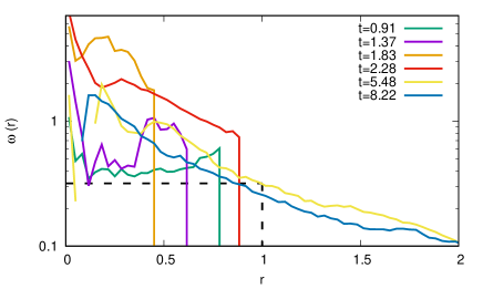
For further details on the winding process, the angular velocity as a function of radius at different times of TC-B02 is shown in Fig. 3. We find that, while the disk is shrinking from to , the particles with high angular velocities are developed near the disk boundary, forming the peripheral ring observed in Fig. 1. On the contrary, the rotational velocity of the inner part is slightly developed, allowing the separated clumps to be formed by fluctuations. In the subsequent time, the particles with high angular velocities from the boundary finally fall to the center and the disk reaches the minimum size. After the turning point, beyond develops the differential pattern because the particles reduce their angular speeds while they are travelling outwards due to the conservation of angular momentum, shearing the mass flow to become spiral arms in this process. In the innermost part, i.e. below , the rotation speed drops and becomes near zero or negative at the last two plots. This can be that this part is dominated by the more isotropic velocity distribution caused by the strongly varying potential during the violent relaxation that re-aligns the particle velocities.
To summarize the formation process of the spiral pattern in a TC disk, there are three necessary ingredients. These include the concentration of mass flow, the persisting mass ejection and the differential rotation. The formation steps can then be detailed as follows. First, while the rotating disk collectively collapses, the motions of particles are locally modulated, making the particle flows more concentrated in some paths. Then, by a combination of the continual ejection and the differential rotation due to the conservation of angular momentum, the disk center acts as the rotating source of ejection that feeds the spiral imprint of particles outwards. The formation of multi-arm pattern has also been reported for a disk in equilibrium. It has been shown that the local over-densities embedded in the disk, either by the Poissonian noise (Fujii \BOthers., \APACyear2011) or by the randomly placed giant molecular clouds (D’Onghia \BOthers., \APACyear2013), play a similar role as in our case since they can trigger the local concentrations, which are then sheared by the differential rotation and become the spiral arms.
4.2 Dependences on and
|
 |
 |
|---|
As demonstrated in Sec. 4.1, the formation of the spiral pattern in a TC disk relies on finite- fluctuations in combination with the differential rotation and ejection. We inspect further the dependence on and to the resulting arms in this disk family. First, the configurations of TC-B02 with different are shown in Fig. 4. With covering almost orders of magnitude, it becomes clear that more spiral arms are generated as we increase . For , we observe two opposite arms on the left and right of the nucleus. As goes up to , we observe four main arms with various length and thickness. These arms emerge from different random positions. Thus, they are originated from the separated flows of mass. With , the spiral arms are even more tightly arranged.
To explain and make a simple estimate for this result, we recall the procedure presented in Fig. 1. In order to establish the spiral arms, particles must be accumulated before they are driven out by the ejection. We then hypothesize that this process involves two competing collapse time-scales since the start. The first is the global time-scale, , for the entire disk which can be obtained by the dimensional approximation of the acceleration at disk boundary to be
| (11) |
where is the disk radius and is the surface density at start. In the same way, the local collapse time, , is given by
| (12) |
where ′ designates the local variables. By this definition, corresponds to the effective radius of the cloud, in which the density is equal to . We then make an assumption that the particle number forming each arm and its adjacent part is that is equally divided by the final number of arms . We then have . This proposition also implies that there are sub-collapses, hosting particles in each one, prior to the ejection. For , it is more convenient to express it as where corresponds to the deviation from in the area initially occupied by . Then, can be re-written in a linear approximation form as
| (13) |
For an arm to be successfully built, our hypothesis is that so that the concentrated cloud is set well before the maximum collapse and ejection. This can be satisfied given that
| (14) |
By some manipulation, the expression (14) yields , i.e. the local density fluctuations are of order the mean density. If the relative density is approximated by Poissonian noise as , the condition (14) otherwise gives
| (15) |
Equation (15) qualitatively agrees with the result in the way that we can have more spiral arms if more particles are introduced. However, as evaluated from Fig. 4, this expression evidently over-estimates the simulated results: the number of arms for is not eight-fold from the reference case. This might be that real process is not as simplistic as we initially thought.
|
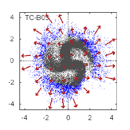 |
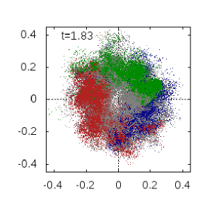
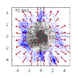
We then consider the spiral pattern with different . Shown in Fig. 5 are the configurations of two other TC at with the velocity field in an arbitrary unit. First of all, we find that the outer part of the arms is composed of the unbound particles, as expected from the primary ejection. For B03, we observe the multi-arm pattern embedded in a diluted background similar to TC-B02 and the arms are winding more around the nucleus. With , we capture instead the unwound filaments pointing outwards from the nucleus. Thus, it turns out that, in the latter case, the mass accumulation can be accomplished but it fails to wind up. The fact that the winding is enhanced if is increased from to is in line with the approximation given in equation (6). However, the failure in producing the spiral arms at low is an unexpected result as that approximation predicts rather less winding. This could be that the shearing fuelled by the initial rotation is not strong enough to withstand the violent relaxation and the local mass accumulation in the early stage, which tend to randomize the particle velocities.
For the detailed kinematics of the spiral structure, the velocity field reveals characteristic motions at different parts. We find that the nucleus and inner bound region are dominated by the tangential motion in the direction of the initial rotation. Further outwards, the motion of the outer bound region is combined between radial and tangential components. As we cross the boundary, the radial motion dominates the velocity of unbound particles, as expected from the ejection. They are travelling with far greater speed than those inside. Despite that the bound and unbound parts are dynamically dissimilar, we do not see the discontinuity between the two sides of the arms. The size of the disk and spiral arms is considerably extended from the initial size. We speculate that there are two distinct mechanisms responsible for the expansion of the disk. The first mechanism is the violent relaxation that generates an amount of ejected particles, constituting the outermost part of the system. This mechanism has been described by Joyce \BOthers. (\APACyear2009) that the late-arriving particles gain the kinetic energy from the central time-varying potential of the inside mass. Those that gain sufficiently high energies then escape from the system. We anticipate that this part will continually expand due to the non-zero terminal velocity. Another possible mechanism may be the radial migration (or radial mixing), which comes into play when the spiral pattern is formed. This mechanism describes the expansion of the disk outskirts as a consequence of the angular momentum re-distribution by the spiral disturbance (Sellwood \BBA Binney, \APACyear2002; Roskar \BOthers., \APACyear2008). Alternatively, the bar-spiral interaction (Minchev \BBA Famaey, \APACyear2010) or the passage of satellite (Quillen \BOthers., \APACyear2009; Bird \BOthers., \APACyear2013) has also been reported to cause the same migration. By this mechanism, the particles with high angular momentum gain can migrate outwards, while remaining in close orbits. This explains why the boundary of the bound structure can be further expanded although the disk is already in a virialized state.
4.3 Spiral arms from TN disks: trial for grand-design structure

|
 |
|---|---|
|
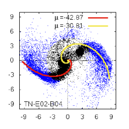 |
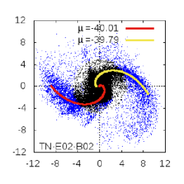
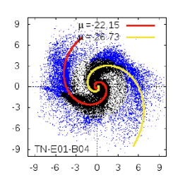
In this section, we investigate the formation of the spiral structure in TN family. To verify this, some selected TN at are illustrated in Fig. 6 with bound and unbound particles distinguished. The best-fitting spiral function (8) and the pitch angle are also put in the figures. In all cases, we observe two spiral arms emerging from the opposite sides, with unbound particles occupying more than half of their lengths. Comparing with Fig. 5, we note that the radial size of the bound mass is further expanded in the course of a few dynamical times. This is another evidence of the radial migration caused by the interaction with spiral arms.
To explain the emergence of the two controlled arms, let us recall the relating work of Benhaiem \BBA Sylos Labini (\APACyear2015). During the collapse of a non-rotating ellipsoid, they demonstrate that the inertial principal axis of ejection is strongly aligned with the initial major axis of the system. To explain this, one first recalls the analysis of the non-isotropic collapse by Lin \BOthers. (\APACyear1965). Their analysis informs that the particles at the furthest side of the ellipsoid have the longest free-fall times. As a consequence, they arrive at the center later and gain the kinetic boost from the central field created by particles arriving earlier to escape from the system. From our comprehension, that mechanism definitely plays a role in our case for guiding the ejection through the major axis. We further speculate that this alone cannot establish the visually detectable arms. We may again underline the necessity of the pre-ejection concentration as another important factor. This localized mass accumulation can also be explained by an alternated view of the same theory by Lin \BOthers. (\APACyear1965). The fact that the shortest axis has the shortest free-fall time lets it reach the origin first while the infall from the longer side is still ongoing, forcing the mass concentration to be out of the minor axis. This explains why our collapsing ellipse develops two arms, supposedly along its initial major axis. In addition, TN-E01-B01 has been tested with from . We find that the number and position of main arms can effectively be controlled in that range of . Thus, the modification of disk surface is effective to subdue the finite- effect and confine the particle concentration and ejection.
We then inspect the agreement with the best-fitting logarithmic spiral function. To determine , we first calculate the surface density of a point-wise configuration in a polar grid. Then, starting from the radius where the arm begins, the cell with maximum density residing in the visible arm is picked at each radius until the end of the arm. Finally, is obtained by fitting the positions of chosen cells with equation (8). The fitting yields negative as the arms are trailing and we will keep this sign convention for further analysis. Without the separation of nucleus, the constant- model fits well with the simulated configurations resembling to the grand-design structures. Particular concern is on TN-E02-B04 where we note the separation into two sub-nuclei, each of which attaches to its individual arm. We note slight deviations from the spiral lines of both arms due to the displacement of sub-nuclei from the origin. The separation of nucleus is possibly because high leads to a more elongated shape at collapse. Thus, it is more fragile to be torn apart by the rapid rotation.
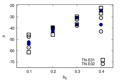
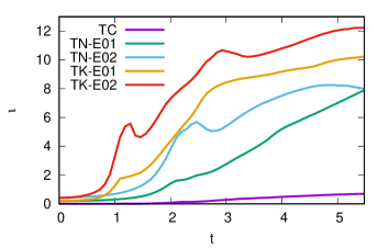
To see more quantitatively the variation of pitch angle, the plot of of all TN disks at as function of , two individual as well as the average for each case, is shown in Fig. 7. For both , we find that increases accordingly with until , i.e. the arms are more tightly wound. That tendency is retained for E01 as we progress to B04 while for E02, the winding is apparently limited from advancing higher. The dispersion of between the two arms is typically less than and apparently does not correlate with or . The fact that increases with is predicted by our estimate (6) which implies that the shearing strength increases with the initial rotation.
Let us compare the situation between TC and TN apart from the ability to control the arm position and number. The winding dynamics in both families is similar in the way that it tends to wind up more as we increase . However, this tendency is apparently limited beyond TN-E02-B03. At the lower end, the winding does not take place at TC-B01 but it does for its TN counterparts. This can be explained by that, with a guided ejection, the collective flows of mass are more intensified. Therefore, their initial motion is hardly overcome by the disturbance during the violent relaxation and is preserved until the ejection. More discussion relating to the effect from the disk configuration will be available in Sec. 4.5.
4.4 Long-time behavior of spiral arms
|
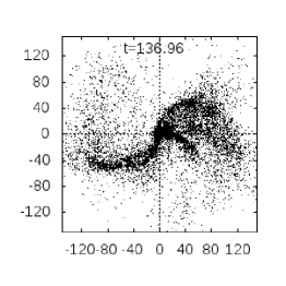 |
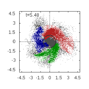
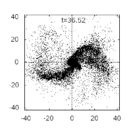
In this section, we study the long-term behavior of the spiral arms. Some TN cases are evolved further and the configuration of the prolonged TN-E01-B01 until is shown in Fig. 8. First of all, we find that the obtained spiral structure is robust: it remains in shape for time much longer than the formation time-scale without any sign of dissolution or disfigurement. Its size is much expanded from that in Fig. 6 as a result of the radially outward motion. We observe an additional morphological change of the nucleus at where another short arm emerges and stretches out rapidly as observed at . Apart from that fast emergence, there is no further change of the main arms. The overall configuration is almost self-similar by the radial stretching. The rotation is weakened so it is hardly detectable by visual inspection. This might be that the particles of the spiral arms are approaching their terminal velocities which rather follow the linear trajectories.
 |
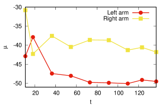 |
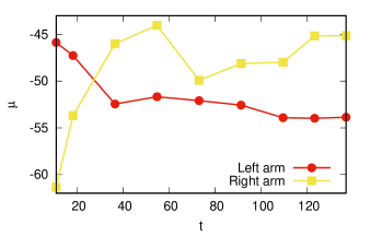
To examine the evolution of spiral arms more quantitatively, the plots of the temporal evolution of for each arm of the two most prolonged cases are depicted in Fig. 9. We observe the same behavior for three of four arms where evolves quickly (either increasing or decreasing) until . Then, it declines modestly by a few degrees over a time interval about . The evolution of the right arm of TN-E01-B01 is different as does not mark a clear increase or decrease after its sharp increase prior to . To explain the temporal evolution of , we first recall the expression of from equation (8) and re-arrange it to be
| (16) |
We then apply the time derivative to equation (16) and, after some manipulation, we obtain
| (17) |
where over the parameters indicates their time derivatives. From this expression, the sign of relies on the fraction inside the logarithm which can be seen as the ratio of the radial to tangential velocity of arm element. With , we justify that in radially and tangentially dominated evolution, the pitch angle is decreasing and increasing, respectively. Thus, the evolution of the three regular arms in Fig. 9 can be separated into two different phases. First stage is the rapid variation due to the radial and tangential velocities competing to each other, allowing the sign of to be either positive or negative. Then, when the rotational velocity mostly decays out by expansion, the motion is predominantly radial which is seen by the gentle decline of . The peculiar behavior of one irregular arm could be the result from another arm emerging rapidly beside that potentially disturbs the rectilinear and angular motions.
 |
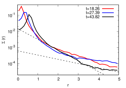 |
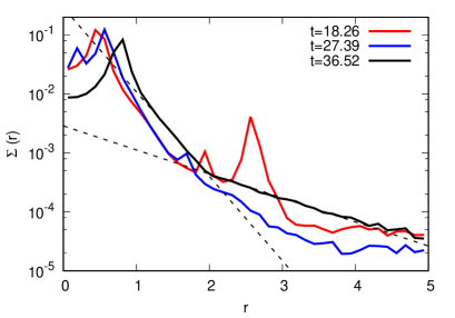
From Fig. 9, it becomes clear that the radial motion of the unbound part, which is originated from the gravitational collapse, dominates the long-term evolution of the spiral arms. We verify further the particle distribution at the inner part. Plotted in Fig. 10 is the surface density as function of radius at different times for two TN disks. For the profile at the last time, we provide the best-fitting exponential functions for two different parts of the disk. The break radii corresponds to the intersections of the two lines. We find that the surface densities of both cases are similar to the type-III (or anti-truncated) disk, which is characterized by a slower exponential drop of the density beyond the break radius. The exponential decay is retained until , which is 5 times larger than the initial size. This indicates that the radial migration is the key mechanism for expanding the boundary of the disk. The cause of the type-III density profile is conjectured to be the gas accretion into the disk outskirts, which enhances the velocity dispersion in this region (Minchev \BOthers., \APACyear2012). Although our system does not involve any accretion mechanism, we believe that the significant random motion in the disk outskirts could be the remnant of the gravitational collapse, which tends to randomize the initial rotation. This explains why the disk relaxing in this way produces the type-III profile.
4.5 Effect from increasing the thickness
|
 |
|---|---|
|
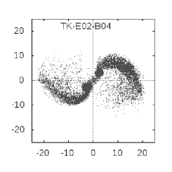 |
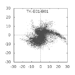
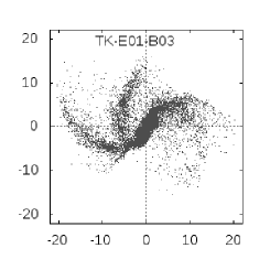
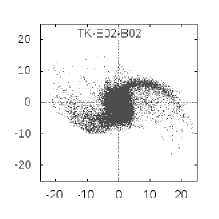
We finally consider the spiral arms in the TK family. The projections of some selected TK at are shown in Fig. 11. Similar to the TN disks, we capture the trailing spiral structures but their appearances are more diversified. We remark the imbalanced arms for TK-E01-B01 and the additional third arm on the left side for TK-E01-B03. When reaches , overall appearances do not differ much from their TN counterparts. The nucleus of TK-E02-B04 is also separated apart similar to its corresponding TN. In other words, the increase of thickness does not affect much the final forms provided that .
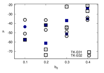
The values of of each arm and the averages for all TK cases are summarized in Fig. 12. In the plot, there are one single for TK-E01-B01 and three for each of TK-E01-B02 and TK-E01-B03. The pitch angles of the extra arms in the two latter cases are at the top-most points. For E01, the averaged for low is considerably lower than that of the corresponding TN. The third arms of both cases yield much greater than the pitch angles of normal arms. However, we still observe the increasing tendency of the averaged from B02 on, whether the third arms are incorporated or not. Particular interest is on E02. While the pitch angles are comparable to those from TN in Fig. 7 and their dispersions are relatively low, the increase of with is not evident. They are rather fluctuating around .
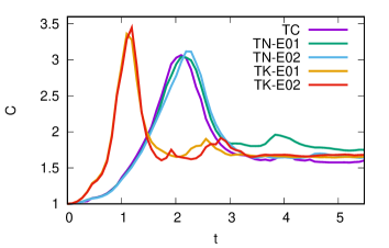
In order to understand the inconsistencies with TN disks, e.g. the diversity of the spiral structures and the non-increasing with , we will examine more parameters during the collapse and ejection. Shown in Fig. 13 are the temporal evolutions of the collapse factor and the flattening (see definitions in equations (9) and (10)) calculated from bound particles of all B03 disks. We find that all are evolving in the same way: it increases from before it relaxes down to a certain value around . The two TK disks evidently yield the maximum greater than those attained by the three thin cases. It appears that, with more disk thickness, the infall from third axis makes the contraction more compact. For the evolution of , it remains low until the end for TC. Thus, we may infer that the non-circular effect is negligible here. The situation is different for TN and TK where rises in accordance with until it reaches the maximum. Afterwards, it is still increasing at a slower rate. The values of at the maximum contraction of TN and TK are almost equal but, further from that time, the TK disks develop higher flattening than that of TN until the end of plot.
 |
 |
These results suggest that the TK disks become more compact and more elongated at the collapse than their TN counterparts. We speculate that these are the causes of the inconsistencies with TN disks as we will explain as follows. Around the maximum contraction, the highly non-axisymmetric field can potentially alter the motion of particles which are arranged by the collective rotation beforehand. Therefore, the effect of the initial rotation is washed away as seen in Fig. 12 where struggles or fails to increase with . The additional effect from a highly asymmetric field is also seen in TN-E02 and TK since we observe that the particles gather closer to the arms than in TN-E01 and TC, in which they diffuse throughout the inter-arm region (see Fig. 6). This is another indication of the forcefully guided ejection by the self-consistent potential in TN-E02 and TK. To resolve the cause of the diversity of spiral patterns, we suspect that it is the deeper potential field at collapse, indicated by the maximum , that splits the concentrations apart before the ejection, leading to the separated arms on the same side of nucleus. However, this occurrence is not observed for TK-E02 because stronger asymmetric field created by higher can confine the mass more effectively on each side thus it is more resistant to the central potential.
5 Conclusion and discussion
In this work, we explore the spontaneous formation of the spiral structure by gravitational collapse of a rigidly rotating disk. From the start, the disk collapses and expands differentially so that the mass outflow with density amplified is sheared and forms finally the spiral pattern when looking on the disk plane. Although trailing spiral arms are generic for all disk families, a careful consideration suggests that their properties are different. In TC disks, the absence of surface asymmetry leads to the formation of multi-arm pattern regulated by the Poissonian noise. In the formation process, the particles forming each arm are separately grouping by local over-densities before they are ejected out. This mechanism, in turn, leads to the spiral structure with the number of arms that increases with the particle number. For TN family, a slight modification on disk surface can confine the clustering along the longer axis of the elliptical disk and guide the ejection through the same axis. This yields the final structure with two prominent spiral arms on the opposite sides of nucleus similar to the grand-design configuration. In these two families, the pitch angles of the spiral arms tend to vary in accordance with the degree of initial rotation. When we increase the thickness, corresponding to the TK group, the situation is more difficult as the relaxation leads to more visually complicated structures or it even dissociates the winding degree from the initial rotation in some condition. We suspect that these discrepancies are caused by a deep non-axisymmetric central potential at collapse that splits apart the mass concentration and intervenes the pattern of the pre-collapse motion.
About the kinematics of simulated arms, they are non-stationary as the outer unbound part is continually moving outwards. The inner bound part that consists of the virialized nucleus and the beginning of arms is, on the contrary, dominated by the tangential motion. The surface density of the disk at the vicinity of nucleus also matches with the type-III profile. This is an evidence of the radial migration that arranges the disk outskirts. Despite the continual expansion, these arms are robust as they remains intact for a long period of time. The expansion affects only by decreasing slowly the pitch angle. These characteristic motion and longevity are different from those of the arms in real galaxies that are dominated by the differential rotation and it is believed that they will dissolve after a number of rotations. Although the properties of our spiral arms are incompatible with the observed arms, the fact that this kind of spiral structure (and also those in Benhaiem \BOthers. (\APACyear2017)) is obtainable through the violent gravitational collapse lets us speculate that this type of spiral structure could arise in the realm where the galaxy relaxes straight from a monolithic collapse. For an unstable protogalatic cloud that possesses some amount of rotation, our mechanism suggests that the spiral structure can potentially emerge out. The analysis of a cloud collapse in the cosmological framework suggests that the relaxation of an overdense cloud should be terminated and becomes galaxy around (Partridge \BBA Peebles, \APACyear1967). Thus, if the proposed spiral structure exists, they might reside in that range of redshift. To pinpoint them, the characteristic velocity field is a useful identification tool.
Acknowledgements
This project is supported by \fundingAgencyThe Institute for the Promotion of Teaching Science and Technology (IPST) via the Research Fund for DPST Graduate with First Placement (in fiscal year 2559 BE with contract number \fundingNumber003/2559) under the mentorship of Khamphee Karwan. Numerical simulations are facilitated by HPC resources of Chalawan cluster of the National Astronomical Research Institute of Thailand (NARIT).
References
- Aguilar \BBA Merritt (\APACyear1990) \APACinsertmetastaraguilar+merritt_1990{APACrefauthors}Aguilar, L\BPBIA.\BCBT \BBA Merritt, D. \APACrefYearMonthDay1990, \APACjournalVolNumPagesAstrophys. J.35433. \PrintBackRefs\CurrentBib
- Barnes \BOthers. (\APACyear2009) \APACinsertmetastarbarnes+lanzel+williams_2009{APACrefauthors}Barnes, E\BPBII., Lanzel, P\BPBIA.\BCBL \BBA Williams, L\BPBIL\BPBIR. \APACrefYearMonthDay2009, \APACjournalVolNumPagesAstrophys. J.704372. \PrintBackRefs\CurrentBib
- Benhaiem \BOthers. (\APACyear2017) \APACinsertmetastarbenhaiem_et_al_2017{APACrefauthors}Benhaiem, D., Joyce, M.\BCBL \BBA Sylos Labini, F. \APACrefYearMonthDay2017, \APACjournalVolNumPagesAstrophys. J.85119. \PrintBackRefs\CurrentBib
- Benhaiem \BBA Sylos Labini (\APACyear2015) \APACinsertmetastarbenhaiem+sylos_labini_2015{APACrefauthors}Benhaiem, D.\BCBT \BBA Sylos Labini, F. \APACrefYearMonthDay2015\APACmonth04, \APACjournalVolNumPagesMon. Not. R. Astron. Soc.4482634-2643. \PrintBackRefs\CurrentBib
- Benhaiem \BOthers. (\APACyear2019) \APACinsertmetastarbenhaiem_et_al_2019{APACrefauthors}Benhaiem, D., Sylos Labini, F.\BCBL \BBA Joyce, M. \APACrefYearMonthDay2019, \APACjournalVolNumPagesPhys. Rev. E99022125. \PrintBackRefs\CurrentBib
- Bird \BOthers. (\APACyear2013) \APACinsertmetastarbird_et_al_2013{APACrefauthors}Bird, J\BPBIC., Kazantzidis, S., Weinberg, D\BPBIH., Guedes, J., Callegari, S., Mayer, L.\BCBL \BBA Madau, P. \APACrefYearMonthDay2013, \APACjournalVolNumPagesAstrophys. J.77343. \PrintBackRefs\CurrentBib
- Boily \BBA Athanassoula (\APACyear2006) \APACinsertmetastarboily+athanassoula_2006{APACrefauthors}Boily, C\BPBIM.\BCBT \BBA Athanassoula, E. \APACrefYearMonthDay2006, \APACjournalVolNumPagesMon. Not. R. Astr. Soc.369608. \PrintBackRefs\CurrentBib
- Ciftja \BBA Hysi (\APACyear2011) \APACinsertmetastarciftja+hysi_2011{APACrefauthors}Ciftja, O.\BCBT \BBA Hysi, I. \APACrefYearMonthDay2011, \APACjournalVolNumPagesAppl. Math. Lett.241919. \PrintBackRefs\CurrentBib
- D’Onghia \BOthers. (\APACyear2013) \APACinsertmetastardonghia_et_al_2013{APACrefauthors}D’Onghia, E., Vogelsberger, M.\BCBL \BBA Hernquist, L. \APACrefYearMonthDay2013, \APACjournalVolNumPagesAstrophys. J.76634. \PrintBackRefs\CurrentBib
- Fujii \BOthers. (\APACyear2011) \APACinsertmetastarfujii_et_al_2011{APACrefauthors}Fujii, M\BPBIS., Baba, J., Saitoh, T\BPBIR., Makino, J., Kokubo, E.\BCBL \BBA Wada, K. \APACrefYearMonthDay2011, \APACjournalVolNumPagesAstrophys. J.730109. \PrintBackRefs\CurrentBib
- Goldreich \BBA Lynden-Bell (\APACyear1965) \APACinsertmetastargoldreich+lynden_bell_1965b{APACrefauthors}Goldreich, P.\BCBT \BBA Lynden-Bell, D. \APACrefYearMonthDay1965, \APACjournalVolNumPagesMon. Not. R. Astron. Soc.130125. \PrintBackRefs\CurrentBib
- Gott (\APACyear1973) \APACinsertmetastargott_1973{APACrefauthors}Gott, J\BPBIR. \APACrefYearMonthDay1973, \APACjournalVolNumPagesAstrophys. J.186481. \PrintBackRefs\CurrentBib
- Joyce \BOthers. (\APACyear2009) \APACinsertmetastarjoyce+marcos+sylos_labini_2009{APACrefauthors}Joyce, M., Marcos, B.\BCBL \BBA Sylos Labini, F. \APACrefYearMonthDay2009, \APACjournalVolNumPagesMon. Not. R. Astr. Soc.397775. \PrintBackRefs\CurrentBib
- Katz (\APACyear1991) \APACinsertmetastarkatz_1991{APACrefauthors}Katz, N. \APACrefYearMonthDay1991, \APACjournalVolNumPagesAstrophys. J.368325. \PrintBackRefs\CurrentBib
- Levin \BOthers. (\APACyear2008) \APACinsertmetastarlevin+pakter+rizzato_2008{APACrefauthors}Levin, Y., Pakter, R.\BCBL \BBA Rizzato, F\BPBIB. \APACrefYearMonthDay2008, \APACjournalVolNumPagesPhys. Rev. E78021130. \PrintBackRefs\CurrentBib
- Lin \BOthers. (\APACyear1965) \APACinsertmetastarlin+mestel+shu_1965{APACrefauthors}Lin, C\BPBIC., Mestel, L.\BCBL \BBA Shu, F\BPBIH. \APACrefYearMonthDay1965, \APACjournalVolNumPagesAstrophys. J.1421431. \PrintBackRefs\CurrentBib
- Lin \BBA Shu (\APACyear1964) \APACinsertmetastarlin+shu_1964{APACrefauthors}Lin, C\BPBIC.\BCBT \BBA Shu, F\BPBIH. \APACrefYearMonthDay1964, \APACjournalVolNumPagesAstrophys. J.140646. \PrintBackRefs\CurrentBib
- Lynden-Bell (\APACyear1967) \APACinsertmetastarlynden_bell_1967{APACrefauthors}Lynden-Bell, D. \APACrefYearMonthDay1967, \APACjournalVolNumPagesMon. Not. R. Astr. Soc.136101. \PrintBackRefs\CurrentBib
- Minchev \BBA Famaey (\APACyear2010) \APACinsertmetastarminchev+famaey_2010{APACrefauthors}Minchev, I.\BCBT \BBA Famaey, B. \APACrefYearMonthDay2010, \APACjournalVolNumPagesAstrophys. J.722112. \PrintBackRefs\CurrentBib
- Minchev \BOthers. (\APACyear2012) \APACinsertmetastarminchev_et_al_2012{APACrefauthors}Minchev, I., Famaey, B., Quillen, A\BPBIC. et al. \APACrefYearMonthDay2012, \APACjournalVolNumPagesAstron. Astrophys.548126. \PrintBackRefs\CurrentBib
- Partridge \BBA Peebles (\APACyear1967) \APACinsertmetastarpartridge+peebles_1967a{APACrefauthors}Partridge, R\BPBIB.\BCBT \BBA Peebles, P\BPBIJ\BPBIE. \APACrefYearMonthDay1967, \APACjournalVolNumPagesAstrophys. J.147868. \PrintBackRefs\CurrentBib
- Quillen \BOthers. (\APACyear2009) \APACinsertmetastarquillen_et_al_2009{APACrefauthors}Quillen, A\BPBIC., Minchev, I., Bland-Hawthorn, J.\BCBL \BBA Haywood, M. \APACrefYearMonthDay2009, \APACjournalVolNumPagesMon. Not. R. Astr. Soc.3971599. \PrintBackRefs\CurrentBib
- Roskar \BOthers. (\APACyear2008) \APACinsertmetastarroskar_et_al_2008{APACrefauthors}Roskar, R., Debattista, V\BPBIP., Quinn, T\BPBIR., Stinson, G\BPBIS.\BCBL \BBA Wadsley, J. \APACrefYearMonthDay2008, \APACjournalVolNumPagesAstrophys. J. Lett.68479. \PrintBackRefs\CurrentBib
- Roy \BBA Perez (\APACyear2004) \APACinsertmetastarroy+perez_2004{APACrefauthors}Roy, F.\BCBT \BBA Perez, J. \APACrefYearMonthDay2004, \APACjournalVolNumPagesMon. Not. R. Astr. Soc.34862. \PrintBackRefs\CurrentBib
- Sellwood \BBA Binney (\APACyear2002) \APACinsertmetastarsellwood+binney+2002{APACrefauthors}Sellwood, J\BPBIA.\BCBT \BBA Binney, J\BPBIJ. \APACrefYearMonthDay2002, \APACjournalVolNumPagesMon. Not. R. Astr. Soc.336785. \PrintBackRefs\CurrentBib
- Springel (\APACyear2005) \APACinsertmetastarspringel_2005{APACrefauthors}Springel, V. \APACrefYearMonthDay2005, \APACjournalVolNumPagesMon. Not. R. Astr. Soc.3641105. \PrintBackRefs\CurrentBib
- Springel \BOthers. (\APACyear2001) \APACinsertmetastarspringel+yoshida+white_2001{APACrefauthors}Springel, V., Yoshida, N.\BCBL \BBA White, S\BPBID\BPBIM. \APACrefYearMonthDay2001, \APACjournalVolNumPagesNew Astron.679. \PrintBackRefs\CurrentBib
- Sylos Labini (\APACyear2013) \APACinsertmetastarsylos_labini_2013{APACrefauthors}Sylos Labini, F. \APACrefYearMonthDay2013, \APACjournalVolNumPagesMon. Not. R. Astr. Soc.429679. \PrintBackRefs\CurrentBib
- Toomre \BBA Toomre (\APACyear1972) \APACinsertmetastartoomre+toomre_1972{APACrefauthors}Toomre, A.\BCBT \BBA Toomre, J. \APACrefYearMonthDay1972\APACmonth12, \APACjournalVolNumPagesAstrophys. J.178623-666. \PrintBackRefs\CurrentBib
- Trenti \BOthers. (\APACyear2005) \APACinsertmetastartrenti_et_al_2005{APACrefauthors}Trenti, M., Bertin, G.\BCBL \BBA van Albada, T\BPBIS. \APACrefYearMonthDay2005, \APACjournalVolNumPagesAstron. Astrophys.43357. \PrintBackRefs\CurrentBib