Pinched Hysteresis Loops In Nonlinear Resonators††thanks: The paper has been accepted at IET Circuits, Devices and Systems
Abstract
This paper shows that pinched hysteresis can be observed in simple nonlinear resonance circuits containing a single diode that behaves as a voltage-controlled switch. Mathematical models are derived and numerically validated for both series and parallel resonator circuits. The lobe area of the pinched loop is found to increase with increased frequency and multiple pinch-points are possible with an odd symmetrical nonlinearity such as a cubic nonlinearity. Experiments have been performed to prove the existence of pinched hysteresis with a single diode and with two anti-parallel diodes. The formation of a pinched loop in these circuits confirms that: 1) pinched hystersis is not a finger-print of memristors and that 2) the existence of a nonlinearity is essential for generating this behavior. Finally, an application in a digital logic circuit is validated.
Keywords Nonlinear circuits Resonator memristor Pinched Hysteresis
1 Introduction
Memristors have been proposed as new electronic devices with promising analog/digital and neuromorphic applications [1, 2, 3, 4, 5, 6]. Their characteristic behavior is a pinched hysteresis loop in the current-voltage plane [7]. Many circuits (known as emulators) have been introduced to mimic the memristor’s behavior [8, 9, 10, 11, 12]. Although this behavior has been shown to exist in other nonlinear devices such as a non-linear inductor or a non-linear capacitor [13, 14, 15], and that its appearance is linked to satisfying the necessary conditions of the theory of Lissajous figures [16, 17, 18], it is still mistakenly attributed to memristors only. There are actually doubts about the uniqueness of the memristor as a fundamental device which have been raised by several researchers (see [19] and the references therein) but there is no doubt that it is a dynamic and nonlinear device [20, 10, 21]. Without being nonlinear, the frequency-doubling mechanism mandated by the theory of Lissajous figures, which is essential to create a pinched loop (as explained in detail in [16] and most recently in [22]) cannot be obtained. It is important to note that even if the memristor was not a fundamental device, it may still be a useful nonlinear device. Therefore, semi-conductor devices labeled as memristors continue to be fabricated in different technologies and materials [23, 24] and are now commercially available from some vendors (see for example www.knowm.com).
where and are the input and output of the system and is the state variable. To identify a device as a memristor, it has to have three fingerprints [27, 26] : 1) a pinched loop in current-voltage plane with 2) a loop area that decreases monotonically with increasing frequency and 3) shrink to a single-valued function when the frequency tends to infinity. This does not mean that pinched hysteresis loops cannot be observed in other devices or circuits (with increasing or decreasing loop area).
In this paper, we provide two examples of simple fundamental circuits, namely nonlinear series and parallel resonators, that can exhibit the pinched hysteresis loop behavior. Mathematical models are derived and numerically validated with a diode-type asymmetric switching nonlinearity and also with an odd-symmetric nonlinearity formed of two anti-parallel diodes. Experimental results are provided and confirm the theory. The formation of a pinched loop from these circuits confirms our previous assertions [13, 16] that:
-
1.
pinched hystersis is not a finger-print of memristors only,
-
2.
pinched loops with lobe area widening (rather than declining) with increased frequency are possible and
-
3.
the existence of a nonlinearity is essential for generating this behavior. This is because the theory of Lissajous figures necessitates the generation of a second harmonic frequency in the electrical current when the applied voltage on the device has only one fundamental frequency (see [22] for a more detailed explanation).
2 Nonlinear resonators
2.1 Series RLC Resonator
A simple nonlinear resonator circuit is shown in Fig. 1 composed of a series RLC resonance circuit interrupted by a voltage-controlled switching nonlinearity (denoted ) placed across the capacitor. The circuit is excited by a sinusoidal signal . In its simplest form, the switching device can be a single diode and in this case the circuit is described by the equation set
| (1a) | |||
| (1b) | |||
where and are respectively the voltage and current across the capacitor and in the inductor while is the nonlinear device current given by
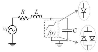
| (2) |
where is the diode switch-on resistance while is the switch-on voltage (approximately for silicon devices). Introducing the dimensionless variables: , a normalized frequency and a normalized time , the above equations transform into
| (3a) | |||
| (3b) | |||
with being the sinusoidal excitation and being the nonlinearity. In the case of the switching-diode, is asymmetric and given by
| (4) |
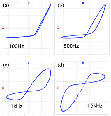
Numerical simulations of this model were performed using the ode45 solver in MATLAB with for different values of and as shown in Figs. 2(a) and 2(b) which plot the observed pinched loop in the plane; i.e. in the plane of the circuit. Therefore, this pinched-loop represents an impedance analogous to the "memristance". It is noted from these simulations that the lobe area increases with increasing the value of the parameter and also with increasing the frequency . Note that can also be written as where is the resonance frequency and is the resonance bandwidth. Hence, satisfying a certain value of is achieved not only by changing the applied excitation signal frequency but also by adjusting the resonance bandwidth and resonance frequency.
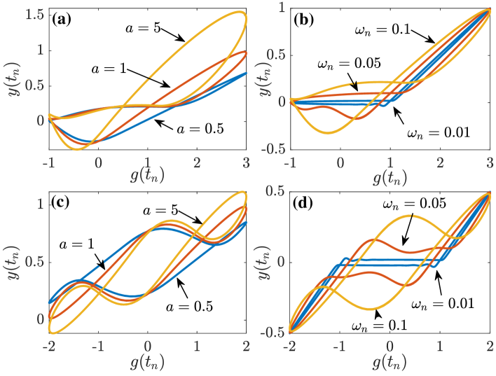
Based on the detailed analysis and explanation of [16], the appearance of the pinched loop in this nonlinear resonator is a result of satisfying the conditions of the theory of Lissajous figures. In particular, the nonlinearity is responsible for generating a strong second-harmonic in the current signal with a normalized frequency . The existence of this harmonic can easily be verified from the FFT of . So long as the phase shift between this harmonic and the fundamental frequency component remains less than , the pinched-loop will be observable [16]. The location of the pinch point can be found using the general equations derived in [16]. When the diode-type nonlinearity is replaced with an odd-symmetric one, such as a cubic-type nonlinearity or the nonlinearity resulting from two anti-parallel diodes given by (5) (see appendix), two pinched-points are obtained in this case as shown in Figs. 2(c) and (d) for the parameter values and .A pure sinusoid is used in this case for excitation ().
| (5) |
Shaping of the pinched-loop is thus clearly related to the choice of the function . In particular, the odd-symmetric nonlinearity generates a third-order harmonic from the applied fundamental frequency of the excitation voltage. The total number of pinch points in a Lissajous figure formed from two sinusoids with frequencies and is known to equal which is equal to 2 when and .
2.2 Parallel RLC Resonator
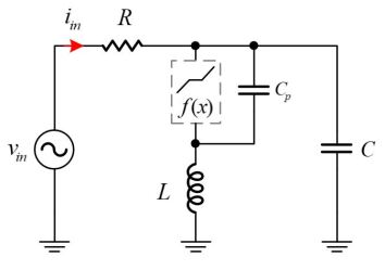
Another nonlinear resonator circuit is shown in Fig. 3 composed of a parallel RLC resonance circuit interrupted by nonlinearity placed in series with the inductor. is a parasitic capacitor that must be included in the analysis since the non-linearity is voltage-controlled. In this case the circuit is described by the equation set
| (6a) | |||
| (6b) | |||
| (6c) | |||
With the same dimensionless variables introduced in the previous subsection, the above equations can be written as
| (7a) | |||
| (7b) | |||
| (7c) | |||
where , and is the switching nonlinearity function given by (4) or (5). When tends to zero, (7c) yields .
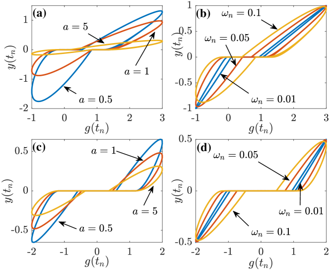
Figure 4 shows the numerical simulation of (7) with and . The area enclosed inside the lobes increases with increasing the frequency but decreases with increasing the value of parameter .
3 Experimental results
The nonlinear series resonator circuit was experimentally tested with discrete components , , and using a 1N914 diode. Figure 5 shows the observed pinched loop when the excitation voltage has an offset voltage , an amplitude of and at different frequencies. The current in the resistor was measured using a differential probe.
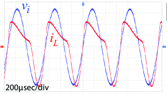
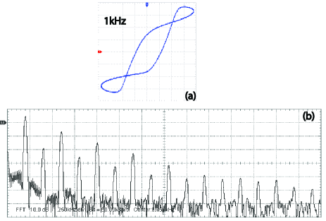
At (see Fig. 5(a)) it is seen that the portrait resembles the diode characteristics as expected. As frequency increases, the pinched loop formation is observed in Figs. 5(b), (c) and (d). The voltage and current waveforms corresponding to the portrait of Fig. 5(d) are shown in Fig. 6. Adding another diode with opposite polarity in parallel to the diode in the circuit, a loop with two pinch points is seen in Fig. 7(a) as predicted numerically. The applied voltage in this case had no offset value (), an amplitude of and a frequency. The corresponding power spectrum of the current signal is shown in Fig. 7(b) from which it is visible that strong odd harmonics have been generated. However, the two pinched points are created because the phase angle between the fundamental signal at and the generated third-order harmonic at is less than satisfying the Lissajous conditions [16]. The remaining harmonics contribute to the shape of the loop but not to the creation of the pinch-points.
4 Application and Comparison with a Commercial Memristor Device
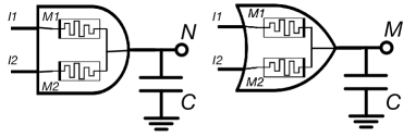
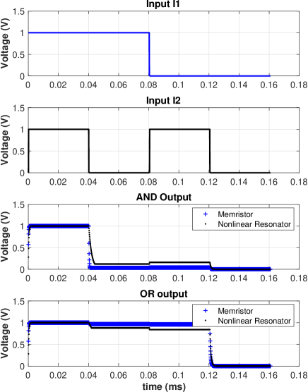
Digital application of AND/OR gates are used to compare their functionality with pinched loops created (i) from the series resonator described above and (ii) from a KNOWM commercial memristor device using their discovery kit [30]. The gates are built using two memristor devices, as shown in Fig. 8, driving a capacitive load (C = 10nF). Figure 9 shows the waveform on the capacitor for both the AND/OR gates after using the experimental memristance data of the pinched loop obtained from the nonlinear resonator circuit and that obtained from a commercial memristor device [30]. It is clear from the figure that similar responses are obtained in both cases. Therefore, from an application point of view, what matters is the existence of the pinched loop rather than its origin. On the other hand, resonators are easily realizable on the micro and nano scales [31, 32] which paves the way for possibly easier implementations of memristors based on the technique presented here. In terms of the non-volatility of these circuits, a procedure to dis-connect the ground terminal connection should be devised in order to maintain the states of the state variables (inductor current and capacitor voltage) un-changed. It is important to mention, that the non-volatility of memristors is not related to whether they are fundamental devices or not.
5 Conclusion
We have verified numerically and experimentally the existence of a dynamic pinched-loop behavior in a simple nonlinear resonator circuits. The key behind generating such a loop is to produce in the electrical current a second-order harmonic (for a single pinch point case) or third-order harmonic (for a two pinch point case) from the applied fundamental frequency of the excitation voltage. When these harmonics have proper phase and amplitude relations with respect to the fundamental [16], pinched loops appear. The circuits presented here rely on the diode nonlinearity as opposed to MOS transistor quadratic nonlinearity [17, 23] or multiplier-type nonlinearity [10, 33]. The proposed systems represent second-order and third-order dynamical systems which is not the case of memrisitve systems as defined in [25].
Appendix: Anti-parallel connected diodes
The total current of the anti-parallel-connected diodes is
| (8) |
Assuming that and are forward and backward connected, respectively, then
| (11) | |||
| (14) |
thus,
| (15) |
which results in eqn. (5) .
References
- [1] Sangho Shin, Kyungmin Kim, and Sung-Mo Kang. Memristor applications for programmable analog ICs. IEEE Trans. Nanotechnology, 10(2):266–274, 2010.
- [2] Mohammed Affan Zidan, Hesham Omran, Ahmed Sultan, Hossam AH Fahmy, and Khaled N Salama. Compensated readout for high-density mos-gated memristor crossbar array. IEEE Trans. Nanotechnology, 14(1):3–6, 2014.
- [3] ME Fouda, F Kurdahi, A Eltawil, and E Neftci. Spiking neural networks for inference and learning: A memristor-based design perspective. arXiv preprint arXiv:1909.01771, 2019.
- [4] Kechuan Wu and Xiaoping Wang. Enhanced memristor-based mnns performance on noisy dataset resulting from memristive stochasticity. IET Circuits, Devices & Systems, 13(5):704–709, 2019.
- [5] Ahmad Karimi and Abdalhossein Rezai. Novel design for memristor-based n to 1 multiplexer using new imply logic approach. IET Circuits, Devices & Systems, 13(5):647–655, 2019.
- [6] Mohamed E Fouda and Ahmed G Radwan. Memristor-based voltage-controlled relaxation oscillators. International Journal of Circuit Theory and Applications, 42(10):1092–1102, 2014.
- [7] Alon Ascoli, Stefan Slesazeck, Hannes Mähne, Ronald Tetzlaff, and Thomas Mikolajick. Nonlinear dynamics of a locally-active memristor. IEEE Trans. Circuits and Systems I: Regular Papers, 62(4):1165–1174, 2015.
- [8] Rajeev Kumar Ranjan, Surendra Sagar, Subrato Roushan, Bharti Kumari, Nishtha Rani, and Fabian Khateb. High-frequency floating memristor emulator and its experimental results. IET Circuits, Devices & Systems, 13(3):292–302, 2018.
- [9] Predrag B Petrović. Tunable flux-controlled floating memristor emulator circuits. IET Circuits, Devices & Systems, 13(4):479–486, 2019.
- [10] Ahmed S Elwakil, Mohamed E Fouda, and Ahmed Gomaa Radwan. A simple model of double-loop hysteresis behavior in memristive elements. IEEE Trans. Circuits and Systems II: Express Briefs, 60(8):487–491, 2013.
- [11] Abdullah G Alharbi, Mohammed E Fouda, Zainulabideen J Khalifa, and Masud H Chowdhury. Electrical nonlinearity emulation technique for current-controlled memristive devices. IEEE Access, 5:5399–5409, 2017.
- [12] Mohamed E Fouda and Ahmed G Radwan. Simple floating voltage-controlled memductor emulator for analog applications. Radioengineering, 23(3):944–948, 2014.
- [13] Mohamed E Fouda, Ahmed S Elwakil, and Ahmed Gomaa Radwan. Pinched hysteresis with inverse-memristor frequency characteristics in some nonlinear circuit elements. Microelectronics Journal, 46(9):834–838, 2015.
- [14] Fernando Corinto and Alon Ascoli. Memristive diode bridge with lcr filter. Electronics letters, 48(14):824–825, 2012.
- [15] J Sadecki and W Marszalek. Analysis of a memristive diode bridge rectifier. Electronics Letters, 55(3):120–122, 2019.
- [16] Brent Maundy, Ahmed S Elwakil, and Costas Psychalinos. Correlation between the theory of lissajous figures and the generation of pinched hysteresis loops in nonlinear circuits. IEEE Trans. Circuits and Systems I: Regular Papers, 66(7):2606–2614, 2019.
- [17] Brent Maundy, Ahmed Elwakil, and Costas Psychalinos. Simple MOS-based circuit designed to show pinched hysteresis behavior. Int. J. Circuit Theory and Applications, 46(5):1123–1128, 2018.
- [18] Veith A Weilnhammer, Philipp Sterzer, and Guido Hesselmann. Perceptual stability of the Lissajous figure is modulated by the speed of illusory rotation. PloS one, 11(8):e0160772, 2016.
- [19] Isaac Abraham. The case for rejecting the memristor as a fundamental circuit element. Scientific reports, 8(1):10972, 2018.
- [20] R Riaza. Comment: Is memristor a dynamic element? Electronics Letters, 50(19):1342–1344, 2014.
- [21] W. Hu and R. Wei. An analytic approach to nonlinearity analysis of memristor. IEEE Trans. Electron Devices, 66(6):2589–2594, June 2019.
- [22] S. Majzoub, A.S. Elwakil, C. Psychalinos, and B.J. Maundy. On the mechanism of creating pinched hysteresis loops using a commercial memristor device. AEU - Int. J. Electronics and Communications, 111:152923, 2019.
- [23] Yunus Babacan, Abdullah Yesil, and Fatih Gul. The fabrication and MOSFET-only circuit implementation of semiconductor memristor. IEEE Trans. on Electron Devices, 65(4):1625–1632, 2018.
- [24] L. Ge, W. Xuan, S. Liu, S. Huang, X. Wang, S. Dong, H. Jin, and J. Luo. Biomaterial Gelatin film based crossbar structure resistive switching devices. IEEE Transactions on Nanotechnology, 17(1):78–83, Jan 2018.
- [25] Leon O Chua and Sung Mo Kang. Memristive devices and systems. Proceedings of the IEEE, 64(2):209–223, 1976.
- [26] Ahmed G Radwan and Mohammed E Fouda. On the mathematical modeling of memristor, memcapacitor, and meminductor, volume 26. Springer, 2015.
- [27] Shyam Prasad Adhikari, Maheshwar Pd Sah, Hyongsuk Kim, and Leon O Chua. Three fingerprints of memristor. IEEE Transactions on Circuits and Systems I: Regular Papers, 60(11):3008–3021, 2013.
- [28] B. Chen, H. Yang, F. Zhuge, Y. Li, T. Chang, Y. He, W. Yang, N. Xu, and X. Miao. Optimal tuning of memristor conductance variation in spiking neural networks for online unsupervised learning. IEEE Trans. Electron Devices, 66(6):2844–2849, June 2019.
- [29] Y. Zhao, C. Fang, X. Zhang, X. Xu, T. Gong, Q. Luo, C. Chen, Q. Liu, H. Lv, Q. Li, F. Zhang, L. Li, and M. Liu. A compact model for drift and diffusion memristor applied in neuron circuits design. IEEE Trans. Electron Devices, 65(10):4290–4296, Oct 2018.
- [30] https://knowm.com/collections/frontpage/products/memristor-discovery-v2-kit.
- [31] N. Jaber, M. A. Hafiz, S. N. Kazmi, M. H. Hasan, F. Alsaleem, S. Ilyas, and M. I. Younis. Efficient excitation of micro/nano resonators and their higher order modes. Scientific reports, 9(319), Jan. 2019.
- [32] A.Z. Hajjaj, N. Jaber, S. Ilyas, F.K. Alfosail, and M.I. Younis. Linear and nonlinear dynamics of micro and nano-resonators: Review of recent advances. Int. J. Non-Linear Mechanics, 119:103328, 2020.
- [33] J. Jin and L. Cui. Fully integrated memristor and its application on the scroll-controllable hyperchaotic system. Complexity, (4106398):doi.org/10.1155/2019/4106398, 2019.