The impact of applying WildCards to disabled modules for FTK pattern banks on efficiency and data flow
Abstract
Online selection is an essential step to collect the most relevant collisions from the very large number of collisions inside the ATLAS detector at the Large Hadron Collider (LHC). The Fast TracKer (FTK) is a hardware based track finder, built to greatly improve the ATLAS trigger system capabilities for identifying interesting physics processes through track-based signatures. The FTK is reconstructing after each Level-1 trigger all tracks with GeV, such that the high-level trigger system gains access to track information at an early stage. FTK track reconstruction starts with a pattern recognition step. Patterns are found with hits in seven out of eight possible detector layers.
Disabled detector modules, as often encountered during LHC operation, lead to efficiency losses. To recover efficiency, WildCard (WC) algorithms are implemented in the FTK system. The WC algorithm recovers inefficiency but also causes high combinatorial background and thus increased data volumes in the FTK system, possibly exceeding hardware limitations. To overcome this, a refined algorithm to select patterns is developed and investigated in this article.
1 Introduction
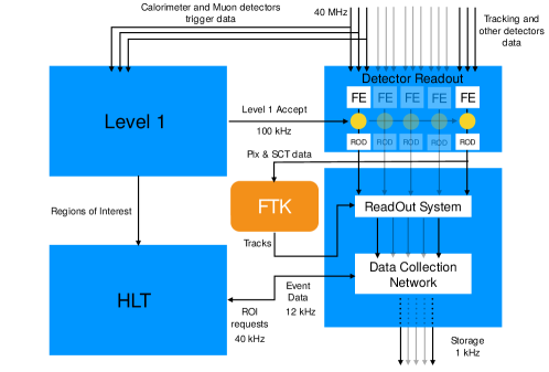
The ATLAS trigger system HLT2016 is a combination of a hardware-based Level 1 and software-based High Level Trigger (HLT), which reduces the event rate from 40 MHz to an average output rate of 1 kHz. The Fast TracKer (FTK) Annovi2013 is a track finding system for use with the ATLAS trigger, that finds and reconstructs tracks for each event that passes the Level 1 trigger. Tracks are reconstructed with an average latency of at an event input rate of kHz. The FTK system uses data from the pixel detector and the semiconductor tracker (SCT) and is designed to operate at instantaneous luminosities up to cm-2 s-1. After processing, FTK provides the helix parameters and hits for all tracks with GeV to the HLT. The dataflow in the ATLAS trigger system including the FTK is shown in Figure 1.
Handling the required amount of data is a serious design challenge. To deal with the large input data volume and rate, FTK uses a highly parallelised system, divided into 64 independent regions. The division is made in 16 azimuthal segments, each of which is further divided into 4 segments in polar angle. As of mid 2018, a partial FTK system is operational, covering a few selected regions. Hardware installation and commissioning of the full system is ongoing.
During operation with the LHC, tracking detectors may encounter problems, which can lead to disabled detector modules. These do not provide useful hit information and cause inefficiencies in the FTK track reconstruction. To recover efficiency, a WildCard (WC) algorithm is implemented in the FTK. Disabled modules on which WCs are set, are treated as if all their channels were on for each event. This does recover efficiency losses, but leads to a sizable increase in the number of fake track segments, which has the potential to slow down or even saturate the FTK system. To control these effects, modifications to the pattern selection scheme are implemented that reduce the amount of data while keeping a reasonable track reconstruction efficiency.
The FTK system design is described in section 2. The pattern selection is presented in section 3. The effect of disabled modules and details of the algorithm to control the number of fake track segments are described in section 4. The results are discussed in section 5.
2 FTK system design
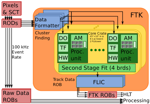
The FTK system is schematically shown in Figure 2. Briefly, the individual components take the following roles:
-
•
The pixel and strip data are transmitted from the Read Out Drivers (ROD) to the Data Formatters (DF).
-
•
DF mezzanine cards perform a clustering to form hits, in two dimensions for the pixel layers and in one dimension for the SCT. The DF distributes the hits according to the FTK segmentation into 64 regions.
-
•
The Associative Memories boards (AM) compare hits to a total of predefined track patterns at coarse resolution and return a list of patterns with seven out of eight possible matches. Only eight of the 12 available silicon layers are used for pattern recognition. These are the three outermost pixel layers, the four axial SCT layers and one of the stereo SCT layers.
-
•
The Data Organizers (DO) are smart databases which receive the pattern or “road” numbers from the AM and send the corresponding hit information at full resolution to the Track Fitter (TF).
-
•
The TF determines helix parameters for track segments, each with up to 8 hits, using a linearized fit as described below. The track segments can be fitted at a rate of per second, using highly parallel processing.
-
•
Good track segments are selected using certain quality criteria. Duplicate track segment removal is carried out by the Hit Warrior (HW).
-
•
The Second Stage Boards (SSB) perform both an extrapolation of the track segments to the remaining 4 layers and the final track fits using up to 12 hits. Again, good tracks are selected using certain quality criteria and duplicate tracks are filtered.
-
•
The FTK Level 2 Interface Card (FLIC) collects the tracks and sends them to the Read Out Buffers (ROB).
2.1 Pattern recognition
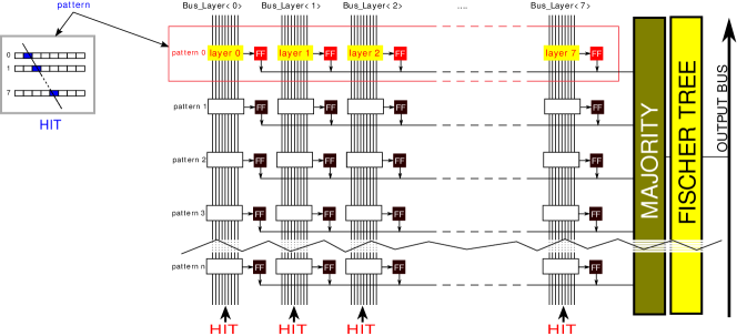
The pattern recognition is the heart of the FTK system, using a dedicated technology based on Content Addressable Memories (CAM), the AM chip AM2017 . There are 64 AM chips per AM board and a total of 128 AM boards in the full FTK system. Per chip, there are eight CAMS (one per detector layer), with 128K addresses each. Prior to data taking, the CAMs are loaded with predefined track patterns (pattern bank). The CAM data lines comprise 12 ordinary bits and three bits with ternary logic. Data (coarse resolution hit positions) arrive through 8 independent buses corresponding to the 8 detector layers. CAM matches are stored in Flip-Flops (FF), one per CAM and per address. A majority logic detects addresses where 7 or 8 CAMs have a match. The resulting addresses (road or pattern numbers) are read out using a Fisher tree. A schematic view of the AM chip is shown in Figure 3.
2.2 Track fitting
Track fits or track segment fits are based on a linearized model, where the helix parameters (, , , and ) are calculated as Annovi2013 :
| (1) |
The are the tracks parameters, the are the hit coordinates. There are two coordinates for pixel layers and one per SCT layer. The and are “fit constants” which are valid in small geometrical zones called “sectors“. The fit quality is also determined using another set of constants and a quadratic form. A FTK sector consists of a group of detector modules, one module per layer. Dedicated sets of fit constants are determined for each sector.
The full list of sectors with the corresponding fit constants is determined by processing about muon tracks with the ATLAS tracker simulation. The muon tracks are drawn from uniform distributions in the five track parameters, mm, mm, , and GeV-1. A single muon crossing a group of modules already defines a sector, however several muons in the same sector are required to evaluate the associated fit constants. There are of order sectors per region.
3 FTK patterns banks
3.1 TSP bank of pattern candidates
To prepare the pattern bank used for the pattern recognition, of order pattern candidates are generated (about per region). Each pattern candidate corresponds to eight coarse resolution hit positions, associated with a track. The eight hits correspond to the eight detector layers used for the pattern recognition. The tracks are drawn from uniform distributions in the five track parameters. The corresponding hit positions, however, are not obtained from a full simulation of the ATLAS tracker. Instead, the previously determined sectors and corresponding fit constants are used to predict hit positions. When generating the pattern candidates, duplicates are encountered. Only about one third of the patterns are unique, and duplicates with high multiplicity (coverage) are most important for the pattern recognition. The full set of unique pattern candidates, ordered by region, coverage and sector, is the so-called thin-space-pattern bank (TSP bank). In the following, the algorithm to select the patterns from these candidates for use with the AM boards is described.
3.2 AM pattern bank for use in the pattern recognition
The FTK hardware only supports a certain maximum number of pattern. There are two AUX boards per region, corresponding to ( million) patterns per region. As described above, three of the bits in each layer and each pattern are ternary. By setting a ternary bit to the state , the corresponding pattern is valid for two hit numbers in the respective layer. By setting a total number of bits across all eight layer to the state , the effective number of patterns stored in a single address increases to . The ternary bits thus can be used to vastly increase the number of patterns stored in the AM chip. On the other hand, patterns with a high number have a degraded spatial resolution and suffer from an increased rate of combinatorial background (fakes). A full set of patterns including ternary bits, determined for each of the regions, is termed “AM pattern bank”.
3.3 Packing pattern candidates to the AM pattern bank
For a single region, there are about pattern candidates. In this section the basic algorithm is described to select the most relevant patterns and pack them into the available million AM addresses, also making use of the available ternary bits.
The primary sorting criterion is the pattern coverage. Pattern candidates are ordered by their coverage, i.e. how often they have been generated. The AM addresses are filled with pattern candidates, starting with the highest coverage. Once all addresses are filled, there is no room to include further pattern candidates and the algorithm stops.
Using ternary bits, this algorithm is modified. The candidates are still processed in order of decreasing coverage. However, where possible, patterns are merged with previously stored patterns, using the ternary bits. This is illustrated in Figure 4.
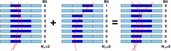
In the simplified example, shown for a single ternary bit per layer, the pattern shown in the middle with least-significant bits “00000011” is merged with a previously stored pattern “00XXX000”. The resulting pattern is “00XXX0XX”.
In order to be able to tune the algorithm, the number of ternary bits available for each layer can be chosen. In Figure 4, this number is set to one for each layer, while a maximum of three ternary bits is possible in hardware. A typical choice for the FTK system is to have one ternary bit per coordinate, i.e. two bits per pixel layer and one bit per SCT layer Annovi2013 . The disadvantage of this method is that some of the resulting patterns have a rather high number of bits in state “X” and thus are more susceptible to fakes.
Another method is to limit the number of ternary bits across the whole pattern, . While, for example, the maximum number of three ternary bits is allowed for each individual detector layer, the total number of ternary bits, summed across all layers, is limited to a fixed number, . Choose, for example, . The example shown in Figure 4 would lead to . So in that case the new pattern has to be stored at a new address, without merging. It turns out that this algorithm is best in trading efficiency against fake rate Stef2017 .
4 WildCards optimisation
To find a track in the FTK system, a pattern match is required in 7 or 8 layers. Owing to inevitable hardware failures, there are disabled modules, thus creating inefficiencies. Examples are shown in Figure 5 (left). The blue tracks cannot be reconstructed, because of disabled modules on the trajectory. Using realistic configurations of disabled hardware, FTK efficiency losses of order are observed in parts of the detector.
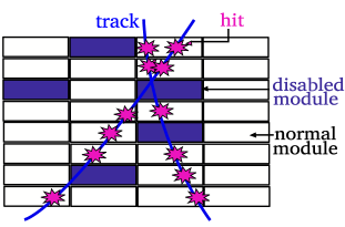
4.1 WildCards Algorithm
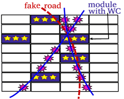
To recover the efficiency losses caused by disabled modules, a WildCard (WC) algorithm is used. In this algorithm, patterns which require hits on disabled module are modified such that they are recognized already if six out of the remaining seven possible hits are found. Figure 5 (right) illustrates the effect of the WC algorithm. The blue tracks are recovered. However, in addition a “fake road”, shown in red, is also found from combinatorial background. In other words, the WC algorithm does recover the efficiency but at the same time can lead to a much increased number of fake roads that endanger operation of the system due to congestion effects. The primary measure to control these effects is to limit the number of wildcards per pattern to one. In the unlikely case that there are two disabled modules for a given pattern, only one of them will have a wildcard set.
4.2 The wildcard penalty algorithm
To gain flexibility over the amount of fakes in the presence of wildcards, a WC penalty algorithm is introduced when selecting the pattern candidates for the AM pattern bank. The algorithm is designed such that it avoids to have wildcards and a large number of ternary bits in the same patterns. The original condition is modified by adding a penalty term
| (2) |
where is the penalty and is the number of wildcards in the pattern (i.e. zero or unity). The penalty forces patterns on which the WC algorithm is applied to have a lower maximum number of ternary bits in state "X".
4.3 Comparisons
To validate the performance and optimize the WC algorithm and WC penalty, different configurations are compared using the FTK simulation JAA2015 . In this study the maximum number of ternary bits () is set to seven for barrel regions () and to four for end-cap regions (). Five sets of pattern banks are investigated:
-
•
four banks produced with wildcards and , respectively;
-
•
a “nominal” bank produced without disabled modules or wildcards, corresponding to the ideal detector configuration.
When running the simulation with the nominal bank, there is the option to enable wildcards: list of disabled modules are defined with wildcards switched on. The result is expected to be similar to the case , although patterns can be packed more efficiently when knowing about disabled modules during bank production. Another option which can be tested with the nominal bank is to simply disable the modules, without using wildcards.
5 RESULTS
In Figure 7, efficiencies as a function of the muon pseudorapidity are compared for the seven configurations presented in section 4.3. The black line shows the simulation output assuming perfect detector conditions. When simulating disabled modules (green line), sizable inefficiencies are observed, in particular in those parts of the detector which suffer from the highest number of disabled modules. The efficiency improves significantly when using the WC algorithm (red line). The effect of producing dedicated pattern banks with wildcard and a penalty term in the range - is also shown. Increasing penalties reduce somewhat the efficiency, but even with the highest penalty studied, the efficiency is close to the ideal detector and superior to the case of disabled modules. In Figure 7, efficiencies are studied for the seven configurations, where averages are taken over ranges of polar angle. The configurations are labelled as: four settings of the penalty “WC_P0”,“WC_P1”,“WC_P2”,“WC_P3”; nominal bank with ideal detector “Ideal”; nominal bank with WC “WC_SIM”, nominal bank with disabled modules: “DM_SIM”. The ranges studies are: barrel , transition , endcap . The average over the full polar angular range is also shown. The overall efficiency is lowest in the endcap. The relative impact of dead modules is largest in the barrel, where the majority of the disabled modules are located. As expected, the nominal bank with wildcards and the simulation with have similar efficiencies.
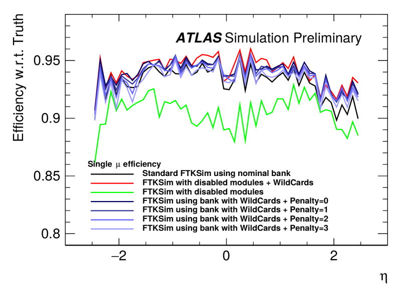
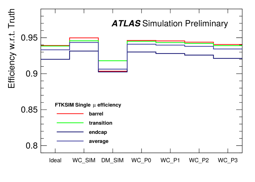
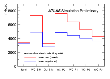

Figure 8 shows the number of roads (left) and the number of track fits (right), averaged over all events of a simulation of decays at a pileup of . The number of roads and the number of second stage track fits both serve as typical “dataflow” quantities, to quantify the danger of congestion effects in the FTK system. When comparing the nominal bank with and without dead modules “Ideal” and “DM_SIM”, there is only a small change in the dataflow. There is, however, a clear effect of the use of WC on the dataflow quantities. Switching on wildcards for the nominal bank causes the dataflow quantities to increase dramatically. When using dedicated pattern banks with penalties ranging from to , the increase can be controlled, although an increase in dataflow is present even for the highest penalty investigated.
6 CONCLUSION
The FTK is a hardware-based track finding system to be operated with the ATLAS trigger. It reconstructs all tracks of an event with transverse momentum GeV at a rate of kHz and a latency of for use in early stages of the high-level trigger decision.
Pattern recognition in the FTK is based on a predefined pattern bank. Only those tracks are reconstructed which have hits corresponding to seven out of eight possible layers in one of the predefined patterns. The patterns can be tuned in size by means of ternary logic.
Disabled modules are inevitable when operating a detector in the LHC environment. Using the nominal FTK pattern recognition algorithm, disabled modules cause track reconstruction inefficiencies of order -.
Wildcard algorithms are investigated in this article. When simply removing the disabled layers from the pattern recognition, the efficiency can be recovered, however at the cost of increasing the rate of combinatorial background. This effect endangers the operation of the FTK, which can only handle a certain average number of extra patterns or track fits per event. An algorithm is developed which dynamically reduces the pattern size in those parts of the pattern bank where wildcards are used. Simulations show that the algorithm can be useful to find a good compromise between excessive combinatorial background and the best possible efficiency.
References
- (1) The ATLAS TDAQ Collaboration 2016 JINST 11 P06008, Journal of Instrumentation Volume 11, (2016).
- (2) A. Annovi et al. ATLAS Fast TracKer (FTK) Technical Design Report (CERN-LHCC-2013-007, ATLAS-TDR-021, Geneva: CERN, 2013).
- (3) A. Annovi et al. 2017 JINST 12 C04013, Journal of Instrumentation Volume 12, (2017).
- (4) S. Schmitt, AM chip pattern recognition with optimized ternary bit usage (Connecting the dots, Orsay, France, 2017).
- (5) J. Adelman et al. Procedia Computer Science Volume 66, 540-545 (2015).