1024 \vgtccategoryResearch \vgtcpapertypeSystem \vgtcinsertpkg \shortauthortitleLukasczyk et al.: Cinema Darkroom
Cinema Darkroom:
A Deferred Rendering Framework for Large-Scale Datasets
Abstract
This paper presents a framework that fully leverages the advantages of a deferred rendering approach for the interactive visualization of large-scale datasets. Geometry buffers (G-Buffers) are generated and stored in situ, and shading is performed post hoc in an interactive image-based rendering front end. This decoupled framework has two major advantages. First, the G-Buffers only need to be computed and stored once—which corresponds to the most expensive part of the rendering pipeline. Second, the stored G-Buffers can later be consumed in an image-based rendering front end that enables users to interactively adjust various visualization parameters—such as the applied color map or the strength of ambient occlusion—where suitable choices are often not known a priori. This paper demonstrates the use of Cinema Darkroom on several real-world datasets, highlighting CD’s ability to effectively decouple the complexity and size of the dataset from its visualization.
keywords:
Deferred Rendering, Image Databases, In Situ Visualization, Post Hoc Analysis, Image-Based Shading.![[Uncaptioned image]](/html/2010.03936/assets/figures/teaser3.jpg)
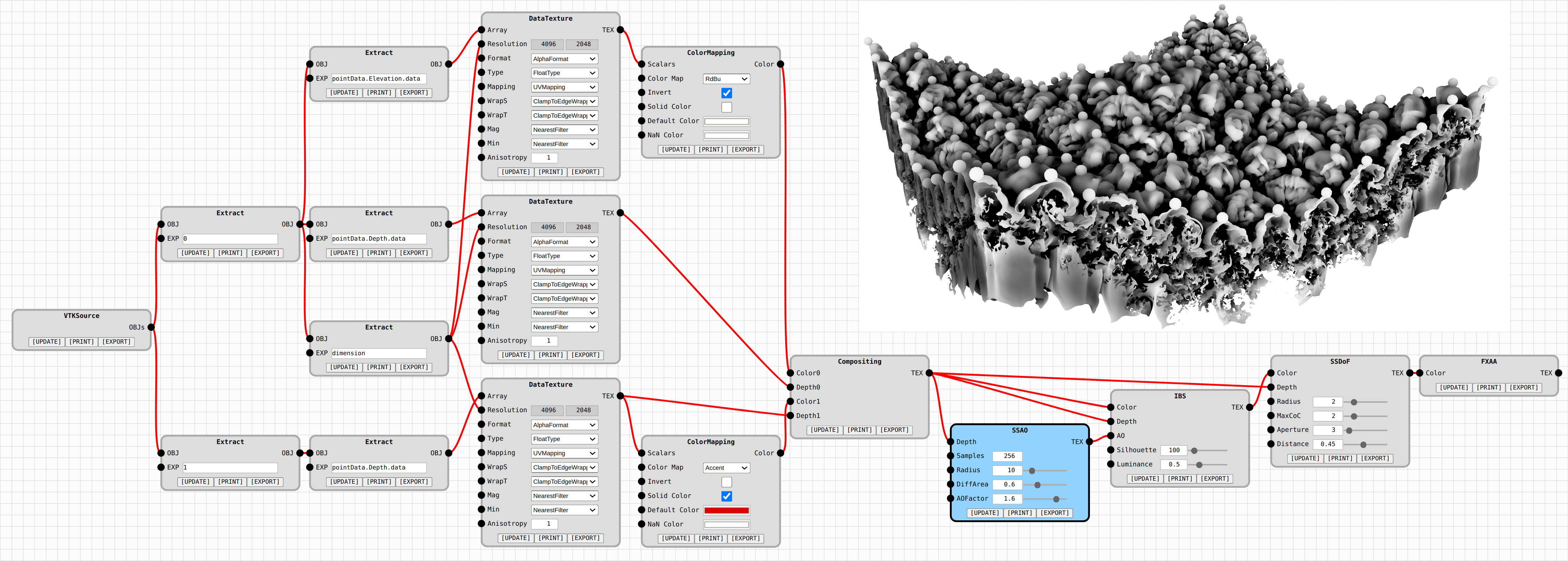
Post hoc Cinema Darkroom (CD) rendering of the Richtmyer-Meshkov Instability (RMI) dataset [23] showing a contour of the entropy field for isovalue colored by height (colored surface), as well as significant maxima of the height field (red spheres). RMI describes the impulsive acceleration of two fluids with different density, leading to the formation of an instability at the fluids’ interface [11]. The depicted scene consists of roughly million triangles, but CD utilizes a deferred rendering approach [12, 10] to interactively render the scene based only on a single depth image (for the contour) and a set of points (for the maxima). The depth image, the corresponding camera parameters, and the maxima coordinates have been computed and stored in situ in a Cinema database [3] via an extension of the Topology ToolKit (TTK) [38]. CD features a web-based deferred rendering front end (Fig. 1) that consumes these data products for post hoc visualization. Since the camera parameters are known, CD can compute the height field in image space and can correctly project spheres at the maxima locations. Moreover, CD supports many image-based rendering techniques; including post hoc color mapping [36], depth compositing [27], screen space ambient occlusion (SSAO) [35], screen space depth of field (SSDoF) [31], and fast approximate anti-aliasing (FXAA) [25].
Introduction
With the continuous increase in computational power, the I/O bandwidth bottleneck becomes the limiting factor for interactive data analysis and visualization. For instance, supercomputers are capable of simulating complex physical phenomena by performing floating operations per second, but bandwidth constraints still frequently prohibit storing every simulation state in its entirety for later exploration. This problem gave rise to various techniques that aim to compute and store analysis and visualization products while the simulation state still resides in machine memory. In particular, Ahrens et al. [3] propose to sample in situ the parameter space (isovalues, timesteps, …) and the visualization space (camera locations, clipping planes, …) via images, and then store them in a so-called Cinema database. Such a structured image database and can later be browsed post hoc along the sampling axes to emulate real-time visualization that is independent of the actual size and complexity of the depicted data. However, the resulting post hoc visualization is limited to the images stored in the Cinema database, and this approach requires foresight about many visualization parameters that are usually adjusted interactively (such as suitable transfer functions and lighting settings).
The concept of deferred rendering [12, 10] can overcome this issue by decoupling the information required for shading (e.g., depth buffers and scalar textures) from the shading itself (e.g., color mapping and lighting). In the context of in situ visualization, this concept can be used to only store the underlying shading information in the Cinema database, and postpone final shading to the post hoc exploration phase, at which point visualization parameters that were not known a priori can be interactively adjusted.
This paper describes Cinema Darkroom (CD): an open-source deferred rendering framework that enables high-fidelity post hoc visualization (Cinema Darkroom: A Deferred Rendering Framework for Large-Scale Datasets). CD follows the analogy of analog photography, where a scene is first captured on film and later developed in a darkroom; hence the name. CD consists of two components: a c++ module implemented in the Topology ToolKit (TTK) [38] that stores in situ the underlying shading information—collectively referred to as geometry buffers (G-Buffers)—in a Cinema database, and a web-based deferred rendering front end that enables analysts to interactively retrieve, compose, and shade G-Buffers through a flexible shading network (Fig. 1). This network consists of individual, interconnectable shading passes that feature various image-based rendering techniques (Sec. 2). As demonstrated in Sec. 3, CD is versatile, extendable, and compatible with existing tool chains designed for in situ visualization and analysis. To summarize, we make the following contributions:
-
•
We apply deferred rendering in the context of in situ visualization, where geometry buffers are stored in situ, and deferred shading is performed during post hoc exploration.
-
•
We describe the design and implementation of a flexible shading system that features a node-based workflow.
-
•
We illustrate the capabilities of CD via a variety of real-world examples, and show that image-based shading solely based on G-Buffers can be used for high-fidelity visualization.
1 Related Work
Ahrens et al. [3] proposed Cinema: the first image-based approach to extreme-scale in situ visualization and analysis. Their research is based on the rational that no matter how big the depicted dataset is, in the end visualization happens on a viewport with a fixed number of pixels. So to circumvent the bandwidth bottleneck, they propose to store, at simulation runtime, visualizations instead of the depicted datasets, since the visualizations are several magnitudes smaller than the data they are derived from. Specifically, they propose to sample the parameter space (isovalues, timesteps, etc.) and the visualization space (clipping planes, color maps, camera angles, etc.), and then generate for each sample a visualization that is uniquely identified by the sample values. This association enables analysts to later browse the resulting image database along the sampling axes, which emulates real-time data visualization of any size. Moreover, advanced Cinema front ends [27, 4] can use feature-centric queries to retrieve corresponding images.
However, Cinema requires foresight about suitable samplings, and post hoc visualization is limited to the elements in the database. To address these issues, O’Leary et al. [33] extended the initial concept of Cinema databases by instead of storing final visualizations, they propose to store geometry buffers (G-Buffers) [12, 10] that record general information of each pixel, such as the distance to the camera and the depicted scalar value. This approach enables post hoc color mapping, compositing, and shading, which not only increases flexibility during post hoc exploration, but also decreases the size of the image database. This concept of storing and processing G-Buffers is formalized in the latest Cinema specification [36].
We describe a system that fully utilizes G-Buffers stored in a Cinema database for high-fidelity post hoc visualization. In contrast to related work aimed at facilitating post hoc exploration on a conceptual level —such as the Explorable Images approach [39], Contour Tree Depth Images [8], or Space Time Volumetric Depth Images [17]— we aim to investigate how a flexible post hoc shading system can maximize the value of G-Buffer data stored in an in situ generated Cinema database. At heart, our system is based on a deferred rendering approach [10, 12] that feeds selected G-Buffers into a flexible shading architecture consisting of individual, interconnectable shading passes (Fig. 1). Such shading networks are commonly used in production tools like Blender [9] and Autodesk 3D Studio Max [20], or in game engines such as the Unity Engine [41] and the Unreal Engine [16]. To this end, CD features various deferred rendering-based shading techniques [36, 35, 26, 31, 27, 25] (Sec. 2.2). Moreover, due to its file system-based API, CD is compatible with existing frameworks designed for in situ database generation, such as ParaView Catalyst [5] and Alpine Ascent [24], as well as any other framework capable of writing out G-Buffers as files.
2 Cinema Darkroom (CD)
CD consists of a C++ module that handles G-Buffer generation, and a JavaScript-based deferred rendering front end for post hoc production visualization in the browser.
2.1 G-Buffer Database Generation
To generate G-Buffers, CD provides a new Visualization ToolKit (VTK) [37] filter called CinemaImaging that requires two inputs: 1) a dataset that is going to be depicted in form of a triangulation, and 2) a sampling grid storing camera locations and calibrations in form of a point cloud. The sampling grid can be specified manually [3] or automatically [28] based on the depicted dataset. The filter then generates geometry buffers for each sample point via an Embree-based raytracer [42]. By default, the filter stores in the G-Buffer the depth buffer (the distance to the camera), and a scalar buffer for each scalar field defined on the input dataset. As shown in Sec. 3, shading based on the depth buffers alone already provides good results, as 3D-world positions and surface normals can be accurately reconstructed in image-space, since the exact camera calibrations are known [28]. However, if desired, it is also possible to explicitly store position and normal vectors in the G-Buffers. Moreover, depending on the desired post hoc rendering effects, one can store additional information in the G-Buffers, such as true global illumination or motion blur.
Each resulting G-Buffer is stored in a Cinema database [36] (e.g., in vtkImageData format), which can be accessed by the web-based front end. Thus, every framework capable of writing out G-Buffers as files is compatible with the proposed workflow. For example, the G-Buffers used in Fig. 2 were stored in situ via a highly parallel raytracer [32] and the Ascent in situ framework [24].
2.2 Deferred Rendering Front End
Fig. 1 shows the web-based deferred rendering front end—written solely in client-side JavaScript and html—that consists of a graph-based pipeline editor and a render view that shows the output of a selected filter. The interface is modeled after established tools such as the material editor of Blender [9] and the pipeline editor of Inviwo [22]. Specifically, every filter used in the current pipeline is shown as a node, where its input and output parameters are shown as ports on the left and right side of the node, respectively. Additionally, the value of an input parameter can be controlled via a widget that is displayed on the right side of the port. If a filter requires the execution of shader code, then its input parameters are automatically passed to the vertex and fragment shaders as uniforms. The actual rendering is performed via Three.js [13] and WebGL [29], where input and output G-Buffers are stored as Framebuffer Objects. An output of one filter can be used as input of another filter, where the pipeline follows a push model. Thus, as soon as a new input value for a filter is available, the filter updates its output, which then triggers an update of filters that use the updated output as an input, and so forth. Output ports can be connected to input ports via drag an drop, where established connections are shown via red edges.
Besides multipurpose filters used for data transformations, CD currently features the following image-based rendering techniques:
-
ColorMapping
Post Hoc Color Mapping [36];
-
Compositing
Depth Image Based Compositing [27];
-
SSAO
Screen Space Ambient Occlusion [35];
-
SSDD
Screen Space Depth Darkening [26];
-
SSDoF
Screen Space Depth of Field [31];
-
IBS
Image-Based Silhouettes [27]; and
-
FXAA
Fast Approximate Anti-Aliasing [25].
New filters can be added to CD with minimal overhead. To add a filter, developers just needs to 1) inherit form the abstract filter class, 2) define input and output parameters, and 3) provide the code that transforms input to output parameters (e.g., shader code).
3 Results
This section demonstrates on several real-world datasets the versatility and flexibility of CD, where the context of the presented visualizations are reported in the captions of Figures 3-7.
It is important to note that all presented visualizations are solely shaded based on depth buffers (to approximate lighting) and scalar images (for color mapping). So no actual lighting information is stored in the corresponding Cinema databases. Thus, the most significant filter that impacts visual quality is Screen Space Ambient Occlusion (SSAO) [35] (or alternatively Screen Space Depth Darkening (SSDD) [26]) as it approximates global illumination. Input parameters of this filter control the sample number and the sampling radius to approximate the local neighborhood of each pixel, where small radii tend to produce sharp shadows, while large radii produce soft shadows (Fig. 3). The number of samples then controls the quality of the approximation. The pipeline editor makes it possible to interactively search for suitable parameters, and to combine multiple SSAO filters to approximate shadows at different scales (Fig. 4).
The SSAO technique implemented in CD works well in all presented case studies, except for the particle visualization shown in Fig. 5, since the current implementation is designed to approximate shadows on surface-like structures. This technique still produces good results for the visualization of streamlines (Figs. 3-4) and jagged surfaces (Fig. 6), but causes visual artifacts for highly discontinuous depth buffers which are prominent in particle visualizations. This limitation can be addressed by adding SSAO techniques that are optimized for such visualizations [15, 19, 14].
4 Conclusion
This paper described Cinema Darkroom (CD): an interactive deferred rendering framework for high-fidelity post hoc visualization. As demonstrated on several real-world examples (Sec. 3), CD is versatile, flexible, and compatible with existing tool chains designed for in situ visualization and analysis.
However, CD is currently limited to G-Buffers that depict fully opaque geometry. This notably excludes post hoc volume rendering (except in its most basic form of directly storing color images in situ). To address this issue, other techniques such as the Explorable Images approach [39] or generative models [7] need to be investigated if they can be integrated in a deferred rendering pipeline. Finally, CD is designed to be easily extendable and we plan to include in future work more image-based shading techniques such as Image-Space Line Integral Convolution [21], Scalable Ambient Obscurance [30], and SSAO optimized for particle visualization [15, 19, 14].
Acknowledgments
This work was supported by the U.S. Department of Homeland Security under Grant Award 2017-ST-061-QA0001 and 17STQAC00001-03-03, and the National Science Foundation Program under Award No. 1350573. The views and conclusions contained in this document are those of the authors and should not be interpreted as necessarily representing the official policies, either expressed or implied, of the U.S. Department of Homeland Security. This work was also partially supported by the German research foundation (DFG) through the IRTG 2057, and by a grant from the Swedish Foundation for Strategic Research (SSF, BD15-0082), the SeRC (Swedish e-Science Research Center) and the ELLIIT environment for strategic research in Sweden.
References
-
[1]
BLAST: High-Order Finite Element Hydrodynamics, 2020.
https://computing.llnl.gov/projects/blast. -
[2]
Devil Ray: High-Order Ray Tracer, 2020.
https://github.com/LLNL/devil_ray. - [3] J. Ahrens, S. Jourdain, P. O’Leary, J. Patchett, D. Rogers, and M. Petersen. An Image-Based Approach to Extreme Scale In Situ Visualization and Analysis. In Proceedings of the International Conference for High Performance Computing, Networking, Storage and Analysis, pp. 424–434, 2014.
- [4] G. Aldrich, J. Lukasczyk, J. D. Hyman, G. Srinivasan, H. Viswanathan, C. Garth, H. Leitte, J. P. Ahrens, and B. Hamann. A Query-Based Framework for Searching, Sorting, and Exploring Data Ensembles. Computing in Science & Engineering, 22(2):64–76, 2019.
- [5] U. Ayachit, A. Bauer, B. Geveci, P. O’Leary, K. Moreland, N. Fabian, and J. Mauldin. Paraview Catalyst: Enabling In Situ Data Analysis and Visualization. In Proceedings of the First Workshop on In Situ Infrastructures for Enabling Extreme-Scale Analysis and Visualization, pp. 25–29, 2015.
- [6] P. D. Bello-Maldonado, T. V. Kolev, R. N. Rieben, and V. Z. Tomov. A Matrix-Free Hyperviscosity Formulation for High-Order ALE Hydrodynamics. Computers & Fluids, p. 104577, 2020.
- [7] M. Berger, J. Li, and J. A. Levine. A generative Model for Volume Rendering. IEEE transactions on visualization and computer graphics, 25(4):1636–1650, 2018.
- [8] T. Biedert and C. Garth. Contour Tree Depth Images for Large Data Visualization. In Proceedings of the 15th Eurographics Symposium on Parallel Graphics and Visualization, pp. 77–86, 2015.
- [9] Blender Online Community. Blender - A 3D Modelling and Rendering Package. 2018. http://www.blender.org.
- [10] Bor-Sung Liang, Wen-Chang Yeh, Yuan-Chung Lee, and Chein-Wei Jen. Deferred Lighting: A Computation-Efficient Approach for Real-Time 3-D Graphics. In 2000 IEEE International Symposium on Circuits and Systems (ISCAS), vol. 4, pp. 657–660 vol.4, 2000.
- [11] R. H. Cohen, W. P. Dannevik, A. M. Dimits, D. E. Eliason, A. A. Mirin, Y. Zhou, D. H. Porter, and P. R. Woodward. Three-Dimensional Simulation of a Richtmyer–Meshkov Instability with a Two-Scale Initial Perturbation. Physics of Fluids, 14(10):3692–3709, 2002.
- [12] M. Deering, S. Winner, B. Schediwy, C. Duffy, and N. Hunt. The Triangle Processor and Normal Vector Shader: A VLSI System for High Performance Graphics. ACM Siggraph computer graphics, 22(4):21–30, 1988.
- [13] J. Dirksen. Learning Three.js: The JavaScript 3D Library for WebGL. Packt Publishing Ltd, 2013.
- [14] S. Eichelbaum, G. Scheuermann, and M. Hlawitschka. PointAO-Improved Ambient Occlusion for Point-based Visualization. In EuroVis (Short Papers), 2013.
- [15] W. Engelke, K. Lawonn, B. Preim, and I. Hotz. Autonomous Particles for Interactive Flow Visualization. In Computer Graphics Forum, vol. 38, pp. 248–259. Wiley Online Library, 2019.
- [16] Epic Games. Unreal Engine, 2020. https://www.unrealengine.com.
- [17] O. Fernandes, S. Frey, F. Sadlo, and T. Ertl. Space-time volumetric depth images for in-situ visualization. In Proceedings of IEEE 4th Symposium on Large Data Analysis and Visualization (LDAV), pp. 59–65, 2014.
- [18] C. Garth. Simulation of a Jet Flow, 2020. doi: 10 . 21227/qjxp-kc31
- [19] S. Grottel, M. Krone, C. Müller, G. Reina, and T. Ertl. MegaMol—A Prototyping Framework for Particle-Based Visualization. IEEE transactions on visualization and computer graphics, 21(2):201–214, 2014.
- [20] J. Harper. Mastering Autodesk 3ds Max. John Wiley & Sons, 2012.
- [21] J. Huang, W. Pei, C. Wen, G. Chen, W. Chen, and H. Bao. Output-Coherent Image-Space LIC for Surface Flow Visualization. In 2012 IEEE Pacific Visualization Symposium, pp. 137–144, 2012.
- [22] D. Jönsson, P. Steneteg, E. Sundén, R. Englund, S. Kottravel, M. Falk, A. Ynnerman, I. Hotz, and T. Ropinski. Inviwo-A Visualization System with Usage Abstraction Levels. IEEE transactions on visualization and computer graphics, 2019.
-
[23]
P. Klacansky.
Open Scientific Visualization Datasets, 2020.
https://klacansky.com/open-scivis-datasets/. - [24] M. Larsen, J. Ahrens, U. Ayachit, E. Brugger, H. Childs, B. Geveci, and C. Harrison. The alpine in situ infrastructure: Ascending from the ashes of strawman. In Proceedings of the In Situ Infrastructures on Enabling Extreme-Scale Analysis and Visualization, pp. 42–46. 2017.
- [25] T. Lottes. Fast Approximate Anti-Aliasing (FXAA). NVIDIA Corporation, Santa Clara, CA, USA, Feb, 2009.
- [26] T. Luft, C. Colditz, and O. Deussen. Image Enhancement by Unsharp Masking the Depth Buffer, vol. 25. ACM, 2006.
- [27] J. Lukasczyk, C. Garth, G. H. Weber, T. Biedert, R. Maciejewski, and H. Leitte. Dynamic Nested Tracking Graphs. IEEE Transactions on Visualization and Computer Graphics, 26(1):249–258, 2020.
- [28] J. Lukasczyk, E. Kinner, J. Ahrens, H. Leitte, and C. Garth. VOIDGA: A View-Approximation Oriented Image Database Generation Approach. In IEEE 8th Symposium on Large Data Analysis and Visualization (LDAV), 2018.
- [29] C. Marrin. Webgl Specification. Khronos WebGL Working Group, 2011. https://www.khronos.org/registry/webgl/specs/latest/1.0/.
- [30] M. McGuire, M. Mara, and D. P. Luebke. Scalable ambient obscurance. In High Performance Graphics, pp. 97–103. Citeseer, 2012.
- [31] L. McIntosh, B. E. Riecke, and S. DiPaola. Efficiently simulating the bokeh of polygonal apertures in a post-process depth of field shader. In Computer Graphics Forum, vol. 31, pp. 1810–1822. Wiley Online Library, 2012.
- [32] K. Moreland, C. Sewell, W. Usher, L.-t. Lo, J. Meredith, D. Pugmire, J. Kress, H. Schroots, K.-L. Ma, H. Childs, et al. VTK-m: Accelerating the Visualization Toolkit for Massively Threaded Architectures. IEEE computer graphics and applications, 36(3):48–58, 2016.
- [33] P. O’Leary, J. Ahrens, S. Jourdain, S. Wittenburg, D. H. Rogers, and M. Petersen. Cinema Image-Based In Situ Analysis and Visualization of MPAS-Ocean Simulations. Parallel Computing, 55:43–48, 2016.
- [34] S. Popinet. Gerris: A Tree-Based Adaptive Solver for the Incompressible Euler Equations in Complex Geometries. Journal of Computational Physics, 190(2):572–600, 2003. http://gfs.sf.net/.
- [35] T. Ritschel, T. Grosch, and H.-P. Seidel. Approximating Dynamic Global Illumination in Image Space. In Proceedings of the 2009 Symposium on Interactive 3D Graphics and Games, pp. 75–82, 2009.
- [36] D. Rogers, J. Woodring, J. Ahrens, J. Patchett, and J. Lukasczyk. Cinema Database Specification - Dietrich Release v1.2. Technical Report LA-UR-17-25072, Los Alamos National Laboratory, 2018.
- [37] W. J. Schroeder, K. Martin, and W. E. Lorensen. The Visualization Toolkit: An Object Oriented Approach to 3D Graphics. Kitware, Inc., 2004.
- [38] J. Tierny, G. Favelier, J. A. Levine, C. Gueunet, and M. Michaux. The Topology ToolKit. IEEE Transactions on Visualization and Computer Graphics, 2017. https://topology-tool-kit.github.io/.
- [39] A. Tikhonova, C. D. Correa, and K. Ma. Explorable Images for Visualizing Volume Data. In 2010 IEEE Pacific Visualization Symposium (PacificVis), pp. 177–184, 2010.
-
[40]
TTK Contributers.
TTK Data Repository, 2020.
https://github.com/topology-tool-kit/ttk-data. - [41] Unity Technologies. Unity Game Engine. 2020. https://unity.com.
- [42] I. Wald, S. Woop, C. Benthin, G. S. Johnson, and M. Ernst. Embree: A Kernel Framework for Efficient CPU Ray Tracing. ACM Trans. Graph., 33(4), July 2014.
- [43] T. Weinkauf and H. Theisel. Streak Lines as Tangent Curves of a Derived Vector Field. IEEE Transactions on Visualization and Computer Graphics (Proceedings Visualization 2010), 16(6):1225–1234, 2010.