The deployment of the ICARUS LAr detector on the short baseline (SBN) neutrino beam at FNAL
Abstract
The Icarus T600 detector represents the first example of a fully working large-mass LAr detector. After operations at the LNGS INFN laboratories, it has been refurbished at CERN in 2015-2017 and then installed as far detector on the BNB neutrino beamline at FNAL. The main operations involved in the T600 overhauling are thouroghly described in this paper.
Introduction
The ICARUS T600 detector is made of two identical modules for a total mass of 760 tons of Liquid Argon, representing the biggest detector of this kind in operation. Each module is equipped with two readout chambers on the long sides, with planes of wires at 0∘, 60∘ for a total of 54000 readout wires. ICARUS T600 has been previously installed in the underground INFN-LNGS Gran Sasso Laboratory and has been the first large-mass LAr TPC operating as a continuously sensitive general purpose observatory [1]. The operation of the ICARUS T600 LAr TPC demonstrated the enormous potential of this detection technique, addressing a wide physics program with the simultaneous exposure to the CNGS neutrino beam and cosmic rays. The ICARUS T600 detector is currently being deployed at FNAL as a far detector of the Short-Baseline Neutrino (SBN) program [2], dedicated to clarify the sterile neutrino anomalies by precisely and independently measuring both appearance and disappearance in the FNAL Booster Neutrino Beam (BNB).
The CERN overhauling phase
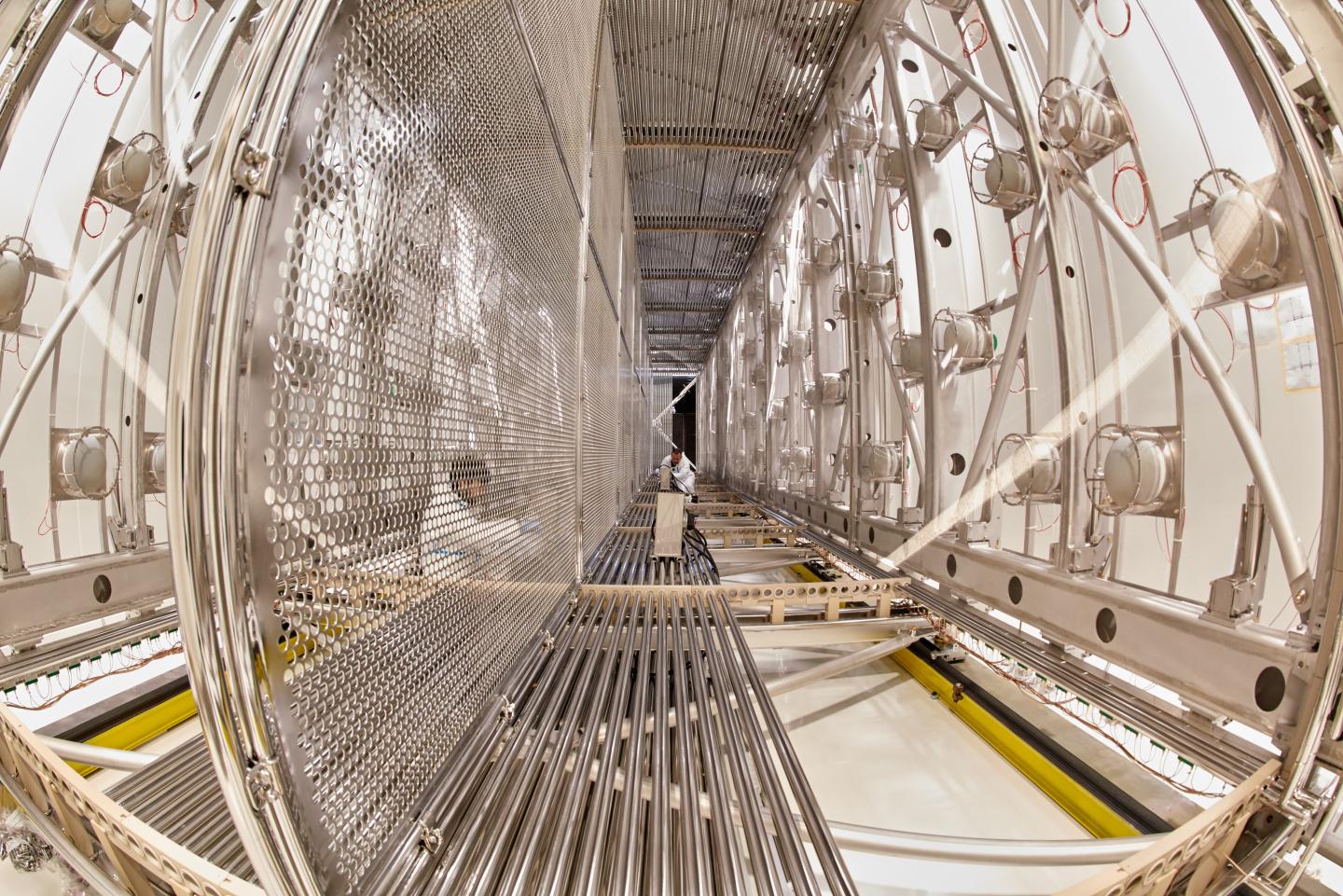
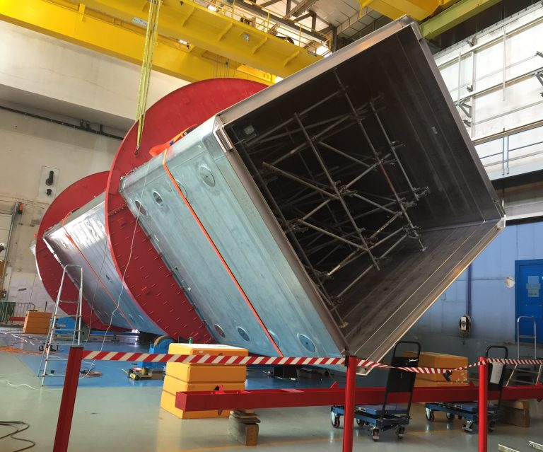
Having to face a more severe experimental condition than at the LNGS underground site, due to the presence of a 11 kHz cosmic rays background, the ICARUS T600 detector underwent an intensive overhauling at CERN in the Neutrino Platform framework from 2015 to 2017, before being shipped to FNAL. Several improvements were introduced, while maintaining the already achieved good performance obtained during the LNGS run:
-
•
new cold vessels, with a purely passive insulation;
-
•
renovated LAr cryogenics/purification equipment;
-
•
improvement of the cathode planarity;
-
•
upgrade of the light scintillation detection (PMT) system with higher granularity and a time resolution around 1 ns;
-
•
new faster, higher-performance read-out electronics for the wire chambers.
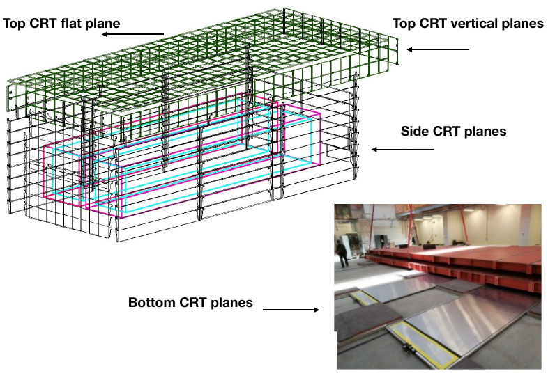
To handle the large flux of cosmic rays, a 3 m concrete overburden to remove contribution from charged hadrons/’s and a 4 external Cosmic Ray Tagger (CRT) to correlate residual muons with TPC signals were introduced in addition to the PMT system. Some pictures of the above improvements and the overhauling phase at CERN are shown in figure 1.
The ICARUS deployment at Fermilab
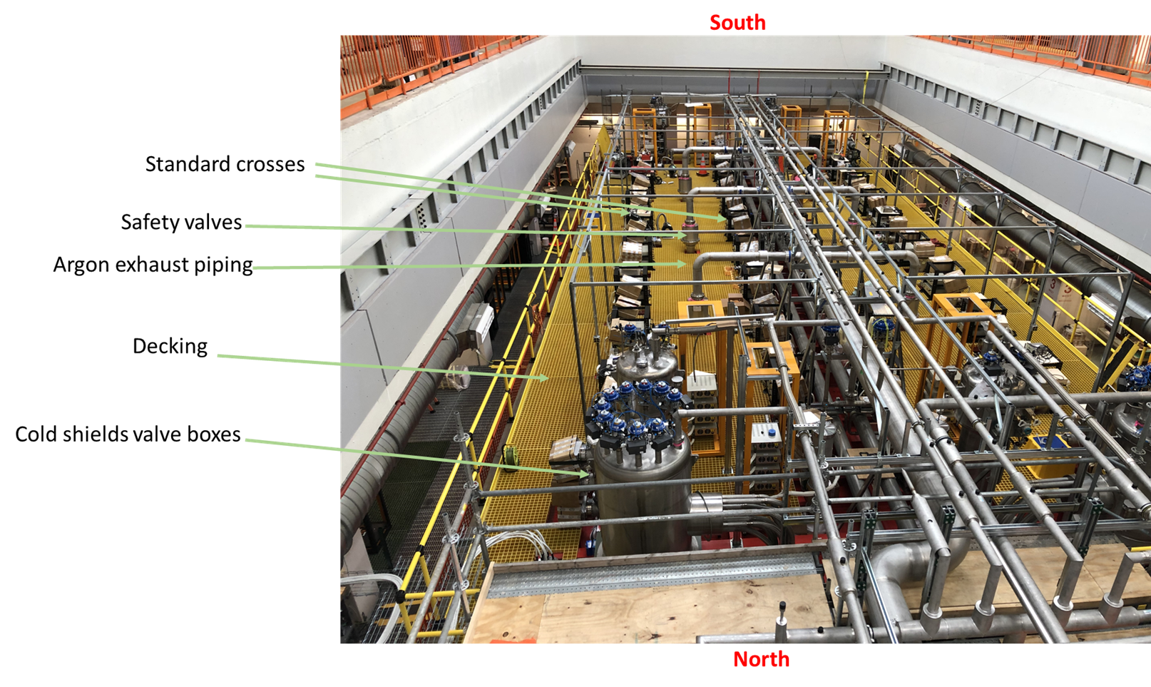
ICARUS modules were placed inside the warm vessel in August 2018 after their shipping to FNAL in 2017. Installation of the TPC and PMT feed-through flanges and connectivity tests were completed by February 2019. In sequence leak tightness tests were then performed and top cold shields and top CRT support have been installed. Side CRT installation is also ongoing. The installation of proximity cryogenics started in February 2019 and is almost completed. Evacuation of the detector started on June 2019 to reach a residual internal pressure of 10-4 mbar.
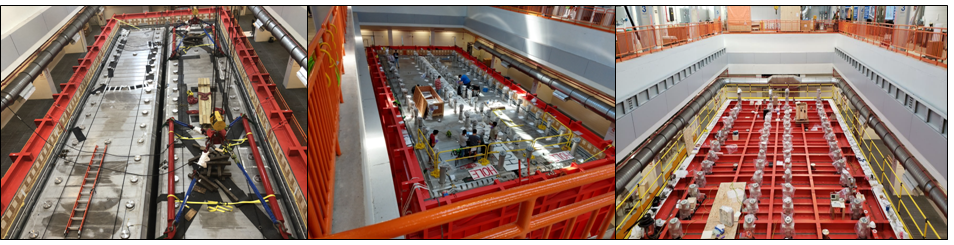
Some pictures related to these deployment operations at FNAL are shown in Figure 2, while the present status of the cryogenic plant is shown in figure 3.
The new Icarus light detection system.
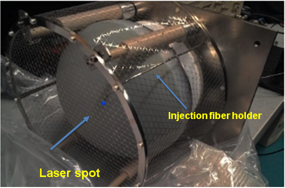
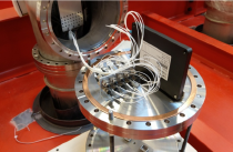
Scintillation in LAr is characterized by a prompt photon emission in the VUV region at nm with a yield ’s/MeV. Detection is done through large area 8“ PMTs with a TPB coated glass window, acting as a wavelength shifter to the PMT photocathode sensitive region. The new light collection system will allow to precisely identify the time of occurrence () of any ionizing event in the ICARUS TPCs, determine the event rough topology for selection purposes and generate a trigger signal for read-out. The PMT system exploits 90 8" Hamamatsu R5912-MOD PMTs per TPC (5% coverage, 15 phe/MeV) providing sensitivity to low energy events ( 100 MeV), good spatial resolution ( 50 cm) and ns timing resolution [3]. The readout is via CAEN V1730B digitizers (500 Ms/s, 14 bit, 2 Vpp dynamic range). The time evolution of the PMT timing/gain equalization will be traced by using fast light pulses from a Hamamatsu PLP10 diode laser source (FWHM 60 ps, 405 nm, 120 mW power). Laser pulse are sent to each PMT via a distribution system based on an Agiltron optical switch (1x46, only 36 channels used) connected to 36 20 m long multimode (MM) 50 m core fiber patch cords from OZ/Optics, going to 36 CF40 to CF200 adapters holding each one an optical feedthrough from Vacom Gmbh. Each adapter is equipped with one fused fibers optical splitter from Lightel US on the internal side. Inside the cryostat 7 m long optical injection fibers connected to the output pigtails of the splitters convey the light in front of each PMT. A picture of the injection fiber holder in front of one PMT and of one CF40 to CF200 adapter is shown in figure 4.
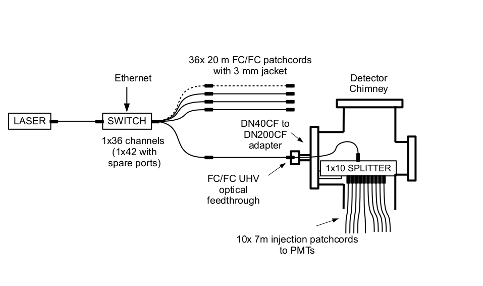
The layout of the calibration system is shown in figure 5. In addition the system will include also a fast photodiode (Thorlabs DET02AFC) for monitoring the laser stability and a remotely controlled system to attenuate the input laser power to the delivery system.
All PMTs and calibration system components parts were individually tested. In particular:
-
•
All PMTs were tested at room temperature in a dedicated dark room at CERN. A subset of 60 PMTs tested was immersed in LAr to compare the PMT performance in cryogenic environment to room temperature;
- •
-
•
the laser diode and the optical switch stabilities were tested over a period of many months.
All 108 feed-through flanges (36 for PMT HV, 36 for PMT signal and 36 for optical fibers) were installed from December 2018 to February 2019.
First results on the ICARUS wire read-out
The new ICARUS TPC electronics [6] has a front-end based on analogue low noise/charge sensitive pre-amplifiers, a serial 12 bit ADC, one per channel with 400 ns sync. sampling and a serial bus architecture with optical links for Gigabit/s transmission. Analogue/digital electronics is directly mounted on the signal feedthrough flanges: the external side of flange itself is the back-plane for a custom mini-crate, see figure 6 for some details. The read-out is performed by nine CAEN A2795 boards per chimney housed in a mini-crate serving 576 channels. Each board hosts 64 pre-amplifiers, 64 12 bit, 2.5 Ms/s ADCs, FPGA, memory and optical link interface. From the output of the preamplifier, the board operates as a waveform digitizer. The back-plane of a mini-crate distributes power supply and local control signals. All feed-through flanges and mini-crates with the TPC wire read-out electronics (576 channels + optical links) have been installed. A successful test of the full readout chain, from wires to DAQ, was performed in April/May 2019 for all the mini-crates.
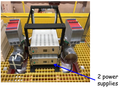
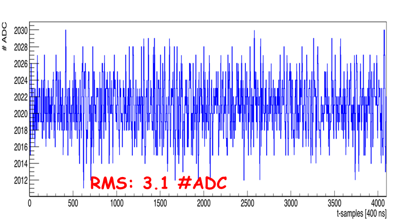
An example of the noise determination for wires is shown in the right panel of figure 6.
Conclusions
The Icarus T600 detector is being installed at Fermilab, as Far Detector on the BNB beamline. It has been successfully upgraded at Cern, within the WA104 project framework and will be soon ready for data taking at Fermilab.
References
- [1] C. Rubbia et al. (ICARUS Collaboration), JINST 6 2011 (P07011).
- [2] R. Acciari et al., A Proposal for a Three Detector Short-Baseline Neutrino Oscillation Program in the Fermilab Booster Neutrino Beam, arXiv:1503.01520.
- [3] M. Babicz et al., JINST 13 2018 (P10030).
- [4] M. Bonesini et al., Nucl. Instr. Meth. A936 261-262 (2019).
- [5] R.Bertoni, M. Bonesini, A. de Bari, M. Rossella, JINST 11 (2016) no.05, P05024
- [6] L. Bagby et al., JINST 13 2018 (P12007).