The FAMU experiment at RIKEN RAL for a precise measure of the proton radius
Abstract:
The goal of the FAMU experiment at RIKEN RAL is the measure of the hyperfine splitting of the ground state of the muonic hydrogen, to allow a determination of the proton Zemach radius with a precision better than . The comparison of this measurement with the ones done with ordinary hydrogen may help to solve the so-called “proton radius puzzle” , triggered by the discrepancy in the proton charge radius value as extracted from muonic Lamb shift and the value based on e-p scattering and ordinary hydrogen spectroscopy.
1 Introduction
Many properties of the proton, such as its radius and anomalous magnetic moment, are not completely understood. The so-called proton radius “puzzle” [1] refers to the discrepancy between the electron and muon determination of the proton charge radius. This discrepancy may be due to a violation of the electron-muon universality or simply to not well understood experimental systematic errors.
The FAMU (Fisica degli Atomi Muonici) experiment aims at the measurement of with a relative accuracy better than [2, 3, 4]. It makes use of a high intensity pulsed low-energy muon beam, stopping in a hydrogen target, to produce muonic hydrogen (in a mixture of singlet F=0 and triplet F=1 states) and a tunable mid-IR (MIR) pulsed high power laser to excite the hyperfine splitting (HFS) transition of the 1S muonic hydrogen (from F=0 to F=1 states). Exploiting the muon transfer from muonic hydrogen to another higher-Z gas in the target (such as or Ar), the HFS transition will be recognized by an increase of the number of X-rays from the cascade, while tuning the laser frequency (). From the measure of the Zemach radius of the proton may be deduced with a precision up to , thus sheding new light on the problem of the proton radius puzzle.
The FAMU experiment is being performed in steps, starting from the study of the transfer rate from muonic hydrogen to another higher-Z gas and ending with the full working setup with the pump MIR laser and a multipass optical cavity to determine the proton Zemach radius. The preliminary steps have allowed to determine the best mixture to be used inside the cryogenic target and optimize the operating conditions.
2 Experimental layout at RIKEN-RAL
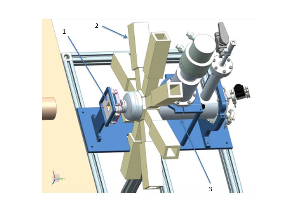
The setup for the preliminary 2015-2016 (R582) FAMU data taking is schematically shown in figure 1 and fully described in reference [5]. It includes a beam hodoscope to characterize the impinging muon beam, a cryogenic target and detectors to see the characteristic low energy X-rays emitted in the process under study.
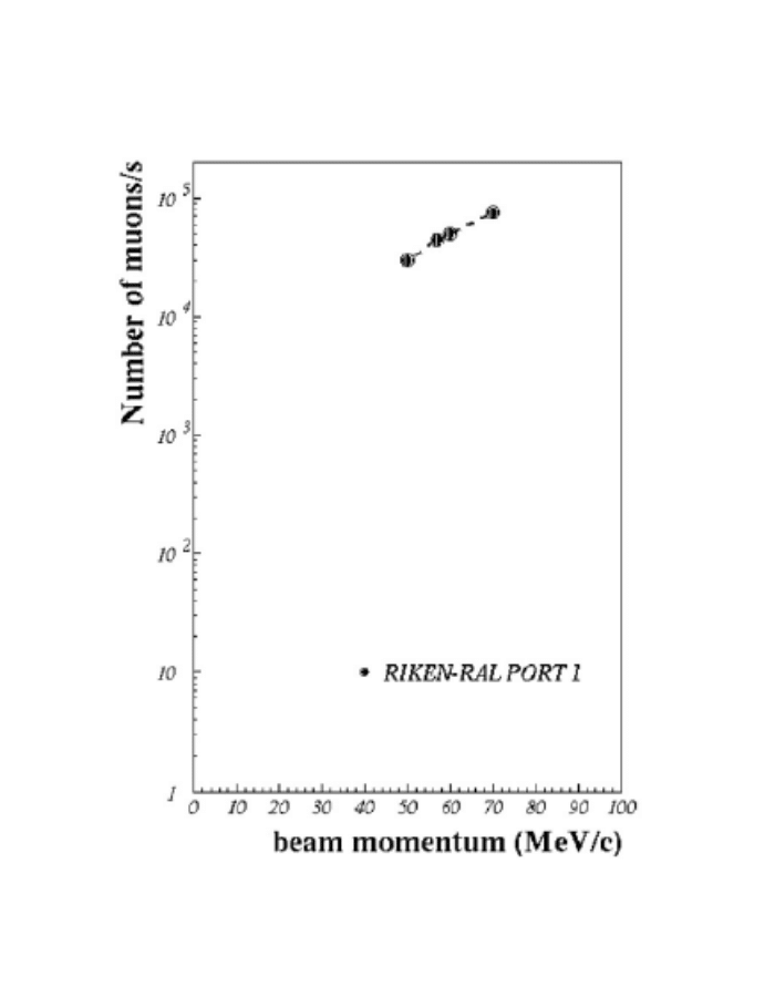
Data have been taken at the RIKEN-RAL muon facility[6], where the ISIS primary proton beam at 800 MeV/c produces a high-intensity pulsed muon beam, impinging on a secondary carbon target. The experiment makes use of a decay muon beam at MeV/c. The beam has a double pulse structure (70 ns FWHM widths, 320 ns peak to peak distance ) reflecting the primary beam structure. With an intensity of the beam has a momentum spread and an angular divergence mrad.
2.1 Beam characterization
To monitor the beam parameters,
avoid any undetected drift in beam shape and position and center the
target a beam hodoscope system is needed.
The beam hodoscope system has allowed to: tune the incoming beam, deliver timing information, as respect to radiofrequency, for DAQ readout and trigger, and monitor the intensity of each beam pulse. The system is based on three hodoscopes.
Two of them are removable X/Y beam hodoscopes, made
of 2 planes of 32 33 mm2 square scintillating Bicron BCF12 fibers
read at alternating fibers’ ends by Hamamatsu S12572 silicon photomultiplier (SiPM),
with 25 m cells
[7, 8].
They have a 1010 cm2 active area.
The third one
makes use of 1 mm square BCF12 fibers, with white EMA coating, to
ensure light tightness, read by 1 mm RGB Advansid SiPM,
with 40 m cells [8, 9] and has
an active area of 3.2 3.2 cm2. It was permanently installed
in front of the beam target window during data taking.
As SiPM output signals are sizeable - 40 mV with a S/B 10 - no
amplification stage is needed. They are digitized by CAEN V1742 FADCs (5 Gb/s, 12 bits, 1 Vpp dynamic range), providing information on timing, integrated charge and pulse height.
The gain drift of SiPM with temperature will be controlled by CAEN DT5485
digital power supplies with built-in feedback on temperature,
measured by Analog Devices TMP37 thermistors with a precision.
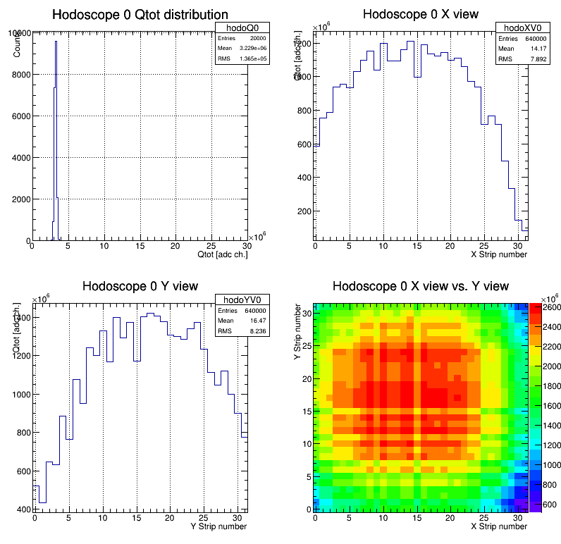
A X/Y beam profile, as measured at Port 1, is shown in the left panel of figure 2. A rms beam width less than 10 mm in both directions (X,Y) is measured.
The total collected charge from the two planes of a detector ()
may be used, after a suitable calibration 111the calibration procedure
makes use of
laboratory test data taken with cosmic muons and tabulated values of dE/dx vs
momentum from PDG, to estimate the incoming muon rate, as shown in the
right panel of figure 2.
To reduce the amount of material in front of the target a
new hodoscope, based on 0.5 0.5 mm2 square Bicron BCF12
scintillating fibers
read by 11 mm2 Hamamatsu S12751-050P SiPM will replace the current
1 mm pitch one in the final FAMU data taking. With 32+32 X,Y channels it will cover an active are of about 7.2 7.2 cm2, to match the area of the new target entrance window.
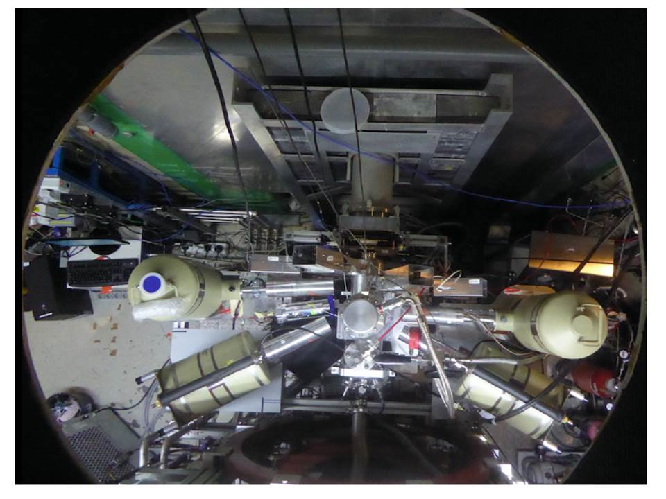
2.2 X-rays detection
To extract the muonic X-ray lines of interest ( at 100-200 keV) with the best energy resolution and minimal events pile-up, hygroscopic LaBr3:Ce crystals were used 222 A preliminary study to asses if non-hygroscopic crystals, such as PrLuAg and Ce:GAAG, may be suitable was done and is reported in reference [10]. In addition HpGe detectors (up to four were used at the same time) completed the experimental setup. They were used as a cross-reference due to their much better energy resolution. Their readout was performed through CAEN V1724 digitizers (14 bit, 100 MS/s, 10 Vpp dynamic range). Detectors were placed around the region of maximal density of muonic hydrogen formation.
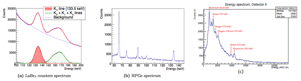
The main X-rays detector is based on eight one inch diameter, one inch length LaBr3:Ce crystals arranged in a crown, read by Hamamatsu R112265-200 UBA 1” photomultipliers tube equipped with an active high voltage divider and a Digital Pulse Processor (DPP) [11]. Up to now, data have been acquired and processed by CAEN V1730 digiters (14 bit, 500 MS/s, 2 Vpp dynamic range) in the framework of the general FAMU Data Acquisition System [12].
The collaboration has also developed a complementary read-out system for the LaBr3:Ce crystals based on SiPM arrays. The advantage of the PMT readout as respect to SiPM readout of a better rise time (10 ns as compared to 20 ns) is balanced, as regards the noise, by the use of smaller crystal size: 1/2” instead of 1”. Eight 1/2” LaBr with SiPM array readout have been recently tested and were used, due to their compact size, to instrument the most inaccessible regions around the target[5, 13, 14]. The readout was based on 44 array of 33 mm2 Hamamatsu S13361 TSV SiPM. The output signals are summed up on a custom made PCB and digitized by CAEN V1730 digitizers. No amplification is needed, since the signal is about 100-200 mV.
3 Experimental results on the transfer function
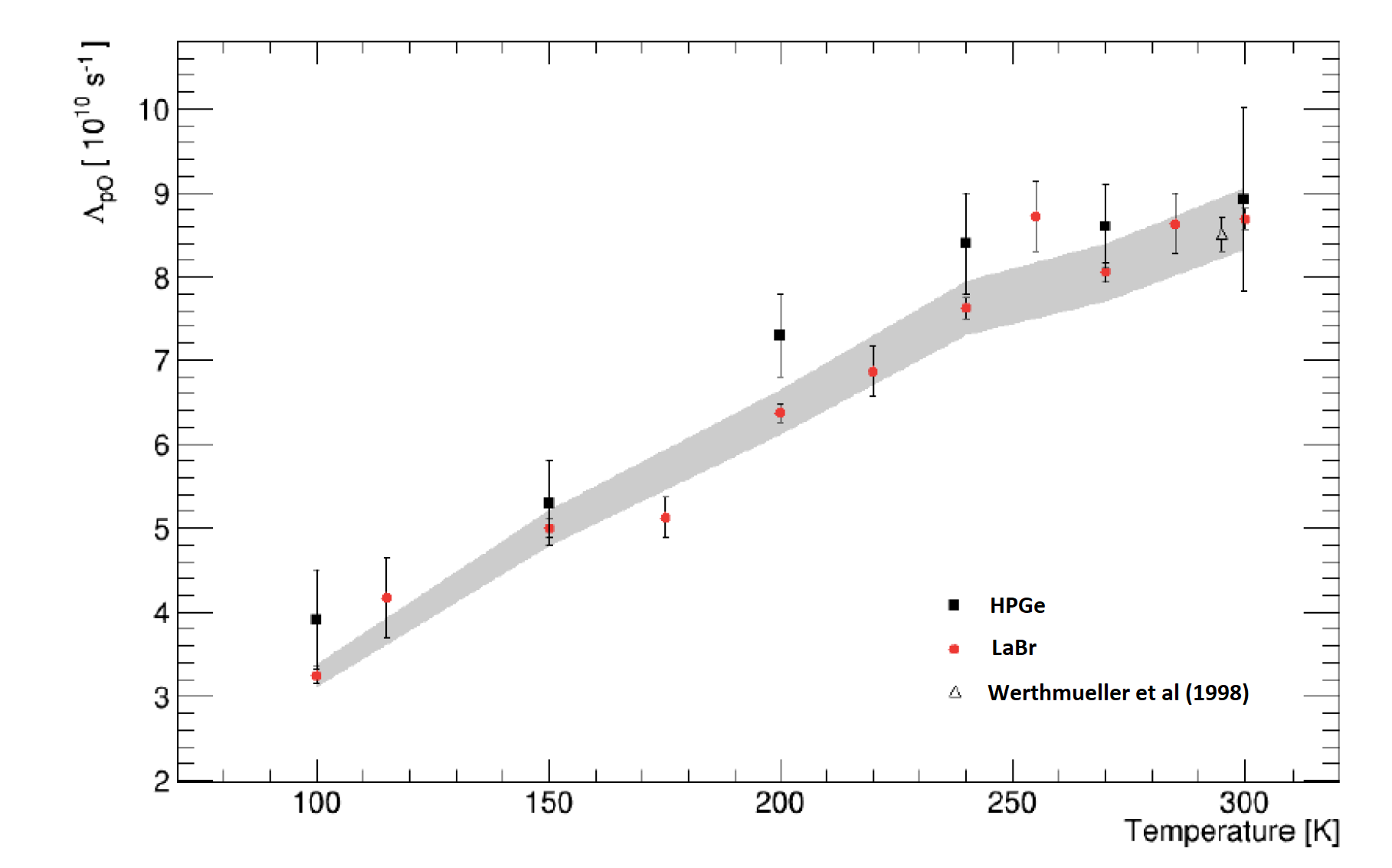
The efficiency of the method proposed by the FAMU collaboration relies on the muon transfer rate dependence on the muonic hydrogen energy and on the epi-thermality of the muonic hydrogen at the moment of the muon transfer. In our investigation of the temperature dependence of the muon-transfer process from the thermalized p atoms to oxygen, a strong monotonic rise of the transfer rate to oxygen in the temperature interval 103300 K has been observed [15], confirming previous experimental results at PSI [16]. Results on temperature dependence of the muon transfer rate to oxygen, as measured with LaBr3:Ce and HpGe detectors are shown in figure 4. Their theoretical interpretation is reported in reference [15], where a full discussion of systematics is also reported. Such a strong change enables to employ the muon transfer rate to oxygen as a signature of the kinetic-energy gain of the p atom.
4 The final experiment layout and expected performances
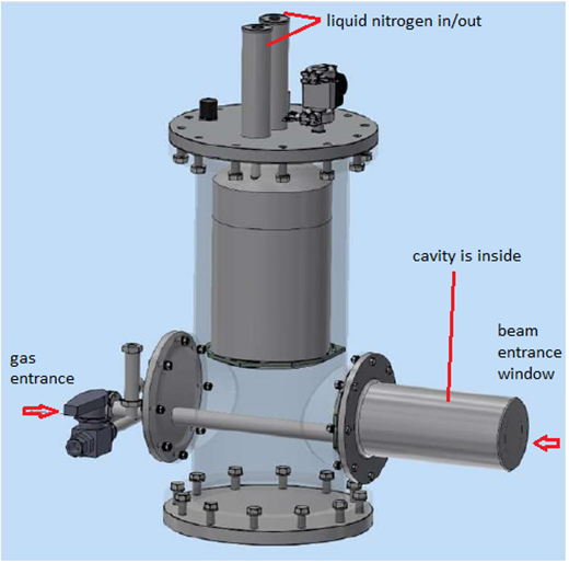
As the probability to stimulate an HFS transition is proportional to , with W laser pulse energy and T target temperature, the temperature should be the lowest possible to maximize the transition probability. At the same time, since a gas mixture of hydrogen and oxygen is used, the condensation temperature of oxygen limits the lowest possible temperature to about 60 K.
In addition, to increase the interaction path between the p atoms and the photons of the laser pulse an efficient multipass cavity is needed on the lines of what previously realized [17]. The optical cavity design is under study and presently encompass a cm3 illuminated volume in the target , transverse to the impinging muon beam [18]. The optical path leading the laser light towards the internal optical cavity will be sensitive to vibrations. Therefore, the target cooling is based on a passive liquid nitrogen system to optimize mechanical stability and eliminate the vibrations produced by the cryogenic pumps. Figure 5 shows the actual target design, which has led to the choice of a liquid nitrogen (LN2) 5 liters reservoir, that will allow a duty cycle of about 5 days at the operating temperature of 80 K.
The pulsed, tunable FAMU laser at 6785 nm has target parameters of an energy output of more than 1 mJ, with a line width less than 0.07 nm 333pulse duration 10 ns at a 25 Hz repetition rate.
The chosen scheme is based on direct frequency generation (DFG) in LiInS2 crystals with pump and signal coming from one narrowband fixed wavelength Nd:Yag laser (1064 nm) and a tunable narrowband Cr:forsterite laser (1262 nm) pumped by another Nd:Yag laser, synchronized to the first one. For the generation of an energy greater than 1 mJ at m the Nd:Yag laser must have an energy around 100 mJ and the Cr:forsterite of 35 mJ. For details on the layout of the laser system see reference [19]. The laser wavelength ( nm) will be measured precisely ( ppm) with solid state Fizeau interferometers and a cell filled with .
From a detailed Montecarlo simulation the signal to background ratio may be estimated, optimizing the data taking conditions. For what concerns the target the optimal conditions require a temperature of 80 K, at a pressure of 7 bar for a oxygen mixture. With the final laser energy of mJ we expect a signal to background ratio around 10 in the selected time window. Background will be evaluated taking alternatively one beam spill with laser on and one with laser off.
5 Conclusions
The method proposed by the FAMU collaboration to measure the Zemach proton radius has been demonstrated feasible via our measurement of the transfer function to oxygen. The full experimental setup is under realization, including the optical cavity, the target and the DFG MIR laser. A first spectroscopic run is foreseen for the beginning of 2020, before the long ISIS 2021 shutdown.
References
- [1] A. Antognini et al., Science 339, 417-420 (2013).
- [2] D. Bakalov, E. Milotti, C. Rizzo, A. Vacchi and E. Zavattini, Phys. Lett. A172, 277-280 (1993).
- [3] A. Adamczak, D. Bakalov, L. Stoychev, and A. Vacchi, Nucl. Instr. Meth. B281, 72-76 (2012).
- [4] A. Adamczak et al., J. Instrum. 11, P05007 (2016).
- [5] A.Adamczack et al., JINST 13 (2018) no 12, P12033
- [6] T. Matsuzaki et al., Nucl. Instrum. Meth. A465 365-383 (2001).
- [7] R. Carbone et al., JINST 10 (2015) no. 03,C03007
- [8] M. Bonesini, et al., JINST 12 (2007) C03035
- [9] M. Bonesini et al., Nucl. Instr.Meth. A936 (2019) 592; DOI: 10.1016/j.nima.2018.08.092
- [10] M.Bonesini et al., Pos EPS-HEP2015 (2015) 244
- [11] G. Baldazzi et al., JINST 12, C03067 (2017).
- [12] M. Soldani et al.,Nucl. Instr. Meth. A936 327-328(2019); DOI: 10.1016/j.nima.2018.11.003
- [13] M. Bonesini et al., PoS EPS-HEP2017 (2017) 777
- [14] R. Benocci et al., Nucl. Instr.Meth. A936 570-571(2019); DOI: 10.1016/j.nima.2018.10.030
- [15] E. Mocchiutti et al., submitted to Phys. Rev. A, ArXiv NuclEx/1905.02049
- [16] A. Werthmuller et al., Hyperfine Interact. 116, 1-16 (1998).
- [17] J. Vogelsang et al., Opt. Express 22, 13050-13062 (2014).
- [18] D.Bakalov, M.Stoilov, EPJ Web of Conference 181,01033 (2018).
- [19] L.I. Stoychev et al. in 9135, 91350J (International Society for Optics and Photonics, 2014).