- 3GPP
- 3rd Generation Partnership Program
- 5G
- Fifth Generation
- Adam
- Adaptive Moment Optimisation
- ANR
- Automatic Neighbour Relation
- AP
- Access Point
- ATC
- Air Traffic Control
- BS
- Base Station
- BPP
- Binomial Point Process
- C&C
- Command & Control
- CDF
- cumulative distribution function
- CDMA
- Code Division Multiple Access
- CD&R
- Conflict Detection & Resolution
- CFO
- Carrier Frequency Offset
- ComReg
- Commission for Communications Regulation
- CHO
- Conditional Handover
- DQN
- Deep Q-Network
- DDQN
- Dueling Deep Q-Network
- CSI
- Channel State Information
- EASA
- European Aviation Safety Agency
- FAA
- Federal Aviation Administration
- FSO
- Free-Space Optical
- GEO
- Geosynchronous Equatorial Orbit
- GPS
- Global Positioning System
- GS
- Ground Station
- HAP
- High Altitude Platform
- IoT
- Internet of Things
- IPNN
- Interference Prediction Neural Network
- KPI
- Key Performance Indicator
- LAP
- Low Altitude Platform
- LEO
- Low Earth Orbit
- LoS
- Line-of-Sight
- LTE
- Long Term Evolution
- LSTM
- Long Short-term Memory
- MAC
- Media Access Control
- MCP
- Matern Cluster Process
- MC
- Monte Carlo
- 3GPP
- 3rd generation partnership project
- MIMO
- Multiple Input Multiple Output
- MIP
- Mixed-Integer Programming
- MM
- Mapping Mechanism
- ML
- machine learning
- MNO
- Mobile Network Operator
- MILP
- Mixed-Integer Linear Programming
- NLoS
- non-Line-of-Sight
- NN
- Neural Network
- NRT
- Neighbour Relation Table
- OFDMA
- Orthogonal Frequency Division Multiple Access
- OOT
- Out-of-Tree
- OSI
- Open Systems Interconnection
- OTDoA
- Observed Time Difference of Arrival
- OTT
- Over-The-Top
- PV
- photo-voltaic
- probability density function
- PPP
- Poisson Point Process
- QoS
- Quality of Service
- RC
- Remote Control
- RL
- Reinforcement Learning
- REQIBA
- REgression and deep Q-learning for Intelligent UAV cellular user to Base station Association
- RSS
- Received Signal Strength
- SE
- Spectral Efficiency
- SIR
- Signal-to-Interference Ratio
- SINR
- Signal-to-Interference-and-Noise Ratio
- SNR
- Signal-to-Noise Ratio
- UAV
- Unmanned Aerial Vehicle
- UE
- User Equipment
- ULA
- Uniform Linear Array
- WSN
- Wireless Sensor Network
- WSN
- Wireless Sensor Network
- RV
- random variable
- PPP
- Poisson point process
- PGFL
- point generation functional
- probability density function
REQIBA: Regression and Deep Q-Learning for Intelligent UAV Cellular User to Base Station Association ††thanks: Copyright (c) 2015 IEEE. Personal use of this material is permitted. However, permission to use this material for any other purposes must be obtained from the IEEE by sending a request to pubs-permissions@ieee.org.
Abstract
Unmanned Aerial Vehicles are emerging as important users of next-generation cellular networks. By operating in the sky, UAV users experience very different radio conditions than terrestrial users, due to factors such as strong Line-of-Sight (LoS) channels (and interference) and Base Station (BS) antenna misalignment. As a consequence, the UAVs may experience significant degradation to their received quality of service, particularly when they are moving and are subject to frequent handovers. The solution is to allow the UAV to be aware of its surrounding environment, and intelligently connect into the cellular network taking advantage of this awareness. In this paper we present REgression and deep Q-learning for Intelligent UAV cellular user to Base station Association (REQIBA), a solution that allows a UAV flying over an urban area to intelligently connect to underlying BSs, using information about the received signal powers, the BS locations, and the surrounding building topology. We demonstrate how REQIBA can as much as double the total UAV throughput, when compared to heuristic association schemes similar to those commonly used by terrestrial users. We also evaluate how environmental factors such as UAV height, building density, and throughput loss due to handovers impact the performance of our solution.
Index Terms:
Cellular-connected UAVs, Machine Learning, Reinforcement Learning.I Introduction
UAVs are aircraft that operate without a pilot on board. Instead, they are either piloted remotely by a human operator, or they are controlled by computer algorithms. These devices are becoming increasingly used in a variety of applications, such as medical deliveries [1], building inspections, and surveillance [2]. The Covid-19 pandemic in particular has accelerated the worldwide adoption of UAVs for a variety of important use-cases, from disinfecting areas [3] to enforcing social distancing in crowds [4]. Outside of those emergency use-cases, businesses are beginning to use UAVs to deliver everyday items such as groceries [5], as well as for infrastructure inspections [6]. To enable these applications, the UAVs will require a reliable wireless data link with their pilot or other controlling entities. While current commercially-available UAVs rely on visual LoS connections to their pilot, there is growing interest in connecting the UAVs via cellular networks [7, 8, 9]. The emerging Fifth Generation (5G) family of cellular standards is intended to accommodate new types of users which require very high levels of reliability; this makes the 5G network an attractive option for facilitating UAV connectivity [10].
Until very recently, the cellular network was exclusively used by devices operating at – or close to – ground level. Existing cellular networks were designed with these users in mind, with BS locations chosen to create coverage ”cells” for the ground users, and the antennas configured to transmit signals towards the ground. Because they operate in the sky, UAVs experience very different radio conditions to those of ground users, and the design of existing cellular networks introduces significant issues for them [7]. Experimental trials have shown that while flying, UAVs are likely to receive sidelobe signals from the BSs, as the mainlobes are aimed towards the ground [11]. The sidelobe signal gain may be such that a UAV may receive a stronger signal from a BS which is kilometers away from it than from a BS which is closer. Furthermore, a UAV is able to establish unobstructed LoS channels to a large number of BSs. The consequence of this is that, while at ground level the network may be partitioned into coverage ”cells”, at greater heights the network coverage is highly volatile, with very strong interference from distant BSs and a large number of BSs that a UAV can connect to at any given moment [12]. In our prior experimental work [13], we demonstrated that a UAV flying in a city can successfully connect via strong side-lobe signals to small cells up to a kilometer away.
As it travels through an area, a UAV is likely to see very rapid signal fluctuations, and may potentially hand off from one BS to another very frequently. These frequent handovers may introduce significant overheads into the network performance, and degrade the service quality for the UAV link. In our prior work [14] we discussed some of the solutions that could be implemented by network operators to mitigate these handover issues, such as adjusting the Automatic Neighbour Relation (ANR) mechanisms used by neighbouring BSs to take into account the unique flight behaviours of UAVs. In addition to changes made on the side of the network by the operators, the UAVs themselves can be designed to tackle some of these connectivity issues. The 3rd generation partnership project (3GPP) has suggested that steerable, directional antennas should be used by the UAVs, as they can allow a UAV to improve its wireless link quality by reducing the power of undesirable BS signals (i.e. interference) [7]. A number of works have suggested that UAVs should optimise their flight trajectories with respect to the underlying cellular network, to improve performance. A variety of algorithms have been proposed for this trajectory optimisation, as discussed in the next section. While this type of optimisation is useful for scenarios where the UAV trajectory can be optimised with respect to cellular service, there are a variety of scenarios where the trajectory of the UAV may not be modified, either because the flight path is explicitly defined by the UAV mission (such as photography work) or because the UAV is being piloted in real-time by a human operator rather than a computer algorithm. Furthermore, algorithm-driven UAV swarm flights are currently heavily restricted under European Union (EU) regulations, and it is not clear when these restrictions will be lifted [15]. As such, we expect that human-piloted UAVs will make up a large part of the UAV landscape in the near future.
For these reasons, there is a need to explore intelligent UAV cellular connectivity that does not rely on optimising UAV trajectories. In these scenarios, the UAV can improve its service quality and manage its handover rate by intelligently choosing which BSs to associate with, using knowledge of its surrounding environment. When equipped with a steerable directional antenna, this would allow the UAV to align its antenna to create the best wireless channel for the given circumstances. This association decision will be complicated by the volatile radio environment discussed above, with factors such as the UAV mobility, the large number of candidate BSs with strong side-lobe signals, and the impact of LoS-blocking buildings all affecting the decision of which BS to connect to, and when to carry out a handover.
In our prior work [16] we addressed the issue of intelligent UAV-BS association in a static scenario where the UAV was hovering in place and needed to make a single association decision for its location. While our proposed neural network solution was shown to outperform conventional association schemes in terms of channel quality, as the scenario was static we did not address the issue of UAV movement and the resulting handovers. In this paper we extend our prior work by considering a scenario where a UAV needs to intelligently maintain a connection to the underlying cellular network while moving, by making multiple association decisions during flight. Our contributions are as follows:
-
•
We propose a novel neural network-based solution which we refer to as REQIBA, which allows a UAV equipped with a directional antenna to intelligently associate with nearby BSs during flight. This solution consists of a regression neural network and a Dueling Deep Q-Network (DDQN) module. The solution takes in state information about the environment, information about received signal power, interference, and current BS connection. The network then chooses a BS to connect to based on these factors, to maximise the data throughput.
-
•
We evaluate the performance of our REQIBA solution and demonstrate that addressing this problem in a mobility scenario is indeed a lot more complex than treating it as a series of static connection decisions. We show how REQIBA outperforms our prior solution in [16] by simultaneously increasing the total throughput and reducing the rate of UAV handovers.
-
•
We compare the performance of REQIBA against heuristic association schemes such as those found in the literature. We demonstrate how it outperforms these heuristic schemes under different environmental conditions, while exploring how these environmental conditions affect its performance improvement.
This paper is structured as follows. In Section II we review the related works. In Section III we outline our system model. In Section IV we introduce and describe our REQIBA solution. In Section V we describe how REQIBA is trained and evaluated. In Section VI we compare the performance of REQIBA against our prior solution in [16]. In Section VII we evaluate how REQIBA performs against the heuristic algorithms under various environmental conditions. Finally, in Section VIII we provide our conclusions and discuss directions for further investigation.
II Related Works
The cellular connectivity issues experienced by flying UAVs have been extensively explored. In [17] Qualcomm reports the results of a series of simulations and field measurements which determine that UAVs are exposed to stronger interference than ground users. In [18] the authors apply stochastic geometry to demonstrate how UAVs experience throughput degradation with increasing heights, due to growing interference power. In [19, 20] the authors use simulations to show how UAVs experience very high handover failure rates due to strong interference conditions at large heights. In [21], authors perform an experimental flight with a UAV at different heights and speeds, and conclude that a UAV performs approximately 5 times more handovers than ground users moving at the same speed. In our prior work [22] we apply stochastic geometry to analytically characterise the coverage probability and throughput of a UAV that is connected to a network of terrestrial BSs via directional antenna. In our prior work [23] we demonstrate how BS sidelobes can cause frequent UAV handovers during UAV vertical movement.
As UAVs are highly mobile devices, the wireless community typically approaches the problem of UAV cellular connectivity from the perspective of optimising the UAV trajectory. In [24] the authors consider a UAV that needs to fly between two locations, in a manner that minimises the flight time while maintaining a reliable cellular link. They use a graph representation of the network and apply Dijkstra’s algorithm to find the route of the UAV. The authors of [25] optimise the movement of a UAV around a map of LoS-blocking buildings, to ensure the UAV maintains a LoS channel to its BS. A similar work is carried out in [26], where UAV relays are intelligently positioned around known user locations as well as the locations of buildings. In [27] the authors optimise the UAV trajectory given available landing sites where the UAV can land and reduce its energy consumption. As there is significant research interest in the UAV trajectory optimisation topic, machine learning (ML) is seeing widespread application in the UAV domain. In our prior work [28] we develop a multi-agent ML scenario where multiple UAV BSs are deployed to provide service in a disaster scenario. Using distributed multi-agent Q-Learning the UAVs optimise their placement above the user locations while simultaneously reducing their energy consumption. In [29] the authors consider a Deep Q-Network (DQN) algorithm to optimise the trajectory of multiple UAVs in a way that ensures that they have a sufficient connection to a terrestrial BS with massive MIMO antennas. The authors of [30] consider a mobile edge computing scenario where a DQN is applied to optimise a UAV’s trajectory and allow it to maximise the amount of computing tasks it offloads from ground users. In [31] the authors consider an Internet of Things (IoT) scenario where a UAV relay applies a DQN to adjust its trajectory around IoT devices, while wirelessly recharging its battery at certain locations. In [32], authors investigate interference-aware trajectory optimisation using game-theory and ML for the purpose of maximizing energy efficiency and minimizing wireless latency and the UAV interference on the ground network. Authors in [33] propose an ML approach to find an optimal trajectory which minimizes the travel time while maintaining connectivity with the cellular network. Meanwhile, the work in [34] proposes a deep learning-based framework to manage the dynamic movement of multiple UAVs in response to ground user mobility so as to maximize the sum data rate of the ground users. It should be noted that the works described above assume interference-free channel conditions, omni-directional antenna radiation patterns of the UAVs and BSs, guaranteed LoS propagation conditions, or some combination thereof. This allows for tractable optimisation problems and simplifies the UAV-BS association behaviour, but it may not reflect a realistic urban environment or UAV use-case.
Along with the ongoing work on UAV trajectory optimisation, the wireless community is also beginning to address the issues associated with UAV handovers using ML tools. For instance, the authors in [35] show how ML can be used to dynamically adjust the BS antenna tilt angles. The authors apply model-free Reinforcement Learning (RL) to the BS antenna tilt such that the agent balances the received signal power for a UAV user passing overhead with the throughput of the ground users. The authors demonstrate how this intelligent antenna tilting can help reduce the UAV handover rate without significant performance loss for the ground users. In [36], the authors consider a joint BS selection and resource allocation problem for moving UAVs. The authors apply reinforcement learning to simultaneously select the serving BS and the allocated resource blocks with the aim of minimizing the uplink interference created by the UAV for the ground users, while keeping the rate of UAV handovers manageable. A similar problem is addressed in [37], where the authors intelligently select BS associations for a UAV moving along a known trajectory to minimise the rate of handovers. In [38], the authors envision a method for managing a UAV flight path to coordinate enhanced handover in 3GPP networks. In [39] the authors propose using ML to estimate channel conditions in noisy environments, as well as the use of Long Short-term Memory (LSTM) networks to predict UAV trajectories in future timesteps for handover planning. In our prior work [16], we consider the problem of UAV association, where the UAV is equipped with a directional antenna for communication, and an omni-directional antenna for sensing. Our proposed ML solution in that paper uses the available channel information from the omni-directional antenna as well as the known locations of the interfering BSs to infer which BS will exhibit the best channel conditions for the directional antenna.
This paper extends our prior work in [16]. While our prior work considers optimising the channel quality in a scenario where a UAV is hovering at a fixed location, in this work we consider a moving UAV. This movement introduces the issue of UAV handovers, which complicates the association problem and requires an entirely new ML solution. Note that our work differs from existing works such as [36] and [37] in that we consider a throughput-maximisation problem for a UAV which communicates via a steerable directional antenna rather than an omni-directional one. This complicates the process of gathering environmental information for the association decision, which requires us to use a more complex ML solution to successfully optimise the UAV performance, as we will demonstrate in later sections. We further differentiate our work from the state-of-the-art by considering the effect of BS antenna side-lobes, LoS blockage due to buildings, as well as inter-cell interference from neighbouring BSs, all of which result in a more complicated radio environment.
III System Model
We consider a scenario where a UAV is performing a mission in an urban environment, such as a package delivery. The UAV is being piloted remotely, either by a human operator or by a flight controller, with the wireless data connection being carried out via the underlying cellular network. We assume that the UAV flight trajectory is not planned with respect to the locations of the underlying cellular network infrastructure, either because the pilot entity is not aware of the infrastructure locations and performance, or because the UAV mission takes precedence when planning the UAV trajectory. The underlying cellular network consists of BSs which are horizontally distributed as a homogeneous Poisson point process (PPP) of intensity , at a height above ground. Elements represent the projections of the BS locations onto the plane. The UAV travels from an initial location to a final location in a straight line over a length of time T. We discretise time into timesteps: this lets us partition the travel vector of the UAV into coordinates at different timesteps in the journey. We define the vector of these UAV coordinates as , where denotes the coordinates of the UAV in the -th timestep. The UAV height above ground is assumed to remain constant throughout the flight due to factors such as UAV mission requirements or air traffic control guidelines. The UAV height is denoted as . For an exploration of intelligent cellular-UAV height adjustment the reader is referred to our prior work [40]. Let denote the horizontal distance between the coordinates and , and let denote the vertical angle, where .
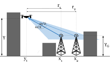
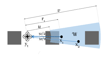
The UAV is equipped with two sets of antennas: an omni-directional antenna for BS pilot signal detection and signal strength measurement, as well as a directional antenna for communicating with the UAV’s associated BS. The omni-directional antenna has an omni-directional radiation pattern with an antenna gain of 1, while the directional antenna has a horizontal and vertical beamwidth and a rectangular radiation pattern; using the antenna radiation model in [41], the antenna gain is given as inside of the main lobe and outside. We denote the coordinates of the BS which the UAV is associated with at time as and its horizontal distance to the UAV as . Whenever the UAV connects to a BS it aligns its directional antenna towards ; this results in the formation of an antenna radiation pattern around which we denote as , as depicted in Fig. 1. This area takes the shape of a ring sector of arc angle equal to and major and minor radii and , respectively, where
| (1) |
with denoting absolute value. The BSs which fall inside the area are denoted by the set . The BSs in the are capable of causing interference to the UAV-BS communication link, as their signals may be received by the UAV’s directional antenna with non-zero gain.
As we are considering an urban environment, buildings will affect the wireless signals by blocking LoS links. We model these buildings as being distributed in a square grid, following the model proposed by the ITU in [42]. The density of buildings per square kilometer is and the fraction of the ground area covered by buildings is . All buildings have the same horizontal dimensions, and each building has a height which is a Rayleigh-distributed random variable with scale parameter . The UAV will have an unobstructed LoS channel towards a BS at time if there exist no buildings which intersect the straight line between at height and at height . Otherwise if there is at least one building that intersects this line then the channel is non-Line-of-Sight (NLoS).
We assume that the BSs have tri-sector antennas, with each antenna being a Uniform Linear Array (ULA) with antenna elements. For tractability we model these antennas as being horizontally omni-directional with horizontal gain 1. The vertical gain of these antennas is a function of the angle between the UAV and the BS and is defined similar to [43] as
| (2) |
When the UAV is connected to the BS at at timestep , the Signal-to-Interference-and-Noise Ratio (SINR) of the signal received by the directional antenna is given as
| (3) |
where is the BS transmit power, is the pathloss exponent, is an indicator variable which denotes whether the UAV has LoS or NLoS to its serving BS at timestep , is the near-field pathloss, is the noise power, and is the aggregate interference power received from the BSs in the set . As we are considering discrete timesteps with durations in the order of seconds, we approximate the channels as having no fast-fading effects, since effects such as multipath fading are expected to average out over the given timescales [18, 25]. However, the instantaneous SINR experienced by the UAV at a given moment may be affected by a number of factors, including multipath fading. If this multipath fading follows a Nakagami-m distribution the cumulative distribution function (CDF) of the instantaneous SINR can be derived mathematically. These derivations are given in the Appendix.
The throughput per unit of bandwidth at timestep is given by the Shannon bound as
| (4) |
As already mentioned, we assume that the UAV points its directional antenna at the BS it is currently associated with. The UAV is capable of seamlessly tracking the changing BS orientation using its directional antenna as it moves. If, however, the UAV changes its associated BS in a timestep then the UAV will spend a portion of that timestep realigning its directional antenna towards the new BS. We assume this antenna realignment, along with the handover signalling involved [18], causes an overhead which reduces the effective throughput in that timestep. A number of factors will determine the extent of this overhead, such as the configuration of the network by the network operators, the handover protocols in place, and the design of the UAV itself. For example, the ANR mechanism in the BS network may not be configured to support UAV users attempting handovers to distant BSs, in which case the handover process will be delayed with additional signalling [14]. The network may adopt new, streamlined handover mechanisms to support 5G vehicular users [44, Section VIII.B], which will also result in more streamlined handover signalling for the UAV user. Finally, handover delays may occur if the UAV directional antenna relies on alignment via the physical rotation of the UAV frame, which can take up to several seconds for a quadcopter style UAV [45]. To preserve the generality of our work, all of these factors are abstracted into the handover penalty , where smaller values of correspond to bigger performance impact; the exploration of the relationship between the aforementioned factors and the resulting performance overheads is left for a future work.
IV REQIBA
IV-A Problem Statement
Similar to the state-of-the-art, which considers UAV optimisation via decentralised algorithms, we assume that the UAV runs an algorithm on-board its hardware that allows it to make intelligent decisions based on observed information. The UAV is to fly through the environment from a starting point to an ending point over timesteps. At every timestep it is to make a decision about which BS it should be connected to for that timestep. If it decides to connect to a BS other than the one it is currently connected to, it will carry out a handover in that timestep. The reward function for the timestep is given as
| (5) |
where is the handover penalty factor. It follows that the smaller the value of the less desirable it is for a handover to occur.
The optimisation problem is stated as follows:
| (6a) | |||
| (6b) | |||
where denotes the cardinality of the set and denotes the indicator function, which equals when the expression within the parentheses is true. The constraint in Eq. (6b) guarantees that the UAV must be connected to exactly one BS in at each timeslot in the episode.
In theory the UAV may choose from any BS in for the optimisation problem above, but from a practical perspective the choice tends to be limited to only a subset of those BSs. From our prior work [16] we have observed that the UAV is likely to get the best connection from one of the closest BSs to it, or one of the BSs with the strongest received signal power. We therefore denote a subset of BSs , where consists of the closest BSs to the UAV at timestep , as well as the BSs with the strongest received signal power at the UAV at that timestep (as measured by the omni-directional antenna). Therefore, at timestep the action the UAV takes is to choose from one of the candidate BSs in . Note that the -th closest BS at timestep may also be the -th strongest signal BS where , which means that the cardinality of set may be lower than . The omni-directional antenna on the UAV also allows it to select candidate BSs based on the highest omni-directional SINR; however, since the received interference at the omni-directional antenna will greatly differ from the interference received by the directional antenna once aligned, the omni-directional SINR of the candidate BSs is unlikely to be indicative of the directional antenna SINR (this will be demonstrated in Section VII). For this reason, we do not consider the omni-directional SINR of the candidate BSs for the subset .
IV-B Environment Information
Before describing our proposed REQIBA solution we specify what state information is assumed to be available to the UAV for use in its decision-making:
- •
- •
-
•
The 3D coordinates of the UAV and the BSs in . The UAV knows its location from its Global Positioning System (GPS) coordinates, while the locations of the BSs are provided to it by the network. This location information is independent of the received signal power measurements carried out by the omni-directional antenna; as such, the UAV knows the locations of BSs even if they are too far away to have their pilot signals decoded by the antenna. This information is assumed to be error-free, and in the case of the moving UAV is updated in real-time.
-
•
The 3D topology of the environment, as in [26]. To safely navigate through the urban environment we assume the UAV has information on the locations and heights of buildings around it. This topology information is error-free, and assumed to be accurate enough to allow the UAV to determine whether it has an unobstructed LoS channel to a given BS using a ray trace.
-
•
The directional and omni-directional antenna parameters. The UAV is aware of the gain patterns for both sets of its antennas, and is able to determine the area that would be illuminated by the directional antenna should it point it towards a given location.
-
•
Whether or not it will need to optimise its cellular link in the next timestep. We assume the UAV knows when it no longer needs to continue optimising its cellular connectivity (i.e., the end of the optimisation episode). This information is necessary to tell the learning algorithm whether it should consider future timesteps when choosing an action, or only the current timestep.
IV-C REQIBA Solution Structure
It is clear from the reward function in Eq. (5) and the SINR expression in Eq. (3) that the throughput at timestep , which is obtained after the UAV chooses the BS for that timestep, is affected by four factors: whether a handover occurs, the performance penalty for the handover, the received signal power from the associated BS, and the interference power from the other BSs. The handover penalty and the interference powers are not known explicitly by the UAV, and thus cannot be used directly in the decision-making process. Recall that the omni-directional antenna that the UAV uses for sensing and the directional antenna used for communication have different radiation patterns, and that the UAV aligns its directional antenna towards its chosen BS, with the interfering BSs coming from the area . The UAV omni-directional antenna is not able to measure the interference power that comes specifically from the area : this needs to be estimated in some other way. The UAV has access to the map of the BSs, and knows its own directional antenna beamwidth, so it can determine which BSs will fall inside the area and cause interference.
The inputs to our REQIBA solution are as follows. The received signal powers of the candidate BSs are provided as a vector , where . The handover information is conveyed with a vector of binary flags where if and 0 otherwise, to indicate which of the candidate BSs the UAV is currently associated with. Information about the interfering BSs consists of two input matrices and , where denotes the number of interfering BSs to consider per link. contains the horizontal distances of the interfering BSs to the UAV, where the -th row corresponds to the area illuminated when the UAV points its directional antenna towards the -th candidate BS, and the -th column represents the -th closest interfering BS in the corresponding illuminated area. The matrix contains binary flags to indicate whether the corresponding interfering BSs have LoS or NLoS to the UAV, as determined from the building topology map [26]. If the -th candidate BS has fewer than interferers then the remaining entries in the -th rows of and take null values. The final two inputs are the UAV height above ground and a binary flag which takes a value of 1 if the current timestep is the final timestep in the episode.
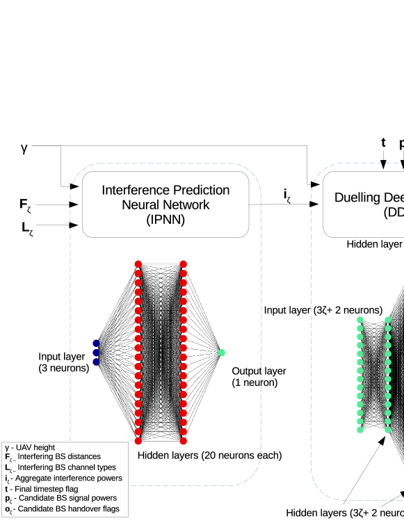
From Fig. 2 it is clear that the REQIBA solution consists of two separate modules, which are detailed below.
IV-C1 Interference Prediction Neural Network
Known information about the interference consists of the horizontal distances of the interfering BSs to the UAV and their channel types. To estimate the aggregate interference power using this information, we propose a regression neural network circuit which we refer to as the Interference Prediction Neural Network (IPNN), shown on the left-hand side of Fig. 2. This IPNN is trained to estimate the received power from a BS given a known horizontal distance to the UAV, the UAV height above ground, and whether or not there is an LoS obstruction between the two (from the building topology map available to the UAV). Providing this trained neural network with the BS distances and channel types in the known area will allow REQIBA to estimate the total received interference power when the antenna is aligned with the given candidate BS, which it can then pass on to the DDQN for candidate BS selection.
This IPNN circuit consists of an input layer, two dense layers, and an output layer. The dense layers have 20 neurons each, with linear and tanh regularisation functions. The input consists of the matrices and and UAV height . The output consists of a matrix of estimated signal power values for each of the corresponding interfering BSs. We sum the rows of this matrix to give the final output vector , where is the estimated total interference power in the area that would be experienced by the UAV if it chooses the -th candidate BS at timestep .
IV-C2 Dueling Deep Q Network
Having estimated the interference power for each of the candidate BSs, and knowing their received signal powers and the current UAV association already, we propose a DDQN module to make the decision about which candidate BS to associate with for the current timestep. The DDQN module is based on model-free RL. In RL, the UAV chooses an action based on the observed environmental state at each timestep, based on what it expects will maximise the long-term reward. In a classic RL problem a so-called Q-Table is used, which specifies the value of each possible action for a given environment state. As the UAV takes actions, the RL algorithm will observe the resulting action rewards and update the Q-Table accordingly. The Q-Table approach has been shown to be very effective for simple environments and action spaces, but if the environment is very complex then the Q-Table becomes very large and difficult to train. The solution to this is to apply a neural network to approximate the function of the Q-Table, that is, return the estimated Q-values of all possible actions for a given state. We apply a DDQN architecture to perform the function of this Q-Table, as shown on the right-hand side of Fig. 2.
The DDQN takes the inputs , , and from the system input and from the IPNN. The Q-value of a state-action pair is the sum of the state value and the action advantage functions; a typical DQN estimates the Q-value directly, whereas a DDQN contains two parallel streams which estimate the state value and the action advantage functions separately, before combining them together to form the Q-value [46]. This architecture has been shown to improve the policy evaluation of the neural network compared to the basic DQN architecture. The DDQN consists of an input layer, followed by a dense layer, followed by a split into two streams. In each stream there are two dense layers. The outputs of the streams are then passed into a combination layer where they are joined together to give Q-values, one for each possible action (candidate BS) for the given state. The output of this DDQN is a vector of the Q-values, with the action that has the largest Q-value being selected for the given timestep. Note that we do not explicitly provide any information to the DDQN about the handover penalty ; the negative impact of handovers is to be learned by the DDQN over the course of its training, which will enable it to infer the cost of a handover in its decision process.
V Training & Evaluation Methodology
The environment described in Section III is simulated in the R programming language, using the ”Keras” library for the REQIBA solution [47]. The environmental parameters of the simulated environment are given in Table I, and the REQIBA hyperparameters are given in Table II. In Section VII, to test the robustness of our approach, we will test the performance of REQIBA for different environmental parameter ranges; these ranges are shown alongside the baseline values of Table I. The hyperparameter values shown in Table II were chosen by us based on prior experimental testing, which suggested their suitability for the REQIBA scenario.
| Parameter | Baseline Value | Test Range |
| Carrier Frequency | 2 GHz | - |
| Simulation Area | 5 km x 5 km | - |
| Building density | 300 | 100-1000 |
| Building land coverage | 0.5 | - |
| Building height scale param. | 20 m | - |
| UAV velocity | 10 m/s | - |
| LoS pathloss exponent | 2.1 | - |
| NLoS pathloss exponent | 4 | - |
| BS transmit power | 40 W | - |
| Near-field pathloss | -38.4 dB [48] | - |
| BS antenna elements | 8 | - |
| Noise power | W [48] | - |
| Handover penalty factor | 0.5 | 0-1 |
| BS height above ground | 30 m | - |
| BS density | 5 | 1-10 |
| UAV height | 100 m | 20-200 m |
| UAV antenna beamwidth | 45 deg. | 30-90 deg. |
| MC trials | 2000 | - |
| Episodes per MC trial | 1 | - |
| Timesteps per episode | 100 | - |
| Timestep duration | 1 second | - |
| Parameter | Value |
| Q-value discount factor | 0.1 |
| Initial epsilon value | 1 |
| Epsilon decay value | 0.995 |
| Minimum epsilon value | 0.001 |
| Replay memory size | 10000 entries |
| Replay batch size | 2048 |
| Candidate BS number | 10 |
| Interfering BS number | 125 |
Before we can evaluate our REQIBA solution it needs to be trained. As REQIBA consists of two separate modules it is trained in two stages, which we refer to as offline training and online training. The offline training involves training the IPNN. As this module is a regression neural network, it relies on supervised learning, wherein labelled data is presented to the network and it learns the relationship between the input and the output (the label). For our scenario this corresponds to the IPNN being presented with a dataset of interfering BS distances, channel types, UAV heights and the resulting received signal powers of those BSs. In a real-world scenario, this dataset would be generated by having the UAV fly around an urban environment and measure BS signal powers with its directional antenna, while also recording its horizontal distance and channel type. We simulate the generation of this dataset by simulating the urban environment over a number of Monte Carlo (MC) trials, with the UAV positioned at the centerpoint of the environment. In each trial the UAV points its directional antenna towards a random BS and records the signal power observed by the directional antenna, alongside the horizontal distance to the BS, its channel type (based on the known building topology) and the height of the UAV. These measurements populate a dataset which is then used to train the IPNN.
Having trained the IPNN, we carry out the online training of the DDQN, following the procedure shown in the Algorithm 1 pseudocode below. We refer to it as online training, as the DDQN is trained during the normal operation of the UAV, in the typical manner of RL. We again simulate a number of MC trials with generated urban environments and UAV travel trajectories. For each MC trial the UAV moves from the start to the end-point in a straight line over timesteps. We use a technique known as Double DQN to train the DDQN [49, Chapter 4]; this involves creating two DDQNs during the training process referred to as the ”Evaluation DDQN” and the ”Target DDQN”. The former is used to evaluate the action values and undergoes training, while the latter is used to select the best action for the next observed state. By separating these operations between the two DDQNs we allow the algorithm to converge faster during training. At each timestep REQIBA takes the state inputs, generates the aggregate interference powers via the IPNN, then estimates the Q-values via the Evaluation DDQN. We follow an -greedy training procedure, following which a candidate BS is chosen either at random with probability or based on the highest Q-value as estimated by the Evaluation DDQN with probability . The reward (timestep throughput ) is observed. The state inputs, the action taken, the reward, and the next state inputs are stored in a so-called replay buffer. Once this replay buffer has a sufficient number of entries it is used to train the Evaluation DDQN, via uniform sampling of the replay buffer into batches of training data. For each entry in the sampled batch, the algorithm calculates a Q-value for the given state-action pair based on the observed reward, chooses the best action for the next observed state using the Target DDQN, and then estimates the highest Q-value of the next state, discounted by a certain amount. These new Q-values are then used to train the Evaluation DDQN. The value of is decayed by a certain factor at the end of each step, so the training process will randomly explore the environment in the beginning and then rely less and less on random decisions as the DDQN becomes more and more trained. At the end of the training episode the Target DDQN is updated with the weights of the Evaluation DDQN. Once the replay buffer is full, old entries in it are overwritten with new entries.
We propose evaluating our REQIBA solution in two stages. In the first stage we compare the performance of REQIBA to the BS association solution in our prior work [16]. While this prior solution is designed for a static scenario, it can be applied to a mobile scenario as well. By taking this prior solution as a baseline we quantify the performance gains that REQIBA can provide. REQIBA is composed of the IPNN and DDQN modules which process parts of the state inputs, and both of these modules can be used to make a BS association decision in isolation of one another. To verify the performance benefits of the full REQIBA solution we compare it against the performance of the IPNN and DDQN modules in isolation.
In the second evaluation stage we verify the performance of REQIBA against heuristic BS association schemes. As the UAV has access to important information about the environment, it is capable of making BS association decisions by following simple heuristic schemes. In our prior work [16] we demonstrated that the performance improvement from applying ML is highly dependent on the environmental conditions, and that under certain circumstances the simple heuristic association schemes may be sufficient for the UAV. For this reason, we are interested in comparing how REQIBA performs against heuristics under various environmental conditions. This will give us valuable insight on how the environment can determine the most appropriate type of association policy.
VI Evaluation Results Against Prior Model
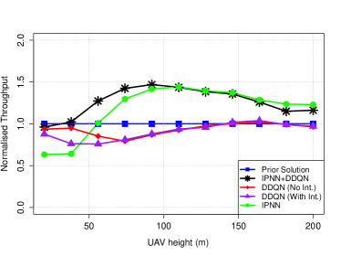
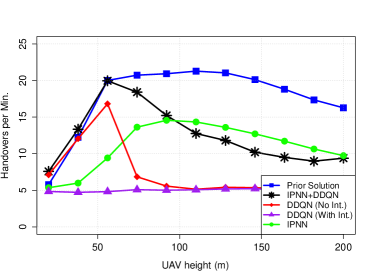
In this section we compare the performance of the two REQIBA modules, the IPNN and the DDQN, against the performance of our prior static model from [16]. The purpose of this comparison is two-fold. First, we verify that the REQIBA solution offers a performance improvement over our prior solution, which does not make use of the IPNN and DDQN modules. Second, as REQIBA makes use of two connected modules to make an association decision, we verify that both modules offer measurable performance benefits when working together, to validate our choice of solution. We consider two performance metrics for our comparison: the total throughput over an entire episode, and the handover rate over an episode. This performance comparison is carried out across a range of UAV heights. For ease of comparison of the episode throughput, we take the total episode throughput of our prior solution as a baseline, and normalise the total episode throughput of the IPNN and DDQN modules with respect to it. For this comparison we consider three variants of the DDQN module: The results labelled ”IPNN+DDQN” use the full REQIBA solution as described in Section IV; the results labelled ”DDQN (No Int.)” are for the DDQN module acting in isolation with no inputs relating to the interference power; and the results ”DDQN (With Int.)” are for the DDQN acting in isolation and taking in the matrices and directly. Finally, the results labelled ”IPNN” show the performance when an association decision is made by choosing the BS with the lowest interference power in as estimated by the IPNN, without involving the DDQN.
We report that the DDQN-based approaches appear to converge on a solution after approximately 500 MC trials. The plots below show the average performance for the remaining 1500 MC trials. Fig. 3 shows the resulting throughput, and Fig. 4 the handover rates. We note that REQIBA improves the episode throughput by as much as 50% when compared to the baseline, while offering a significant reduction in the handover rate. This is because REQIBA offers several improvements over the prior solution. First, the dedicated IPNN module is better at estimating the expected interference power than the prior solution, which makes REQIBA more reliable in its candidate BS selection. Second, REQIBA is able to explicitly learn the negative impact of handovers and take that into consideration by means of its DDQN module, whereas the prior solution is designed for a static UAV scenario, and so ignores the impact of handovers. This causes the prior solution to make an excessive number of handovers during UAV flight, which negatively impacts the episode throughput. This behaviour suggests that the mobile UAV connectivity problem cannot be adequately solved by treating it as a sequence of independent static decisions, as the prior solution does.
Comparing the performance of the two modules we see that it is heavily determined by the UAV height. The IPNN in isolation gives very similar throughput improvement as the joint IPNN+DDQN solution at greater heights, although it performs worse than the baseline at low heights. We explain these observations by the effect of interference at different heights. At low heights interference power is low and the association decision is primarily down to the received signal power from the BSs, which makes the IPNN block not add much value to the decision-making. This results in the IPNN+DDQN solution performing very similarly to the baseline. As the height increases, the interference starts to play more and more of a role, and so does the IPNN module. As a result, the solutions which use the IPNN module provide an improvement over the baseline. Note that the baseline solution is capable of inferring some information about interference (albeit not as well as the dedicated IPNN module) and so it ends up outperforming the DDQN module when the latter is not connected to the IPNN. It is interesting to note that passing information about the interfering BSs directly to the DDQN does not improve its performance when compared to not passing it that information; it appears that the DDQN is not capable of learning to directly interpret the interference power from the BS distances and channel types, and needs the IPNN module to perform this function. While the DDQN may not be able to provide a good episode throughput without the help of the IPNN, it still plays an important role in managing the rate of handovers, as we demonstrate in Fig. 4. We observe how the IPNN+DDQN solution is able to achieve a lower handover rate at greater heights than the pure IPNN solution, while still managing a very similar throughput. This demonstrates that while the IPNN module by itself may be sufficient for maximising the episode throughput when the UAV is operating in certain interference-heavy conditions, the DDQN module is needed to reduce the resulting rate of handovers. We explore this behaviour further in the next section.
The run-time of the REQIBA algorithm is tested on a Dell Latitude E5550 laptop, with an Intel i7-8665U CPU at 1.9GHz clock frequency, and 32GB of RAM. The online part of the IPNN+DDQN solution (both evaluation and training) takes approximately 420ms to run over a single time-step; given that the time-step is modelled as lasting one second we note that the algorithm can feasibly run in real-time on portable hardware.
VII Evaluation Results Against Heuristic Association
Having verified that our proposed REQIBA solution provides a significant performance boost over our prior solution, we now evaluate how well REQIBA compares against heuristic association schemes under different environmental conditions. As the problem of UAV association and handover is new, there is no established performance benchmark to compare against; we therefore perform a comparison against commonly adopted heuristic solutions. As we observed in the previous section, the IPNN module by itself can provide good performance under some circumstances, which is why we include it alongside the full IPNN+DDQN solution in the following results. The heuristic algorithms selected in this section are detailed below:
-
•
Closest BS association: As the UAV has a map of the BSs, it can determine which BS is the closest to it at any given timestep. Under this association scheme the UAV always connects to the closest BS, regardless of the received signal powers or current association. This association is depicted in blue in the figures below.
-
•
Highest SINR association. The omni-directional antenna on the UAV can measure the SINR of the channel for the strongest signal BSs around it. While this omni-directional SINR will differ from the SINR of the directional antenna when aligned, it can still be used to make an association decision directly, instead of using the REQIBA modules. This type of association corresponds to the usual association policy used by ground users. This association is depicted in red.
-
•
Shortest mean distance association. We have assumed in our scenario that the UAV does not know its trajectory and where it will be in future timesteps. For the sake of a heuristic comparison, we relax this assumption. If the UAV knows its trajectory over the whole episode, it can choose to connect to the BS which has the shortest average distance to the UAV across all timesteps. This association is depicted in orange.
-
•
Angle alignment association. If the UAV knows the locations of the BSs and it knows its own trajectory, it is aware of the BS whose direction is the closest to the direction that the UAV is travelling in. To represent a scenario where realigning the directional antenna may be undesirable, we consider an association scheme where the UAV associates with the BS which is the best-aligned with the direction of the UAV flight. This association is depicted in purple.
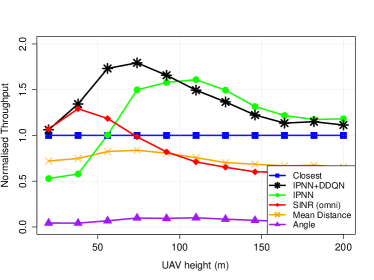
Unless stated otherwise the results in the figures below are based on the parameter values in Tables I and II. In the following subsections we vary the UAV height, BS density, building density, UAV antenna beamwidth, and handover penalty, and report on the comparative performance of REQIBA against the other association schemes. As in the previous section, we normalise the episode throughput of the different association schemes with respect to a baseline, which in this section corresponds to the episode throughput achieved from the closest association scheme. As before, the training appears to converge on a solution after approximately 500 MC trials, with the average performance over the remaining 1500 MC trials shown in the figures.
VII-A UAV Height
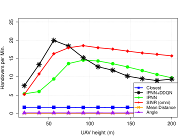
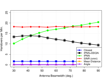
In Fig. 5 we show the normalised throughput achieved for the different association schemes under varying UAV heights. We note that the IPNN+DDQN association scheme outperforms all of the heuristics across the entire range of heights, giving as much as a 70% throughput improvement over the best heuristic scheme. As in Fig. 3, the IPNN association scheme gives poor performance at low heights where interference power is low, and gives good performance at large heights, slightly improving on the IPNN+DDQN scheme. At low heights the BS antenna sidelobe gain plays an important role in the signal performance. As a result, the IPNN+DDQN association scheme, which takes into account several factors such as interference, candidate BS signal strengths, and the cost of handovers, is able to outperform any other association scheme which only considers one factor, while the IPNN association scheme performs worse than the simple SINR heuristic, despite making use of a trained neural network. At large heights, however, the dominating factor is interference, and choosing a BS exclusively based on the resulting interference gives the best throughput.
When we consider handover in Fig. 6, we can see that the IPNN+DDQN gives the largest handover rates at the lower heights, before dropping to values below the SINR and IPNN association schemes. At low heights, the radio environment is highly volatile, with buildings frequently blocking the LoS channel and strong BS sidelobe gains being present. As a result, the IPNN+DDQN scheme frequently changes the associated BS. Because the SINR of the steerable directional antenna changes so rapidly, it has a higher handover rate than the SINR or the IPNN schemes which respond to changes in the omni-directional SINR and the interference powers, respectively. As the height increases, the UAV establishes uninterrupted LoS channels with more BSs more frequently, which combined with the weaker sidelobe antenna gains result in less channel fluctuations, and therefore less handovers. As the IPNN+DDQN learns to reduce unnecessary handovers, it results in a lower handover rate than the SINR or IPNN schemes. On the other hand, the fact that REQIBA-based association schemes are very dynamic in responding to the changing radio environment means that they still result in a much higher handover rate than the closest BS association scheme across the entire range of heights. Considering that at very large heights the REQIBA-based schemes offer a relatively modest throughput improvement (approximately 20%) over the closest BS association, this significant increase in handover rates may not be justified, in which case it may be worthwhile for the UAV to rely on simple closest BS association when operating at large heights.
It is also worth noting that the mean distance-based association and angle-aligned association give relatively poor throughput performance, despite benefiting from a priori knowledge of the UAV travel path, which the other association schemes are assumed not to know. The advantage of these association schemes is that they allow the UAV to pick a single BS to connect to and maintain that connection for the entire episode, and so these associations may be useful where limiting the number of handovers is more important than obtaining high throughput.
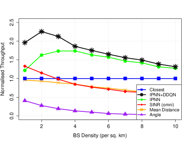
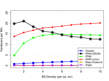
VII-B BS Density
Fig. 7 shows the impact of the BS density on the normalised throughput. At lower densities the IPNN+DDQN association scheme gives significant improvements over all of the other association schemes, although as the density increases the performance appears to converge to that of the IPNN association scheme. This reinforces our observations in the previous sub-section: at low densities a number of factors determine which of the candidate BSs the UAV should connect to, whereas as the density increases the interference power becomes the primary deciding factor, which renders the IPNN+DDQN association marginally better than the IPNN association, in terms of throughput. As before, the handover rates in Fig. 8 show that the IPNN+DDQN solution improves throughput at the expense of a higher handover rate, and that increasing the amount of interference in the environment will result in the IPNN+DDQN providing a reduced handover rate compared to the pure IPNN-based association scheme. Note that the increase in the BS density does not impact the run-time of our algorithm, as the architecture of the IPNN and DDQN modules and the number of inputs are determined by parameters such as and , which are kept constant in our analysis.
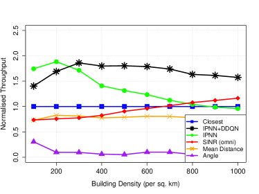
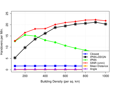
VII-C Building Density
Fig. 9 and Fig. 10 show the performance under different densities of buildings in the urban environment. Increasing the building density leads to more LoS blocking obstacles in the environment, which results in wireless channels that fluctuate significantly more as the UAV moves. The IPNN module, as it only considers aggregate interference power, struggles to adapt to this dynamism and so the normalised throughput degrades with increasing density. The IPNN+DDQN solution is aware of both interference powers as well as candidate BS powers, so it is capable of adapting to this increasing channel complexity, and manages to maintain a relatively stable performance improvement over the baseline. As a consequence of reacting to the increasingly dynamic radio environment the IPNN+DDQN solution sees an increase in the handover rate as the building density increases. We note that very densely built-up environments require very frequent handovers to respond to the volatile radio conditions.
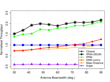
VII-D UAV Beamwidth
Fig. 11 and Fig. 12 show the effects of UAV antenna beamwidth on the performance. Increasing the beamwidth of the antenna allows more interfering BSs to be illuminated by the directional antenna, which increases the overall interference power. This appears to increase the fluctuations in interference power, as Fig. 12 shows a significant increase in the handover rate of the IPNN-based association scheme. By contrast, the DDQN association scheme is able to recognise the negative impact of these interference fluctuations and is able to intelligently avoid unnecessary handovers, thus reducing the handover rate as the beamwidth increases. It is interesting to note that the resulting normalised throughput appears to be quite similar for both REQIBA-based association schemes, as the IPNN scheme focuses on improving the channel quality at all costs, while the IPNN+DDQN may opt for a worse channel, but benefit from the reduced overheads of frequent handovers.
VII-E Handover Penalty
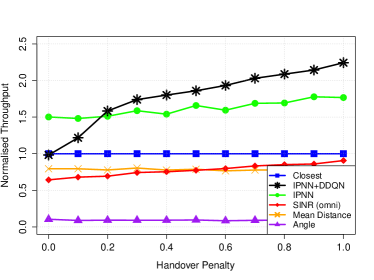
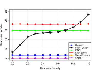
We now consider the effect of the handover penalty on the UAV performance. Recall that has a range between 0 and 1, and impacts the received reward in a timestep where a handover occurs. Values of closer to 0 correspond to heavy penalty for carrying out a handover, and this is reflected in the resulting throughput shown in Fig. 13. The figure shows that the IPNN+DDQN based association method suffers heavily for low values of . The DDQN module relies on trial-and-error exploration to learn which actions to take for a given observed state; low values of , however, heavily punish any exploration and attempts to connect to better BSs. This causes the DDQN module to learn a very conservative association policy which results in very low throughput performance, much lower than the IPNN association scheme, which ignores the impact of handover penalties entirely. It is worth noting that the IPNN scheme appears to only suffer minor throughput degradation for lower values of , despite the relatively large handover rate, as shown in Fig. 14. We can see that for low values of the IPNN+DDQN solution prioritises minimising the handover rate at all costs, while as increases the IPNN+DDQN association scheme begins to more freely carry out handovers during flight, even exceeding the handover rate of the IPNN-based association above a certain point.
VII-F Randomised Trajectory
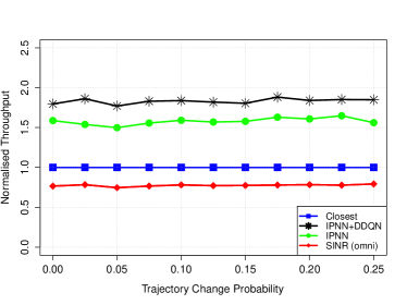
Up to now, we have assumed that the UAV flies in a straight line in each episode, as our main focus is to evaluate UAV base station association rather than path planning. To verify that our REQIBA solution works for non-linear trajectories as well, we now relax this assumption and consider randomised trajectories in each episode. At each timestep, with a certain probability the UAV will adjust its horizontal travel vector by 30 degrees either clockwise or counter-clockwise. Fig. 15 shows the resulting performance as the UAV trajectory becomes increasingly random in each episode. We note that while the randomness appears to introduce additional noise to the measurements, none of the association algorithms appear to deteriorate with the non-linear UAV movement. While the Q-Learning component of the DDQN does make predictions about future timesteps, as we use low values of the Q-value discount factor the additional randomness does not appear to affect the DDQN performance. This indicates that REQIBA is applicable to a wide variety of UAV mobility scenarios.
VIII Discussion & Conclusion
In this paper we have proposed an ML-based BS association scheme referred to as REQIBA that would allow a UAV moving through an urban area to intelligently choose which BSs to connect to, to maximise the overall data throughput during the flight while keeping the rate of handovers manageable. Our proposed solution consists of two modules: a regression neural network module for estimating the aggregate interference powers for each candidate BS’s channel, and a DDQN module for choosing the candidate BS in each timestep, based on RL training. Our numerical results show that the REQIBA solution allows a UAV to significantly improve its total throughput, when compared to the ML solution we proposed for a static UAV scenario in our prior work [16], as well as to heuristic association schemes that use the available environment information. It has been established by the wireless community that UAV wireless channels are interference-limited due to the low levels of signal blockage; we have shown that under certain conditions the interference power is such an issue that we can achieve the best throughput by simply choosing the candidate BS with the lowest interference power on its channel, without taking into account other factors such as the signal power of the candidate BSs or the effects of handovers. The use of our full REQIBA solution with the DDQN module becomes justified when the environment is less influenced by interference (such as due to lower BS density or lower UAV height above ground), and where achieving the best throughput means balancing a number of environmental factors in the decision process. Even in scenarios where the IPNN module alone is sufficient to maximise the throughput, the DDQN module plays an important role in managing the rate of handovers, as it explicitly factors in the impact of carrying out a handover to a new BS. Without this function, the UAV may carry out very frequent handovers to respond to the dynamic environmental conditions, in the order of one handover every three or four seconds according to our results.
Our analysis shows that while the REQIBA solution using the joint IPNN+DDQN association can offer significant benefits to the UAV, there are certain important caveats that need to be taken into account by the UAV operators before choosing it for the BS association task. First of all, we have demonstrated that interference power prediction is a mandatory phase of the association decision process; while the IPNN module could be used in isolation to make association decisions, the DDQN module relies on information about the interference power, and cannot provide good performance without this input. The DDQN module was also shown to react negatively to strong handover penalties, as the penalty punishes any exploration carried out by the DDQN, which causes the training process to learn to pursue a handover-minimisation scheme, giving relatively poor results. By comparison, the simpler IPNN-only association scheme was shown to be more resilient to strong handover penalties, and would be a more appropriate scheme to use in situations where the handover penalties are severe.
Ultimately, the problem of mobility management involves finding a balance between maximising the channel quality of a moving device while minimising the cost incurred by handovers. Allowing a device the flexibility of choosing its associated BS with the changing environment carries the cost of more frequent handovers. If the overheads associated with the handovers are too great, or if the UAV use-case requires low handover rates, then an ML-based association scheme may not be the most appropriate choice in some circumstances. Our results have shown that while certain heuristic association schemes (such as the highest-SINR association scheme) are wholly inappropriate for UAV connectivity, other schemes (such as closest BS association) can offer very low handover rates, and therefore may be the most suitable association schemes to adopt in some scenarios.
It should be noted that although our algorithm design was motivated by the unique challenges that UAVs experience when interacting with the cellular network, it can also be applied to terrestrial devices with only minor modifications. These modifications may include the removal of the height above ground input parameter, and the inclusion of a predicted travel vector input (as ground devices, in particular road users, have more predictable trajectories than UAVs, which could be leveraged by our algorithm for its decision-making).
In this work we have considered cellular interference mitigation by means of a steerable, directional UAV antenna, as per the 3GPP recommendations. Other interference mitigation techniques are being proposed in the state-of-the-art, such as interference coordination and cooperative beamforming [50]. In our future works we may consider a multi-agent optimisation scenario where one agent on the UAV optimises the association decisions, while another agent applies interference coordination on the side of the BSs. In future works we may also consider additional UAV parameters such as flight velocities and trajectories; this would allow us to design intelligent agents which leverage that information in their decision-making. In this work we kept the BS heights constant, but the IPNN architecture can easily be extended to incorporate variable BS heights above ground. We may explore scenarios with variable BS heights in future works. Additionally, in this work we have explored a scenario where a single UAV applied the REQIBA algorithm on its local hardware to make connectivity decisions; this scenario can be extended to consider a fleet of UAVs on a joint mission. In such a scenario the algorithm may be modified into a centralised algorithm that offloads the connectivity decisions from the individual UAVs. This would reduce the hardware requirements for the UAVs, while introducing latency challenges. Furthermore, the presence of multiple environmentally-aware UAVs may allow for additional data and experience sharing, which could create new AI-driven decision-making problems, and allow for solutions such as federated learning. We may explore these scenarios, and the performance trade-offs introduced by them, in a future work.
Acknowledgement
This material is based upon works supported by the Sci- ence Foundation Ireland under Grants No. 17/NSFC/5224 and 13/RC/2077_P2. Prof. DaSilva’s participation was supported by the Commonwealth Cyber Initiative (CCI).
Appendix: CDF of the Instantaneous SINR
| (7) |
where denotes the Nakagami-m multipath fading component with shape parameter , and . comes from the mulipath fading component having a gamma distribution, with and denoting the gamma function and the lower incomplete gamma function, respectively. comes from representing the lower incomplete gamma function as in [51][8.352.2]. comes from the substitution . comes from the Leibniz integral rule, where is the Laplace transform of . Finally, comes from the fact that following Proposition 3 in [52], where and are the aggregate interference from BSs with LoS and NLoS channels to the UAV, respectively. It follows then that the k-th derivative of can be expressed as a sum of products of higher derivatives of , , and following the general Leibniz rule.
The aggregate LoS and NLoS interferences and are random variables which are the sum of the received interference signals from sets of BSs that have the corresponding channel type to the UAV. We denote the sets of these interfering BSs as ; these are inhomogeneous PPP with intensity functions and , where denotes a probability function which gives the LoS probability of a point at to the UAV [52]. A number of LoS probability functions for UAV communications in cities have been proposed by the wireless community including Eq. (2) in [52], any of these may be applied for the derivation below.
The Laplace transform of where is derived as:
| (8) |
where stems from the aggregate interference consisting of a sum of the received signal powers from the BSs belonging to the set , with each signal affected by Nakagami-m multipath fading, where . comes from the power-series representation of the Nakagami-m multipath fading component. stems from the probability generating functional of a PPP [53]. Note that the integral is over the area of , as all interfering BSs outside of the illuminated area will give 0 interference due to the UAV directional antenna gain. For more information on the mathematical characterisation of UAV-BS connectivity, the reader is referred to our prior works [22, 23, 52].
References
- [1] CNN, “First Drone Delivery of a Donated Kidney Ends with Successful Transplant,” May 2019.
- [2] M. Mozaffari, W. Saad, M. Bennis, Y. Nam, and M. Debbah, “A Tutorial on UAVs for Wireless Networks: Applications, Challenges, and Open Problems,” IEEE Communications Surveys & Tutorials, vol. 21, no. 3, pp. 2334–2360, Third Quarter 2019.
- [3] R. Gupta, A. Kumari, S. Tanwar, and N. Kumar, “Blockchain-Envisioned Softwarized Multi-Swarming UAVs to Tackle COVID-I9 Situations,” IEEE Network Magazine, vol. 35, no. 2, pp. 160–167, March 2021.
- [4] Z. Shao, G. Cheng, J. Ma, Z. Wang, J. Wang, and D. Li, “Real-time and Accurate UAV Pedestrian Detection for Social Distancing Monitoring in COVID-19 Pandemic,” IEEE Transactions on Multimedia, April 2021.
- [5] C. O’Brien, “Manna Aero Gets First Certificate for Drone Delivery Service,” The Irish Times, May 2021. [Online]. Available: https://www.irishtimes.com/business/transport-and-tourism/manna-aero-gets-first-certificate-for-drone-delivery-service-1.4571362
- [6] C. Choi, “The Future of Drones and Wind Power,” Inside Unmanned Systems, Oct. 2020. [Online]. Available: https://insideunmannedsystems.com/the-future-of-drones-and-wind-power/
- [7] “TR 36.777: Technical Specification Group Radio Access Network; Study on Enhanced LTE Support for Aerial Vehicles (Release 15),” 3GPP, Tech. Rep., 2018.
- [8] R. Amer, W. Saad, and N. Marchetti, “Mobility in the Sky: Performance and Mobility Analysis for Cellular-Connected UAVs,” IEEE Transactions on Communications, vol. 68, no. 5, pp. 3229 – 3246, May 2020.
- [9] R. Amer, W. Saad, and N. Marchetti, “Toward a Connected Sky: Performance of Beamforming With Down-Tilted Antennas for Ground and UAV User Co-Existence,” IEEE Communications Letters, vol. 23, no. 10, pp. 1840–1844, Oct. 2019.
- [10] X. Ge, “Ultra-Reliable Low-Latency Communications in Autonomous Vehicular Networks,” IEEE Transactions on Vehicular Technology, vol. 68, no. 5, pp. 5005–5016, May 2019.
- [11] X. Lin et al., “The Sky Is Not the Limit: LTE for Unmanned Aerial Vehicles,” IEEE Communications Magazine, vol. 56, no. 4, pp. 204–210, April 2018.
- [12] “TR 36.777 Annex H : Field Trials Results on Mobility,” 3GPP, Tech. Rep., 2018.
- [13] B. Galkin et al., “Experimental Evaluation of a UAV User QoS from a Two-Tier 3.6GHz Spectrum Network,” IEEE International Conference on Communications (ICC), June 2021.
- [14] E. Fonseca, B. Galkin, M. Kelly, L. A. DaSilva, and I. Dusparic, “Mobility for Cellular-Connected UAVs: Challenges for the Network Provider,” Joint EuCNC & 6G Summit, June 2021.
- [15] European Union Aviation Safety Agency (EASA), “EU Wide Rules on Drones Published,” May 2019. [Online]. Available: https://www.easa.europa.eu/newsroom-and-events/press-releases/eu-wide-rules-drones-published
- [16] B. Galkin, R. Amer, E. Fonseca, and L. A. DaSilva, “Intelligent Base Station Association for UAV Cellular Users: A Supervised Learning Approach,” IEEE 5G World Forum, Sept. 2020.
- [17] “LTE Unmanned Aircraft Systems,” Qualcomm Technologies, Inc, Tech. Rep., 2017.
- [18] M. M. Azari, F. Rosas, and S. Pollin, “Cellular Connectivity for UAVs: Network Modeling, Performance Analysis and Design Guidelines,” IEEE Transactions on Wireless Communications, vol. 18, no. 7, pp. 3366–3381, July 2019.
- [19] J. Stanczak, I. Z. Kovacs, D. Koziol, J. Wigard, R. Amorim, and H. Nguyen, “Mobility Challenges for Unmanned Aerial Vehicles Connected to Cellular LTE Networks,” IEEE Vehicular Technology Conference (VTC Spring), June 2018.
- [20] S. Euler, H. Maattanen, X. Lin, Z. Zou, M. Bergström, and J. Sedin, “Mobility Support for Cellular Connected Unmanned Aerial Vehicles: Performance and Analysis,” IEEE Wireless Communications and Networking Conference (WCNC), April 2019.
- [21] A. Fakhreddine, C. Bettstetter, S. Hayat, R. Muzaffar, and D. Emini, “Handover Challenges for Cellular-Connected Drones,” Proc. of ACM Workshop on Micro Aerial Vehicle Networks, Systems, and Applications, pp. 9–14, June 2019.
- [22] B. Galkin, J. Kibiłda, and L. A. DaSilva, “Backhaul For Low-Altitude UAVs in Urban Environments,” in IEEE International Conference on Communications (ICC), May 2018.
- [23] R. Amer, W. Saad, B. Galkin, and N. Marchetti, “Performance Analysis of Mobile Cellular-Connected Drones under Practical Antenna Configurations,” in IEEE International Conference on Communications (ICC), June 2020.
- [24] S. Zhang, Y. Zeng, and R. Zhang, “Cellular-Enabled UAV Communication: A Connectivity-Constrained Trajectory Optimization Perspective,” IEEE Transactions on Communications, vol. 67, no. 3, pp. 2580–2604, March 2019.
- [25] J. Chen and D. Gesbert, “Optimal Positioning of Flying Relays for Wireless Networks: A LOS Map Approach,” IEEE International Conference on Communications (ICC), May 2017.
- [26] O. Esrafilian and D. Gesbert, “Simultaneous User Association and Placement in Multi-UAV Enabled Wireless Networks,” ITG Workshop on Smart Antennas (WSA), March 2018.
- [27] R. Gangula, D. Gesbert, D. F. Külzer, and J. M. Franceschi, “A Landing Spot Approach for Enhancing the Performance of UAV-Aided Wireless Networks,” IEEE International Conference on Communications Workshops (ICC Workshops), May 2018.
- [28] B. Omoniwa, B. Galkin, and I. Dusparic, “Energy-Aware Placement Optimization of UAV Base Stations via Decentralized Multi-Agent Q-Learning,” IEEE Consumer Communications & Networking Conference (CCNC), Jan. 2022.
- [29] H. Huang, Y. Yang, H. Wang, Z. Ding, H. Sari, and F. Adachi, “Deep Reinforcement Learning for UAV Navigation Through Massive MIMO Technique,” IEEE Transactions on Vehicular Technology, vol. 69, no. 1, pp. 1117–1121, Jan. 2020.
- [30] Q. Liu, L. Shi, L. Sun, J. Li, M. Ding, and F. Shu, “Path Planning for UAV-Mounted Mobile Edge Computing With Deep Reinforcement Learning,” IEEE Transactions on Vehicular Technology, vol. 69, no. 5, pp. 5723–5728, May 2020.
- [31] Z. Xiong et al., “UAV-Assisted Wireless Energy and Data Transfer With Deep Reinforcement Learning,” IEEE Transactions on Cognitive Communications and Networking, vol. 7, no. 1, pp. 85–99, Mar. 2021.
- [32] U. Challita, W. Saad, and C. Bettstetter, “Deep Reinforcement Learning for Interference-aware Path Planning of Cellular-Connected UAVs,” IEEE International Conference on Communications (ICC), May 2018.
- [33] Y. Zeng and X. Xu, “Path Design for Cellular-Connected UAV with Reinforcement Learning,” IEEE Global Communications Conference (GLOBECOM), Dec. 2019.
- [34] X. Zhong, Y. Huo, X. Dong, and Z. Liang, “Deep Q-Network Based Dynamic Movement Strategy in a UAV-Assisted Network,” IEEE Vehicular Technology Conference (VTC Fall), Dec. 2020.
- [35] M. M. U. Chowdhury, W. Saad, and I. Guvenc, “Mobility Management for Cellular-Connected UAVs: A Learning-Based Approach,” IEEE International Conference on Communications (ICC), June 2020.
- [36] A. Azari, F. Ghavimi, M. Ozger, R. Jantti, and C. Cavdar, “Machine Learning Assisted Handover and Resource Management for Cellular Connected Drones,” IEEE Vehicular Technology Conference (VTC Spring), May 2020.
- [37] Y. Chen, X. Lin, T. A. Khan, and M. Mozaffari, “A Deep Reinforcement Learning Approach to Efficient Drone Mobility Support,” Arxiv e-prints, May 2020.
- [38] A. Takács, R. Manghirmalani, H. Mahkonen, Y.-P. E. Wang, and L. Xingqin, “Methods and Systems for Using an Unmanned Aerial Vehicle (UAV) Flight Path to Coordinate an Enhanced Handover in 3rd Generation Partnership Project (3GPP) Networks,” Apr. 16 2020, US Patent App. 16/610,049.
- [39] J. Du, C. Jiang, J. Wang, Y. Ren, and M. Debbah, “Machine Learning for 6G Wireless Networks: Carrying Forward Enhanced Bandwidth, Massive Access, and Ultrareliable/Low-Latency Service,” IEEE Vehicular Technology Magazine, vol. 15, no. 4, pp. 122–134, Dec. 2020.
- [40] E. Fonseca, B. Galkin, L. A. DaSilva, and I. Dusparic, “Adaptive Height Optimisation for Cellular-Connected UAVs using Reinforcement Learning,” Arxiv e-prints, July 2020.
- [41] B. Galkin, J. Kibilda, and L. A. DaSilva, “Backhaul for Low-Altitude UAVs in Urban Environments,” IEEE International Conference on Communications (ICC), May 2018.
- [42] “Recommendation P.1410-5 ”Propagation Data and Prediction Methods Required for the Design of Terrestrial Broadband Radio Access Systems Operating in a Frequency Range From 3 to 60 GHz”,” ITU-R, Tech. Rep., 2012.
- [43] X. Xu and Y. Zeng, “Cellular-Connected UAV: Performance Analysis with 3D Antenna Modelling,” IEEE International Conference on Communications Workshops (ICC Workshops), May 2019.
- [44] M. H. C. Garcia et al., “A Tutorial on 5G NR V2X Communications,” IEEE Communications Surveys & Tutorials, February 2021.
- [45] “DJI MATRICE 300 RTK - Specifications.” [Online]. Available: https://www.dji.com/ie/matrice-300/specs
- [46] Z. Wang, T. Schaul, M. Hessel, H. Hasselt, M. Lanctot, and N. Freitas, “Dueling Network Architectures for Deep Reinforcement Learning,” International Conference on Machine Learning, June 2016.
- [47] “R Interface to Keras.” [Online]. Available: https://keras.rstudio.com/
- [48] H. Elshaer, M. N. Kulkarni, F. Boccardi, J. G. Andrews, and M. Dohler, “Downlink and Uplink Cell Association With Traditional Macrocells and Millimeter Wave Small Cells,” IEEE Transactions on Wireless Communications, vol. 15, no. 9, pp. 6244–6258, Sept. 2016.
- [49] V. François-Lavet, P. Henderson, R. Islam, M. G. Bellemare, and J. Pineau, “An Introduction to Deep Reinforcement Learning,” Foundations and Trends in Machine Learning, vol. 11, no. 3-4, 2018.
- [50] W. Mei and R. Zhang, “Cooperative Downlink Interference Transmission and Cancellation for Cellular-Connected UAV: A Divide-and-Conquer Approach,” IEEE Transactions on Communications, vol. 68, no. 2, pp. 1297–1311, Feb. 2020.
- [51] I. Gradshteyn and I. Ryzhik, Table of Integrals, Series, and Products. Academic Press, 2007.
- [52] B. Galkin, J. Kibiłda, and L. A. DaSilva, “A Stochastic Model for UAV Networks Positioned Above Demand Hotspots in Urban Environments,” IEEE Transactions on Vehicular Technology, vol. 68, no. 7, pp. 6985–6996, July 2019.
- [53] M. Haenggi, Stochastic Geometry for Wireless Networks. Cambridge University Press, 2013.
![[Uncaptioned image]](/html/2010.01126/assets/x17.png) |
Boris Galkin is currently a research fellow in CONNECT, Trinity College Dublin, Ireland. He was awarded a BAI and MAI in computer & electronic engineering in 2014 and a Ph.D. degree in 2019 from Trinity College Dublin, Ireland. His research interests include unmanned aerial vehicles, heterogeneous networks, and the application of AI and Machine Learning to 5G and Beyond networks. |
![[Uncaptioned image]](/html/2010.01126/assets/x18.png) |
Erika Fonseca is a PhD researcher at CONNECT in Trinity College Dublin. She received her MSc degree in Network Computing from University Federal Fluminense in 2017 and the BSc degree in Telecommunications Engineering in 2013, also from the University Federal Fluminense. She has experience in wireless network research and her research interest is focused on 5G cellular networks and software-defined radio. |
![[Uncaptioned image]](/html/2010.01126/assets/x19.png) |
Ramy Amer is a PhD researcher at CONNECT in Trinity College Dublin. He received the BSc and MSc degrees in Electrical Engineering from the Alexandria University, Egypt, in 2010, and 2016, respectively. His research interests include cross layer design, cognitive radio, wireless caching, and energy harvesting. |
![[Uncaptioned image]](/html/2010.01126/assets/x20.png) |
Luiz A. DaSilva is the Executive Director of the Commonwealth Cyber Initiative (CCI), and Bradley Professor of Cybersecurity at Virginia Tech. He was previously the Professor of Telecommunications (personal chair) at Trinity College Dublin. Until March 2020, he served as the Director of CONNECT, the telecommunications research centre funded by the Science Foundation Ireland. His research focuses on distributed and adaptive resource management in wireless networks, and in particular cognitive radio networks and the application of game theory to wireless networks. |
![[Uncaptioned image]](/html/2010.01126/assets/x21.png) |
Ivana Dusparic is an Ussher Assistant Professor in the School of Computer Science and Statistics at Trinity College Dublin since 2016. She holds a BSc from La Roche College, PA, USA (2003), and MSc (2005) and PhD (2010) from Trinity College Dublin. Her expertise and research interests lie in the use of Artificial Intelligence techniques (reinforcement learning, multi-agent systems) to achieve autonomous optimization of large-scale heterogeneous infrastructures, applied to smart cities and sustainable urban mobility. |