Robust edge states in magnetic domain-wall racetrack
Abstract
Controllable artificial pinning is indispensable in numerous domain-wall (DW) devices, such as memory, sensor, logic gate, and neuromorphic computing hardware. The high-accuracy determination of the effective spring constant of the pinning potential, however, remains challenging, because the extrinsic pinning is often mixed up with intrinsic ones caused by materials defects and randomness. Here, we study the collective dynamics of interacting DWs in a racetrack with pinning sites of alternate distances. By mapping the governing equations of DW motion to the Su-Schrieffer-Heeger model and evaluating the quantized Zak phase, we predict two topologically distinct phases in the racetrack. Robust edge state emerges at either one or both ends depending on the parity of the DW number and the ratio of alternating intersite lengths. We show that the in-gap DW oscillation frequency has a fixed value which depends only on the geometrical shape of the pinning notch, and is insensitive to device imperfections and inhomogeneities. We propose to accurately quantify the spring coefficient that equals the square of the robust DW frequency multiplied by its constant mass. Our findings suggest as well that the DW racetrack is an ideal platform to study the topological phase transition.
Introduction.—Magnetic domain walls (DWs) AtkinsonNM2003 ; CatalanRMP2012 ; KoyamaNM2011 have attracted tremendous recent attention owing to their fundamental nature and potential applications AllwoodS2005 ; XuNN2008 ; OmariPRA2014 ; LuoN2020 ; OnoAPE2008 ; BisigAPL2009 ; HeAPL2007 ; MartinezPRB2011 ; ParkinS2008 ; ParkinNN2015 ; UmmelenSR2017 ; PolenciucAPL2014 ; ShenAPL2018 ; ZhangAPL2014 ; BoriePRA2017 . To achieve a reliable control of the DW position in spintronic devices, engineered pinning sites are often introduced by artificial notches HayashiPRL2006 ; LepadatuPRL2009 ; DolocanAPL2014 ; YuanPRB2014 ; BedauPRL2008 , protrusions ZengAPL2009 ; LewisAPL2011 ; ChangAPL2012 ; FranchinPRB2011 ; PetitJAP2008 , kinks GlathePRB2012 , etc. It has been shown that the shape and strength of pinning potential can strongly affect the DW dynamics AkermanPRB2010 . For instance, a critical current must be overcome to depin the DW HeJAP2005 ; RavelosonaPRL2005 . The approach was adopted as well to quantify the spin-transfer torque (STT) non-adiabaticity LepadatuPRB2009 ; LepadatuPRB2010 , an important quantity for current-induced DW motion while its true value is still highly controversial LepadatuPRB2009 ; LepadatuPRB2010 ; MeierPRL2007 ; MoriyaNPhys2008 ; HeynePRL2010 ; ThomasN2006 ; BisigPRL2016 . One reason for the inconsistency reported in experiments may come from the lack of reliable determination of the pinning potential.
In principle, by measuring the oscillation frequency of a pinned DW, one can obtain the strength of the confining potential ThomasN2006 . However, the extrinsically engineered pinning is often mixed up with the intrinsic ones originating from materials defects and randomness JiangPRB2013 ; BadeaPRA2016 , leading to a seemingly insuperable difficulty to distinguish the two contributions. A high-accuracy determination of the profile of the pinning potential is therefore vital not only for a consistent and deep understanding of the STT physics but also for an efficient and reliable design of DW-based spintronic devices. Topology theory often bridges the gap between the global and local characteristics of a physical system. One of the most outstanding examples is the quantum Hall effect Klitzing1980 , which defines a resistance that depends only on fundamental physical constants due to the robust in-gap edge states, making possible an accurate and standardized definition of the ohm. It thus motivates us to pursue a topological method for the realization of the DW-frequency standard that is immune from the intrinsic disorder and defects.
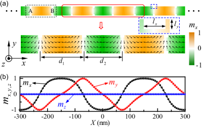
In this work, we theoretically investigate the collective dynamics of DWs that are locally pinned by notches with alternate distances in a magnetic nanostrip racetrack [see Fig. 1(a)]. Without loss of generality, we consider the Nel-type DW in the setup. The governing equation of DW motion is mapped to the Su-Schrieffer-Heeger model that allows a topological description. By evaluating the quantized Zak phase, we predict two topologically distinct phases in the racetrack. The bulk-boundary correspondence dictates a robust DW oscillation at the racetrack edges. We show that the oscillating frequency of the edge DW has a constant value which depends only on the geometrical shape of the pinning notch, and is insensitive to material imperfection and inhomogeneity. We perform full micromagnetic simulations to verify theoretical predictions with a great agreement. Our results offer the standard of the DW oscillation frequency and suggest as well that the magnetic DW racetrack is an ideal platform to study the fundamental topological phase and phase transition, in addition to its practical application in information technology.
Model.—We start with the Landau-Lifshitz-Gilbert equation that governs the DW dynamics ZhangPRL2004 ; ThiavilleEPL2005 :
| (1) |
where is the unit magnetization vector with the saturated magnetization , is the gyromagnetic ratio, and is the Gilbert damping constant. The effective field comprises the external field, the exchange field, the magnetic anisotropic field, and the dipolar field. is the torque due to the spin-transfer or spin-orbit effects. For the case of STT, with and being the flow direction of the spin-polarized current. Here is the charge current density, is the spin polarization, is the -factor, is the Bohr magneton, and is the (negative) electron charge.
The collective-coordinate or method provides a simple, yet accurate description of the motion of complex DWs [see Fig. 1(b)], in terms of its position and tilting angle WalkerJAP1974 ; LiPRB2004 :
| (2) | ||||
where the collective coordinates and are the position and tilt angle of the -th DW, respectively, includes the pinning field from both the notch and the DW-DW interaction, and are the demagnetizing factors along the - and -axis of the nanostrip, respectively, and represents the DW width with the exchange stiffness, the magnetocrystalline anisotropy constant, and being the vacuum permeability. Since we are interested in the genuine oscillation of DW near the pinning notch, we have assumed that the spin torque is absent in Eq. (2), while its response to this stimuli can be straightforwardly analyzed (see below).
From the energy point of view, can be expressed as the spatial derivative of the total potential:
| (3) |
where and are the width and thickness of the nanostrip, respectively, and is the total energy of the system including both the pinning potential due to the notches and the coupling between DWs: . Here is the spring constant determined by the shape of the notch and is the coupling constant depending on the distance between DWs. Generally, the DW-DW interaction energy can be divided into three parts: the monopole-monopole (), the exchange (), and the dipole-dipole () PivanoPRB2020 . The explicit form of can be obtained from micromagnetic simulations in a self-consistent manner. Considering a small and neglecting the dissipation terms, we arrive at the linear form of Eq. (2):
| (4) |
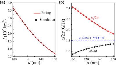
where the is the effective mass of a single DW with , and is the set of the nearest neighbors of . We thus have () when and share an intracellular (intercellular) connection with . Here, and are alternating intersite lengths. The governing equation is thus mapped to a Su-Schrieffer-Heeger problem SuPRL1979 . To obtain the analytical formula of , we simulate the dynamic of a DW-DW pair separated by an arbitrary distance (see Supplemental Material Suppl for details). Symbols in Fig. 2(a) are numerical results and the solid curve is the best fitting , with J m-1, J, and J m. Figure 2(b) plots the -dependence of the out-of-phase and in-phase DW-oscillation frequencies, that is, and respectively, in the simple two-DW system. It shows that increases while decreases for an increasing . One naturally expects that when , with corresponding to the oscillation frequency of an isolated DW. By measuring in experiments, one can determine the pinning-potential stiffness . This approach, however, suffers from an issue that the dynamics of a single DW can be easily modified by structure defects and material randomness, and it thus cannot precisely determine the genuine profile of the pinning potential.
Topological phase in DW racetrack.—For the one-dimensional DW lattice plotted in Fig. 1(a), the dashed black rectangle represents the unit cell, and the basis vector is with . The band structure of the collective DW oscillations can be computed by a plane wave expansion , where for different sublattices, is an integer, and is the wave vector. The Hamiltonian then can be expressed in momentum space as:
| (5) |
Solving (5) gives the dispersion relation:
| (6) |
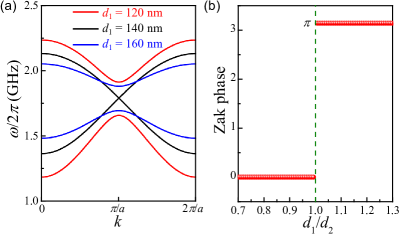
where represents the optical (acoustic) branch. The bulk band structures for different geometric parameters are plotted in Fig. 3(a), where is fixed to nm if not stated otherwise and magnetic parameters of Ni are adopted Suppl . For , the two bands merge together [black curve in Fig. 3(a)], while a gap opens at when [red and blue curves in Fig. 3(a)], leading to an insulating phase. To judge if these insulating phases are topological, we consider the Zak phase ZakPRL1985 , a topological invariant that can be evaluated by integrating the Berry connection over the first Brillouin zone:
| (7) |
where is the Bloch wave function of the energy band. Figure 3(b) shows the dependence of the Zak phase on the ratio . It is observed that is quantized to 0 when and to otherwise, indicating two topologically distinct phases in the two regions. We point out that this conclusion is independent of the choice of .
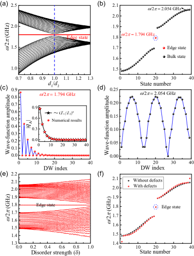
Bulk-boundary correspondence indicates the existence of robust edge states. To verify this point, we compute the spectrum of a finite racetrack containing an odd number (e.g., 39) of DWs. Numerical results are shown in Fig. 4(a), where the in-gap state (red line) emerges for all ratios . We first consider the case . Figure 4(b) plots the eigenfrequencies of the system, showing that there is one in-gap mode marked by red dot. Further, it is found that its spatial distribution is highly localized at the left end of the racetrack [see Fig. 4(c)], in contrast to its bulk counterpart shown in Fig. 4(d). We adopt the Ansätze for the localized mode as with . The edge state then can be solved by the equations:
| (8) | ||||
with the boundary condition (A-site DW is in the outmost left boundary). Because , we obtain and . The wave-function amplitude of A-site DWs therefore follows an exponentially decaying formula for . Analytical result agrees excellently with numerical calculations, as plotted in the inset of Fig. 4(c). We point out that the edge state becomes localized in the right end instead if (not shown). Interestingly, the localized modes emerge in both ends as the magnetic racetrack contains an even number of DWs (detailed calculations can be found in Supplemental Material Suppl ).
To verify the topological robustness of the edge states, we calculate the spectrum of the DW racetrack including disorder and defects, with results presented in Figs. 4(e) and 4(f), respectively. Here the disorder is introduced by assuming that the coupling parameters and have a random variation, i.e., , , with the disorder strength and a uniformly distributed random number between and 1. As to the defects, we assume and suffering from a shift (, ) on the second and fourth DWs. From Figs. 4(e) and 4(f), we observe that the edge state is very robust against these disorder and defects, while the bulk states are sensitive to them.
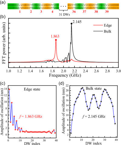
Micromagnetic simulations.—To confirm our theoretical predictions, we use the micromagnetic package MUMAX3 VansteenkisteAdv2014 to simulate the dynamics of interacting DWs in Ni nanostrip of length nm, as shown in Fig. 5(a) Suppl . To obtain the spectra of DW oscillations, a sinc-function magnetic field is applied for 1 s along the -axis with mT, GHz, and ns. The position of all DWs is recorded every 100 ps, where we define with the integration confined at the -th DW. Here, is adopted as the weight function based on the fact that the closer to the center of DW, the greater the component of the magnetization.
To find the frequency range of the edge and bulk states, we analyze the temporal Fourier spectra of the DW racetrack at two different positions (DW 1 and DW 20, for example). Figure 5(b) shows the results, with peaks of the red and black curves denoting the positions of edge and bulk bands, respectively. We then apply a sinusoidal magnetic field with mT over the whole system to excite the edge and bulk modes by choosing two frequencies GHz and GHz, respectively, as marked in Fig. 5(b). The spatial distribution of DW oscillation amplitude for these two modes are plotted in Figs. 5(c) and 5(d), respectively, from which one can clearly identify the localized and extended nature of edge and bulk states, respectively. Full micromagnetic simulations are thus well consistent with the analytical results but with the following discrepancies: (i) The oscillation amplitude of B-site DWs does not exactly vanishes as dictated by the analytical theory, but is promoted by A-site DW oscillations. We attribute it to the anharmonic DW-DW interaction Suppl ; (ii) A finite DW oscillation is observed in the deep bulk of the racetrack, as opposed to an exponential decay to zero. However, we note that the DW oscillation amplitude in such case is smaller than the mesh size (2 nm) adopted in the micromagnetic simulations. It is thus still within the numerical accuracy.
Discussion and conclusion.—By including the STT term in Eq. (2), we find that it does not change the spectrum of the collective DW oscillations, but causes a global shift to the equilibrium DW position Suppl . It is noted that the imaging of the DW position is already within current technology reach. Since the DW oscillation frequency can be standardized by the topological method, we are able to accurately quantify the STT non-adiabaticity coefficient by experimentally measuring the slope of curve.
In summary, we studied the Su-Schrieffer-Heeger problem in a one-dimensional DW racetrack with periodic pinning notches. Zak phase was evaluated to derive the phase diagram that allows two topologically distinct phases separated by the phase transition point at an identical intercellular and intracellular length between neighbouring DWs. The emerging edge state dictated by the bulk-boundary correspondence was shown to be particularly robust against moderate defects and disorder. Analytical results were well supported by full micromagnetic simulations. We propose that the uncovered topological feature can be utilized as the DW frequency standard, which shall encourage our experimental colleagues to accurately measure the pinning profile and to finally resolve the controversy about the parameter. Our findings suggest as well that the DW racetrack offers an ideal platform to explore the fundamental topological phase, such as the higher-order topological corner (hinge) states in two-(three-)dimensional structures, and the nonlinear effect in topological phase transition, which are interesting issues for future study.
Acknowledgements.
This work was supported by the National Natural Science Foundation of China (NSFC) (Grants No. 12074057, No. 11604041, and No. 11704060). Z.-X. Li acknowledges financial support from the China Postdoctoral Science Foundation (Grant No. 2019M663461) and the NSFC (Grant No. 11904048). Z. Wang was supported by the China Postdoctoral Science Foundation under Grant No. 2019M653063.References
- (1) D. Atkinson, D. A. Allwood, G. Xiong, M. D. Cooke, C. C. Faulkner, and R. P. Cowburn, Magnetic domain-wall dynamics in a submicrometre ferromagnetic structure, Nat. Mater. 2, 85 (2003).
- (2) G. Catalan, J. Seidel, R. Ramesh, and J. F. Scott, Domain wall nanoelectronics, Rev. Mod. Phys. 84, 119 (2012).
- (3) T. Koyama, D. Chiba, K. Ueda, K. Kondou, H. Tanigawa, S. Fukami, T. Suzuki, N. Ohshima, N. Ishiwata, Y. Nakatani, K. Kobayashi, and T. Ono, Observation of the intrinsic pinning of a magnetic domain wall in a ferromagnetic nanowire, Nat. Mater. 10, 194 (2011).
- (4) D. A. Allwood, G. Xiong, C. C. Faulkner, D. Atkinson, D. Petit, and R. P. Cowburn, Magnetic domain-wall logic, Science 309, 1688 (2005).
- (5) P. Xu, K. Xia, C. Gu, L. Tang, H. Yang, and J. Li, An all-metallic logic gate based on current-driven domain wall motion, Nat. Nanotech. 3, 97 (2008).
- (6) K. A. Omari and T. J. Hayward, Chirality-based vortex domain-wall logic gates, Phys. Rev. Appl. 2, 044001 (2014).
- (7) Z. Luo, A. Hrabec, T. P. Dao, G. Sala, S. Finizio, J. Feng, S. Mayr, J. Raabe, P. Gambardella, and L. J. Heyderman, Current-driven magnetic domain-wall logic, Nature (London) 579, 214 (2020).
- (8) T. Ono and Y. Nakatani, Magnetic domain wall oscillator, Appl. Phys. Express 1, 061301 (2008).
- (9) A. Bisig, L. Heyne, O. Boulle, and M. Kläui, Tunable steady-state domain wall oscillator with perpendicular magnetic anisotropy, Appl. Phys. Lett. 95, 162504 (2009).
- (10) J. He and S. Zhang, Localized steady-state domain wall oscillators, Appl. Phys. Lett. 90, 142508 (2007).
- (11) E. Martinez, L. Torres, and L. Lopez-Diaz, Oscillator based on pinned domain walls driven by direct current, Phys. Rev. B 83, 174444 (2011).
- (12) S. S. P. Parkin, M. Hayashi, and L. Thomas, Magnetic domain-wall racetrack memory, Science 320, 190 (2008).
- (13) S. Parkin and S.-H. Yang, Memory on the racetrack, Nat. Nanotech. 10, 195 (2015).
- (14) F. Ummelen, H. Swagten, and B. Koopmans, Racetrack memory based on in-plane-field controlled domain-wall pinning, Sci. Rep. 7, 833 (2017).
- (15) I. Polenciuc, A. J. Vick, D. A. Allwood, T. J. Hayward, G. Vallejo-Fernandez, K. O’Grady, and A. Hirohata, Domain wall pinning for racetrack memory using exchange bias, Appl. Phys. Lett. 105, 162406 (2014).
- (16) M. Shen, Y. Zhang, L. You, and X. Yang, Readable racetrack memory via ferromagnetically coupled chiral domain walls, Appl. Phys. Lett. 113, 152401 (2018).
- (17) Y. Zhang, W. S. Zhao, J.-O. Klein, C. Chappert, and D. Ravelosona, Current induced perpendicular-magnetic-anisotropy racetrack memory with magnetic field assistance, Appl. Phys. Lett. 104, 032409 (2014).
- (18) B. Borie, A. Kehlberger, J. Wahrhusen, H. Grimm, and M. Kläui, Geometrical dependence of domain-wall propagation and nucleation fields in magnetic-domain-wall sensors, Phys. Rev. Appl. 8, 024017 (2017).
- (19) M. Hayashi, L. Thomas, C. Rettner, R. Moriya, X. Jiang, and S. S. P. Parkin, Dependence of Current and Field Driven Depinning of Domain Walls on Their Structure and Chirality in Permalloy Nanowires, Phys. Rev. Lett. 97, 207205 (2006).
- (20) S. Lepadatu, A. Vanhaverbeke, D. Atkinson, R. Allenspach, and C. H. Marrows, Dependence of Domain-Wall Depinning Threshold Current on Pinning Profile, Phys. Rev. Lett. 102, 127203 (2009).
- (21) V. O. Dolocan, Domain wall pinning and interaction in rough cylindrical nanowires, Appl. Phys. Lett. 105, 162401 (2014).
- (22) H. Y. Yuan and X. R. Wang, Domain wall pinning in notched nanowires, Phys. Rev. B 89, 054423 (2014).
- (23) D. Bedau, M. Kläui, M. T. Hua, S. Krzyk, U. Rüdiger, G. Faini, and L. Vila, Quantitative Determination of the Nonlinear Pinning Potential for a Magnetic Domain Wall, Phys. Rev. Lett. 101, 256602 (2008).
- (24) H. T. Zeng, D. Read, D. Petit, A. V. Jausovec, L. O’Brien, E. R. Lewis, and R. P. Cowburn, Combined electrical and magneto-optical measurements of the magnetization reversal process at a domain wall trap, Appl. Phys. Lett. 94, 103113 (2009).
- (25) E. R. Lewis, D. Petit, L. O’Brien, A.-V. Jausovec, H. T. Zeng, D. E. Read, and R. P. Cowburn, Kinetic depinning of a magnetic domain wall above the Walker field, Appl. Phys. Lett. 98, 042502 (2011).
- (26) L. J. Chang, P. Lin, and S. F. Lee, Current induced localized domain wall oscillators in NiFe/Cu/NiFe submicron wires, Appl. Phys. Lett. 101, 242404 (2012).
- (27) M. Franchin, A. Knittel, M. Albert, D. S. Chernyshenko, T. Fischbacher, A. Prabhakar, and H. Fangohr, Enhanced spin transfer torque effect for transverse domain walls in cylindrical nanowires, Phys. Rev. B 84, 094409 (2011).
- (28) D. Petit, A.-V. Jausovec, D. Read, and R. P. Cowburn, Domain wall pinning and potential landscapes created by constrictions and protrusions in ferromagnetic nanowires, J. Appl. Phys. 103, 114307 (2008).
- (29) S. Glathe and R. Mattheis, Magnetic domain wall pinning by kinks in magnetic nanostripes, Phys. Rev. B 85, 024405 (2012).
- (30) J. Akerman, M. Muñoz, M. Maicas, and J. L. Prieto, Stochastic nature of the domain wall depinning in permalloy magnetic nanowires, Phys. Rev. B 82, 064426 (2010).
- (31) J. He, Z. Li, and S. Zhang, Current-driven domain-wall depinning, J. Appl. Phys. 98, 016108 (2005).
- (32) D. Ravelosona, D. Lacour, J. A. Katine, B. D. Terris, and C. Chappert, Nanometer Scale Observation of High Efficiency Thermally Assisted Current-Driven Domain Wall Depinning, Phys. Rev. Lett. 95, 117203 (2005).
- (33) S. Lepadatu, M. C. Hickey, A. Potenza, H. Marchetto, T. R. Charlton, S. Langridge, S. S. Dhesi, and C. H. Marrows, Experimental determination of spin-transfer torque nonadiabaticity parameter and spin polarization in permalloy, Phys. Rev. B 79, 094402 (2009).
- (34) S. Lepadatu, J. S. Claydon, C. J. Kinane, T. R. Charlton, S. Langridge, A. Potenza, S. S. Dhesi, P. S. Keatley, R. J. Hicken, B. J. Hickey, and C. H. Marrows, Domain-wall pinning, nonadiabatic spin-transfer torque, and spin-current polarization in permalloy wires doped with vanadium, Phys. Rev. B 81, 020413(R) (2010).
- (35) G. Meier, M. Bolte, R. Eiselt, B. Krüger, D. Kim, and P. Fischer, Direct Imaging of Stochastic Domain-Wall Motion Driven by Nanosecond Current Pulses, Phys. Rev. Lett. 98, 187202 (2007).
- (36) R. Moriya, L. Thomas, M. Hayashi, Y. B. Bazaliy, C. Rettner, and S. S. P. Parkin, Probing vortex-core dynamics using current-induced resonant excitation of a trapped domain wall, Nat. Phys. 4, 368 (2008).
- (37) L. Heyne, J. Rhensius, D. Ilgaz, A. Bisig, U. Rüdiger, M. Kläui, L. Joly, F. Nolting, L. J. Heyderman, J. U. Thiele, and F. Kronast, Direct Determination of Large Spin-Torque Nonadiabaticity in Vortex Core Dynamics, Phys. Rev. Lett. 105, 187203 (2010).
- (38) L. Thomas, M. Hayashi, X. Jiang, R. Moriya, C. Rettner, and S. S. P. Parkin, Oscillatory dependence of current-driven magnetic domain wall motion on current pulse length, Nature (London) 443, 197 (2006).
- (39) A. Bisig, C. A. Akosa, J.-H. Moon, J. Rhensius, C. Moutafis, A. von Bieren, J. Heidler, G. Kiliani, M. Kammerer, M. Curcic, M. Weigand, T. Tyliszczak, B. Van Waeyenberge, H. Stoll, G. Schütz, K.-J. Lee, A. Manchon, and M. Kläui, Enhanced Nonadiabaticity in Vortex Cores due to the Emergent Hall Effect, Phys. Rev. Lett. 117, 277203 (2016).
- (40) W. Jiang, Y. Fan, P. Upadhyaya, M. Lang, M. Wang, L.-T. Chang, K. L. Wong, J. Tang, M. Lewis, J. Zhao, L. He, X. Kou, C. Zeng, X. Z. Zhou, R. N. Schwartz, and K. L. Wang, Mapping the domain wall pinning profile by stochastic imaging reconstruction, Phys. Rev. B 87, 014427 (2013).
- (41) R. Badea and J. Berezovsky, Mapping the landscape of domain-wall pinning in ferromagnetic films using differential magneto-optical microscopy, Phys. Rev. Appl. 5, 064003 (2016).
- (42) K. v. Klitzing, G. Dorda, and M. Pepper, New Method for High-Accuracy Determination of the Fine-Structure Constant Based on Quantized Hall Resistance, Phys. Rev. Lett. 45, 494 (1980).
- (43) S. Zhang and Z. Li, Roles of Nonequilibrium Conduction Electrons on the Magnetization Dynamics of Ferromagnets, Phys. Rev. Lett. 93, 127204 (2004).
- (44) A. Thiaville, Y. Nakatani, J. Miltat, and Y. Suzuki, Micromagnetic understanding of current-driven domain wall motion in patterned nanowires, Europhys. Lett. 69, 990 (2005).
- (45) N. L. Schryer and L. R. Walker, The motion of 180° domain walls in uniform dc magnetic fields, J. Appl. Phys. 45, 5406 (1974).
- (46) Z. Li and S. Zhang, Domain-wall dynamics driven by adiabatic spin-transfer torques, Phys. Rev. B 70, 024417 (2004).
- (47) A. Pivano and V. O. Dolocan, Analytical description of the topological interaction between magnetic domain walls in nanowires, Phys. Rev. B 101, 014438 (2020).
- (48) W. P. Su, J. R. Schrieffer, and A. J. Heeger, Solitons in Polyacetylene, Phys. Rev. Lett. 42, 1698 (1979).
- (49) See Supplemental Material at http://link.aps.org/supplemental for the determination of in a DW-DW pair, the edge state calculations for an even number of DWs, the details of micromagnetic simulations, the anharmonic effect, and the STT effect on the DW motion, which includes Ref. AharoniJAP1998 .
- (50) A. Aharoni, Demagnetizing factors for rectangular ferromagnetic prisms, J. Appl. Phys. 83, 3432 (1998).
- (51) J. Zak, Berry’s Phase for Energy Bands in Solids, Phys. Rev. Lett. 62, 2747 (1989).
- (52) A. Vansteenkiste, J. Leliaert, M. Dvornik, M. Helsen, F. Garcia-Sanchez, and B. V.Waeyenberge, The design and verification of MuMax3, AIP Adv. 4, 107133 (2014).