RCM: Requirement Capturing Model for Automated Requirements Formalisation
Abstract
Most existing automated requirements formalisation techniques require system engineers to (re)write their requirements using a set of predefined requirement templates with a fixed structure and known semantics to simplify the formalisation process. However, these techniques require understanding and memorising requirement templates, which are usually fixed format, limit requirements captured, and do not allow capture of more diverse requirements. To address these limitations, we need a reference model that captures key requirement details regardless of their structure, format or order. Then, using NLP techniques we can transform textual requirements into the reference model. Finally, using a suite of transformation rules we can then convert these requirements into formal notations. In this paper, we introduce the first and key step in this process, a Requirement Capturing Model (RCM) - as a reference model - to model the key elements of a system requirement regardless of their format, or order. We evaluated the robustness of the RCM model compared to 15 existing requirements representation approaches and a benchmark of 162 requirements. Our evaluation shows that RCM breakdowns support a wider range of requirements formats compared to the existing approaches. We also implemented a suite of transformation rules that transforms RCM-based requirements into temporal logic(s). In the future, we will develop NLP-based RCM extraction technique to provide end-to-end solution.
1 INTRODUCTION
Formal verification techniques requires system requirements to be expressed in formal notations [Buzhinsky, 2019]. However, the majority of critical system requirements are still predominantly written in informal notations (textual or natural languages - NL), which are inherently ambiguous and have incomplete syntax and semantics [Lúcio et al., 2017b, Sládeková, 2007]. To automate the formalisation process, several bodies of work within the literature focused on proposing pre-defined requirement templates, patterns [Justice, 2013], boilerplates [Mavin et al., 2009], and structured control English [R. S. Fuchs, 1996], to express one system requirement sentence while eliminating the ambiguities. Such templates have complete syntax to ensure the feasibility of transforming textual requirements into formal notations using a suite of manually crafted, template-specific transformation rules (e.g., [Yan et al., 2015]). However, some of the predefined templates are domain dependent and are hard to generalise [Rupp, 2009], or can only capture limited subsets of requirements structures [R. S. Fuchs, 1996]. In addition, most existing formalisation algorithms are customized for transforming system requirements to one target formal language. Thus, a need to transform the same requirements into different formal languages mandates significant rework of the formalisation algorithm.
Complementary to this research direction, instead of considering introducing new sentence-based templates covering a wider range of requirements and complicating the requirements specification process, we introduce a Requirement Capturing Model (RCM), as a reference model that defines the key properties that make up a system behavioral requirement sentence, regardless of the syntactic structure of these properties, lexical-words, or their order. RCM separates the writing styles (format and structure) from the abstract requirement properties and the formal notations. Our new RCM model thus enables us to: (1) represent a much wider range of requirements that have differing count, order or types of properties, by identifying the specific properties in the input requirement sentence to generic RCM defined properties; (2) specify requirements in a wide variety of different formats, extremely useful to avoid re-writing existing requirements; (3) formalize requirements into different formal notations through mapping RCM properties to those of the target formal notation; and (4) enable use of NLP-based requirements extraction techniques to transform textual requirements into the RCM-based requirements model. with the key elements to be extracted now clearly defined and known. Our key contributions in this paper are:
-
•
Introduce RCM as a reference model and intermediate representation between informal and formal notations. RCM was developed based on extensive review of existing requirements templates, patterns, CNL, etc in the literature, with a view to support automatic transformation into formal notations.
-
•
A suite of transformation rules from RCM to Metric Temporal Logic (MTL), to demonstrate how an RCM-based requirements model can be transformed into formal notations.
-
•
Evaluation of the representation power of RCM by comparing it to 15 other existing approaches using 162 behavioral requirements for critical systems synthesized from the literature. We provide the RCM representation and corresponding automatically generated (MTL and CTL) formal notations for each of these requirements.
2 MOTIVATION
Jen is a system engineer working for an automotive company. She wants to specify the requirements of one of the system modules - a small excerpt is shown in Table 1 - while making sure that these requirements can be easily transformed into formal notations as a mandatory compliance requirement. Jen decided to check the existing requirement specification techniques in the literature to choose which one covers most of her requirements. Jen researched existing requirements formalisation techniques, see the related work section for these techniques, and outlined her trials to use these techniques to model her requirements after rephrasing some of her requirements to suit existing templates.
| RQ1: R_STATUS shall indicate the rain sensor. It shall be ON, when the external environment is raining. |
| Techniques: Universal pattern [Teige et al., 2016], Structured English [Konrad and Cheng, 2005], Rup’s boilerplates [Rupp, 2009], ACE[R. S. Fuchs, 1996], EARS[Mavin et al., 2009], CFG[Sládeková, 2007] and BTC[Justice, 2013] |
| RQ2: When the external environment rains for 1 minute, the wipers shall be activated within 30 seconds until the rain sensor equals OFF. |
| Techniques: Universal pattern [Teige et al., 2016] and BTC[Justice, 2013] |
| RQ3: While the wipers are active, the wipers speed shall be readjusted every 20 seconds. |
| Techniques: Structured English [Konrad and Cheng, 2005] |
Jen found that none of the existing techniques she found can be used to cover all her requirements. She then had to learn and use all these templates and have these tools all running. Furthermore, Jen found that the majority of these solutions rely on pre-defined formats and structure of requirements boilerplates. This mandates (1) a fixed order of requirement components/sub-components, (2) a fixed English-syntax for a specific component/sub-component, (3) a fixed/small set of English verbs or other lexical words. Thus, Jen needs to rewrite her requirements to confirm the defined format which puts more overhead on her especially if the defined formats are limited and cannot be extended to new scenarios.
Taking into consideration all combinations of styling, ordering, and omission/existence of different requirements model properties will increase the size of the defined formats. Consequently this will increase the complexity of using them by system engineers and the complexity of the parsing algorithms needed to transform them to formal models. Furthermore, most existing formalization techniques apply on-the fly transformation on the given structured requirement sentences to generate formal notations. These transformations are hard-coded or tightly customized according to the target formal notation properties and formats. It would be much more useful if the common parts are computed once and transformed to intended notations as needed.
3 Related Work
Many requirements formalisation approaches assume requirements are specified in a constrained natural language (CNL) with specific style, format and structure to be able to transform into formal notations - e.g. [Ghosh et al., 2016, Nelken and Francez, 1996, Michael et al., 2001, Holt and Klein, 1999, Ambriola and Gervasi, 1997, Sturla, 2017, Pease and Li, 2010]. These CNL are meant to avoid natural language related quality problems (e.g., ambiguity inconsistency, etc.) and increase the viability of automating the formalisation process.
CNL is a restricted form of NL especially created for writing technical documents as defined in [Kittredge, 2003] with the aim to reduce/avoid NL problems (e.g., ambiguity inconsistency, .etc). CNL typically has a defined sub-set of NL grammar, lexicon and/or sentence structure [Kuhn, 2014]. Different forms of CNL are also provided as a reliable solution for requirements representation. Fuchs et al. [R. S. Fuchs, 1996] propose Attempto Controlled English (ACE) with a restricted list of verbs, nouns and adjectives for the requirement set in addition to restrictions on the structure of the sentence. ACE can be transformed into Prolog. ACE can handle requirements with condition and action components. Multiple CNLs are proposed later inspired by ACE (e.g., Atomate language [Van Kleek et al., 2010], PENG[Schwitter, 2002]) for formal generation purposes and for other purposes (e.g., BioQuery-CNL [Erdem and Yeniterzi, 2009], OWL ACE [Kaljurand and Fuchs, 2006]).
Similarly to ACE, Scott and Cook[Scott et al., 2004] presented Context Free Grammars (CFGs) for requirement specification. Although the format of the requirement components is more limited than ACE with additional restrictions on words, it covers time-related properties. Yan et al. [Yan et al., 2015] presented a more flexible CNL with constraints on the word set such that, a clause should contain (1) single word noun as a subject and a verb predicate with one of the following formats ”verb be+(gerundparticiple) be+complement”, (2) the complement should be adjective or adverbial word, (3) prepositional phrases are not allowed except ”in + time point” at the end of the clause. The CNL does not consider time information except pre-elapsed time.
Boilerplates are also widely used. These provide a fixed syntax and lexical words with replaceable attributes. Boilerplates are more limited than CNL and require adaptation to different domains. In [Rupp, 2009], a constrained RUP’s boilerplate is provided which can handle a limited range of requirements. EARS [Mavin et al., 2009] boilerplates are less restricted and can support a wider range of requirements. Esser et al. [Esser and Struss, 2007] proposed a suite of requirement templates (TBNLS) with support mapping to propositional logic with temporal relations. For validating the conformity of the written requirement and the boilerplate, authors in [Arora et al., 2013, Arora et al., 2014] provide checking techniques.
Requirement patterns provide a more flexible solution. However, When a new requirement structure is added, a new pattern should be created for it, which increases the size of the patterns set. In [Teige et al., 2016] a universal pattern was presented to support many requirements formats (trigger, then action). They then introduced additional time-based kernel patterns in [Justice, 2013]. Although these patterns cover many requirement properties, they do not still cover the possible combinations of the supported properties eligible to one requirement specification. In addition, the approach lack complex time properties - e.g. In-between-time and pre-elapsed-time properties. Dwyer et al. [Dwyer et al., 1999] proposed several patterns applicable for non-real-time requirement specifications. These patterns are categorized into two major groups: occurrence patterns and order patterns, while considering scopes (e.g., globally, before R, after R) for a given specification pattern. The work is extended later in [Konrad and Cheng, 2005] to cope with real-time requirement specifications. The real time patterns considers versions of the pre-elapsed-time, in-between-time and valid-time information for the action component.
Event-Condition-Action (ECA) was initially proposed in active databases area to express behavioral requirements. ECA became widely used by several researchers in diffident areas. An ECA rule assumes that when an event E occurs, the condition C will be evaluated, and if true, the action A will be executed. ECA notations have been extended to capture time information [Qiao et al., 2007]. However, ECA rules do not support (e.g., factual rules), and do not consider scopes for action and the time notations apply on events.
Despite extensive research and industrial use, all of these alternatives including CNL, patterns, boilerplates and ECA have downsides including: (1) users need guidance on how to phrase requirements in terms of CNL; (2) expressiveness is reduced by the available subset of natural language used; and (3) they are restricted to certain domains or pre-defined subsets of requirements properties. RCM subsumes and builds on the key properties (components) introduced in all of these techniques, but with enough detail and flexibility to facilitate the requirements formalisation as discussed below.
| Property | Description | |
| Trigger | is an event that initiates action(s) (e.g., ”when the system halts” in Fig.3). This component type is ubiquitous throughout the requirements of most critical systems. | |
| Condition | is a constraint that should be satisfied to allow a specific system action(s) to happen (e.g., ”if X is ON” in Fig.3). In contrast to triggers, the satisfaction of the condition should be checked explicitly by the system. The system is not concerned with ”when the constraint is satisfied” but with ”is the constraint satisfied or not at the checking time” to execute the action (e.g., in the previous example ”X” might remain ”ON” for a while and have no effect on the system until checked for. | |
| Component | Action | is a task that should be accomplished by the system in response to triggers and/or constrained by conditions (e.g., ”M should be set to TRUE” in Fig.3). In case that, a primitive requirement consists of an action component only, it would be marked as a factual rule expressing factual information about the system (e.g., The duration of a flashing cycle is 1 second [Houdek, 2013]). |
| Req-scope |
determines the context under which (i) ”condition(s) and trigger(s)” can be valid – called a pre-conditional scope as it is linked to the condition or trigger; and (ii) ”action(s)” can occur – called an action scope, as it applies only on the action. The scope may define the starting boundary or the ending one (e.g., ”after sailing termination”, ”before B_sig is True” in Fig.3).
Fig.3 presents the main variations for starting/ending a context (e.g., None, after operational constraint is true, until operational constraint becomes true or before operational constraint becomes true). Other alternatives can be expressed by the main variation. For example, ”while R is true” can be expressed by after and until as ”after R is true” and ”until not R”. It is worth noting that, ”Before” and ”Until” define the same end of the valid period which is ”R is true”. ”Until” mandates the precondition(s)/action(s) to hold till ”R is true”, but ”Before” does not care about their status.
![[Uncaptioned image]](/html/2009.14683/assets/x1.png)
|
|
| Valid-time | represent the valid time period of the given component (e.g., in ”the vehicle warns the driver by acoustical signals for 1 second” the action is hold for 1 second length of time [Houdek, 2013]). Valid-time can be a part of any component. | |
| Sub-Component | Pre-elapsed-time | is the consumed time length from an offset point –before an action to occur or a condition to be checked (e.g., ”After less than 2 seconds” in Fig.3). This type is only eligible to action and condition components. |
| In-between-time | express the length of time between two consecutive events to occur in the repetition case (e.g., ”every 1 seconds” in Fig.3). Such sub-component type is eligible to action and trigger components as indicated in Fig.2. | |
| Hidden constraint | allows an explicit constraint to be defined on a specific operand within a component. For example, in ”if the camera recognizes the lights of an advancing vehicle, the high beam headlight that is activated is reduced to low beam headlight within 5 second”[Houdek, 2013]. The that is activated is a constraint defined on the operand the high beam headlight). | |
4 REQUIREMENT CAPTURING MODEL
In this section, we present the details of the Requirements Capture Model (RCM). First, we explain the process we followed to develop the RCM. Then, we describe the RCM Model and the key components of the model. Third, we describe how to transform RCM to formal notations. Finally, we describe how to construct RCM from input textual requirements. It is important to note that this last step is out of the scope of this project, and thus we do not include all the details of the extraction process and we do not cover the evaluation of the extraction algorithm in this paper.
4.1 RCM Development Process
To identify the key requirement properties we needed to support in a generic reference model for safety-critical requirements, we reviewed a large number of natural language-based critical system requirements collected from many sources: [Jeannet and Gaucher, 2016, Thyssen and Hummel, 2013, Fifarek et al., 2017, Lúcio et al., 2017a, Dick et al., 2017, Bitsch, 2001, Teige et al., 2016, Lúcio et al., 2017b, Mavin et al., 2009, R. S. Fuchs, 1996, Rolland and Proix, 1992, Macias and Pulman, 1995] and 15 requirement representation approaches listed in Table.3.
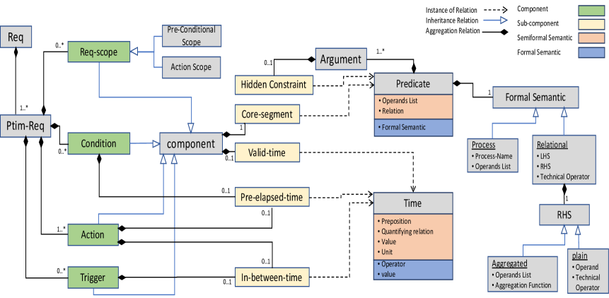
We identified 19 distinct properties that we grouped into 8 abstract properties (4 components and 4 sub-components). These are listed with their description in Table.2. Fig.1 shows a manually crafted example requirement that reflects most of these components and sub-components used through the properties description for a better understanding.
Properties Codes A:action / C:condtion / T:trigger / hidden:Hidden-constraint / SP:pre-cond Startup-phase / EP:pre-cond Endup-Phase / SA:action Startup-phase / EA:action Endup-phase / vt:valid-time / pt:pre-elapsed-time / rt:in-between-time
| Approach | Requirement properties | |||||||||||||||||||
| Action | Condition | Trigger | Req-Scope | |||||||||||||||||
| Code | Source | A | A-vt | A-rt | A-pt | C | C-vt | C-pt | T | T-vt | T-rt | SP | SP-vt | EP | EP-vt | SA | SA-vt | EA | EA-vt | Hidden |
| A1 | BTC [Justice, 2013, Teige et al., 2016] | 1 | 1 | 1 | 1 | 1 | 1 | 1 | 1 | 1 | 1 | |||||||||
| 1 | 1 | 1 | 1 | 1 | 1 | 1 | 1 | 1 | 1 | |||||||||||
| A2 | EARS [Mavin et al., 2009] | 1 | 1 | 1 | ||||||||||||||||
| 1 | 1 | 1 | ||||||||||||||||||
| 1 | 1 | 1 | ||||||||||||||||||
| A3 | EARS-CTRL [Lúcio et al., 2017b] | 1 | 1 | 1 | 1 | |||||||||||||||
| A4 | ECA [Van Kleek et al., 2010] | 1 | 1 | 1 | 1 | 1 | 1 | 1 | 1 | 1 | ||||||||||
| A5 | boilerplates [Rupp, 2009] | 1 | 1 | |||||||||||||||||
| 1 | 1 | |||||||||||||||||||
| A6 | Safety templates [Fu et al., 2017] | 1 | 1 | 1 | 1 | 1 | ||||||||||||||
| 1 | 1 | 1 | 1 | 1 | 1 | |||||||||||||||
| 1 | 1 | 1 | 1 | 1 | ||||||||||||||||
| A7 | Req Lang [Marko et al., 2015] | 1 | 1 | 1 | 1 | 1 | 1 | |||||||||||||
| A8 | CFG [Scott et al., 2004, Sládeková, 2007] | 1 | 1 | 1 | ||||||||||||||||
| 1 | 1 | 1 | ||||||||||||||||||
| 1 | 1 | 1 | ||||||||||||||||||
| 1 | 1 | 1 | ||||||||||||||||||
| A9 | ACE [R. S. Fuchs, 1996] | 1 | 1 | 1 | ||||||||||||||||
| A10 | PENG [Schwitter, 2002] | 1 | 1 | 1 | 1 | 1 | 1 | 1 | 1 | |||||||||||
| A11 | Structured English [Yan et al., 2015] | 1 | 1 | 1 | 1 | 1 | 1 | 1 | 1 | |||||||||||
| A12 | TBNLS [Esser and Struss, 2007] | 1 | 1 | 1 | 1 | 1 | 1 | 1 | ||||||||||||
| A13 | Real-time [Konrad and Cheng, 2005] | 1 | 1 | 1 | 1 | |||||||||||||||
| 1 | 1 | 1 | 1 | |||||||||||||||||
| 1 | 1 | 1 | 1 | |||||||||||||||||
| 1 | 1 | 1 | 1 | 1 | ||||||||||||||||
| 1 | 1 | 1 | 1 | 1 | ||||||||||||||||
| 1 | 1 | 1 | 1 | 1 | ||||||||||||||||
| A14 | Dawyer [Dwyer et al., 1999] | 1 | 1 | 1 | 1 | 1 | ||||||||||||||
| A15 | Pattern_based Req [Berger et al., 2019] | 1 | 1 | 1 | 1 | 1 | ||||||||||||||

We then analysed 15 of the existing approaches (outlined in the related work section) against these 19 requirement properties as presented in Table.3. The approaches (rows) are encoded A1 to A15, and requirement properties are encoded as columns. An approach can be represented in more than one row. This reflects that some approaches might support multiple properties, but these properties cannot be used in the same requirement – the template or pattern does not support having certain properties in one requirement. The cell value equals ”1” if the property is supported in this template.
This table does not reflect the limitations/restrictions that these approaches apply on a given property formatting or order - i.e. condition must come before action, or scope comes before condition. Our analysis of this table illustrates that: (1) no approach covers all requirement properties possibly because this would make it too complex to use; (2) almost all approaches support action components as a core element; (3) approaches A1: Btc[Justice, 2013] and A11: Structured-English[Konrad and Cheng, 2005] are the most expressive approaches as they cover majority of the properties; and (4) the valid-time property for the StartUp and the EndUP phases of the pre-conditional scope is not supported by any of these approaches although its appearance in the analysed requirements.
4.2 RCM Domain Model
The RCM is designed to capture the requirements properties listed above while relaxing the ordering and formatting restrictions presented by the existing techniques. In RCM, a system is represented as a set of requirements R. Each requirement represented by one RCM and may have one or more primitive requirements PR where { = and n0}. Each represents only one requirement sentence, and may include condition(s), trigger(s), action(s) and requirement scope(s). The detailed meta-model structure of the RCM to one requirement is presented in Fig.2.
The figure shows that a primitive requirement is composed of four requirement component types: condition, trigger, action and requirement scope. Except for action(s), the existence of each of these components is optional in a primitive requirement. A requirement component has a component core-segment that expresses the main portion of the component, and optionally could also have a valid-time: the component’s valid time-length. The pre-elapsed-time sub-component can only appear with a condition or action component. An in-between-time sub-component can only appear with Trigger or Action components according to the reviewed scenarios (e.g., requirements and representation formats). A hidden-constraint is an optional sub-component to an operand. To store this information without loss, RCM stores the hidden constraint inside the relevant operand object as indicated in Fig.2. This structure is intrinsic to allow the nested hidden constraints. For example, ”the entry of A1 whose index is larger than the first value in A2 that is larger than S1 shall be set to 0”.
All five sub-components are instances of either Predicate or Time structure. The Predicate structure consists of the operands, the operator and negation flag/property (e.g., in ”if X exceeds 1” the ”X” and ”1” are the operands and ”exceeds” is the operator in the semi-formal semantic and ”” is the operator in the formal semantic). The Time structure stores the unit, value and quantifying relation (e.g., ”for less than 2 seconds”, ”2” and ”seconds” are the unit and value respectively, ”less than” is the semi-formal quantifying relation whose formal semantic is ””). Since the Predicate and Time structures are the infrastructure of the entire properties, they are designed to encapsulate the semi-formal and formal semantic allowing mappability to multiple TL. The details of formal semantic are described in section.4.3.2.
Components with the same type can be stored as a tree –the most suitable to keep nested relation appropriately, where leafs are the components, and inner nodes are coordinating relationships (e.g., check the conditions components of PR[1] in Fig.3).
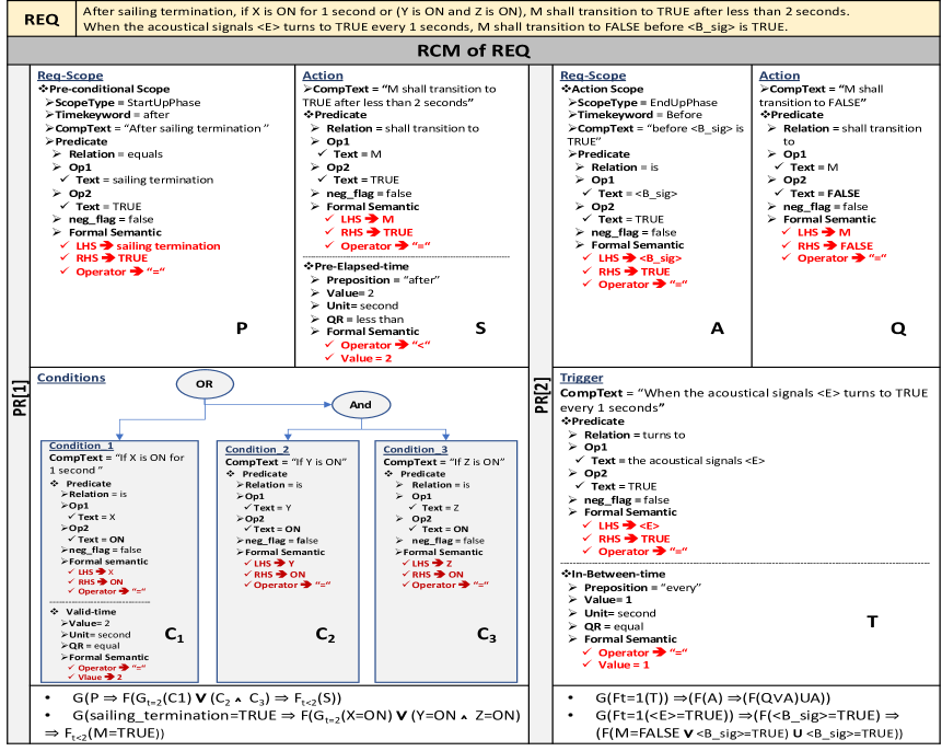
Example RCM: Fig.3 shows the RCM representation of the REQ example. REQ has two primitive requirements. PR[1] constituting of five components {”After sailing termination”, ”if X is ON for 1 second”, ”Y is ON”, ”Z is ON”, and ”M shall transition to TRUE after less than 2 seconds”}. PR[2] has three components {”When the acoustical signals E turns to TRUE every 1 seconds”, ”M shall transition to FALSE”, and ”before B_sig is TRUE”}. Components of each primitive requirement are presented in separate blocks in the figure. In each block, sub-components (predicates and time structures) are separated by horizontal line. The figure also highlights the encapsulation of semi-formal semantic (in black) and formal semantic (in red). Components with the same type (e.g., conditions in PR[1]) are represented by tree structure. In addition, the MTL representation of each primitive requirement is provided, see subSection.4.3.3
4.3 RCM Transformation
In this section, we illustrate transformation into temporal logic (TL)- as an example of formal notations. We first illustrate: (1) the mapping between the RCM to TL, and (2) the formalization of the RCM infrastructure (i.e., Predicate and Time structures). Then, we provide the transformation process.
| RCM | TL Mapping | ||||||
| Properties (component/ subcomponents) | Versions | Applicable on | MTL | CTL | |||
| Action | 1 | A: do something | A | A | |||
| Pre-condition | Condition | 2 | If S | Action (P in mapping) | Temporal Modality | ||
| Trigger | 3 | When S | |||||
| Conditions and triggers | 4 | When S, IF Q | Q) | Q) | |||
| Req-Scope: (Preconditional-Scope / Action-Scope) | StartUP | 5 | After S | Precondition/ action (P in mapping) | |||
| EndUP | 6 | Before S | |||||
| 7 | Until S | ||||||
| StartUP and EndUp | 8 | After Q & Before S Between Q and S | |||||
| 9 | After Q Until S & While Z {Q=Z&S= Z} | ||||||
| Pre-elapsed-time | 10 | After c time | Condition/ Action (P in mapping) | Time notation | |||
| 11 | after at-most c time | ||||||
| 12 | after at-least c time | ||||||
| 13 | after less-than c time | ||||||
| 14 | after greater-than c | ||||||
| Validation-time | 15 | for c time | Condition/ Trigger/ Action (P in mapping) | ||||
| 16 | for at-most c time | ||||||
| 17 | for at-least c time | ||||||
| 18 | for less-than c time | ||||||
| 19 | for greater-than c | ||||||
| In-between-time | 20 | every c time | Action/ Trigger (P in mapping) | ||||
| 21 | every at-most c time | ||||||
| 22 | every at-least c time | ||||||
| 23 | every less-than c time | ||||||
| 24 | every greater-than c | ||||||
| Hidden-Constraint | 25 | Whose S | P is Any component | bran | |||
| ching | |||||||
4.3.1 RCM and Temporal Logic
In order to formally model a given requirement represented by RCM in temporal logic (TL), we have to define a set of transformation rules. A TL formula is built from a finite set of proposition variables AP by making use of boolean connectives (e.g., ”AND”, ”OR”) and the temporal modalities (e.g., U (until)) [Haider, 2015, Brunello et al., 2019]. Within such formula, each proposition letter is expressed by a true/false statement and may be attached with time notation in some versions of temporal logic (e.g., MTL). Consider the following sentence:”After the button is pressed, the light will turn red until the elevator arrives at the floor and the doors open[Brunello et al., 2019]”. Such sentence can be captured by the following TL formula:
where p, q, s, and v are proposition variables corresponding to ”the button being pressed”, ”the light turning red”, ”the elevator arriving”, and ”the doors opening”, respectively.
We use the following to build the mapping between RCM and TL:
-
1.
Propositions and time notations: Given that, RCM components and sub-components are expressed as predicates or time structures as indicated in Fig.2. These structures are eventually mapped to proposition and time notations in the corresponding temporal logic formula (e.g., the action component ”M shall transition to TRUE after less than 2 seconds” mapped to ”(S)”, where S and ”t2” represent the predicate in bold and time phrase underlined).
-
2.
Coordinating relations: The booleans connecting propositions can be obtained from coordinating relations connecting multiple components with the same types. Such relations are represented by tree for each component type as discussed before (e.g., the condition components ”X is ON for 1 second or (Y is ON and Z is ON)” mapped to ””.
-
3.
Temporal modality: The temporal modalities can be identified based on the component type (e.g., the type of the component ”After sailing termination” is ”pre-conditional-scope startup-phase” mapped to ””
To demonstrate the robustness of the RCM and capability to transform to different formal notations, we provide here a mapping into two examples of temporal logic, Metric Temporal Logic (MTL) [Alur and Henzinger, 1993, Koymans, 1990] and CTL [Clarke and Emerson, 2008], as shown in Table 4 as a proof of multiple map-ability. We chose these notations as they are widely used in model checking as indicated in [Konur, 2013] and [Frappier et al., 2010, Haider, 2015] respectively. We base our temporal-modality and time-notation mapping on the mapping done in [Konrad and Cheng, 2005].
The first column in the Table.4 shows the RCM properties (components and sub-components) employed in formal roles, each attached with alternatives if any (e.g., The pre-conditions may be conditions, triggers, or both of them based on the given requirement). Possible structures corresponding to each property version are listed in the third column (i.e., the used keywords (e.g., when) are just examples, any replaceable keyword could be used). The fourth column indicates which components can be linked to each property type. The MTL and CTL representations of each property are presented in the fifth and sixth columns respectively, where these notations are grouped based on their formal types in the last column.
MTL is a real-time extension of linear-time temporal logic (LTL) [Szałas, 1995]. It has time notations and temporal operator. MTL consists of propositional variables, logical operator (e.g., , , and ), temporal operators (e.g., until ) where I is an interval of time. In addition, MTL has a timed-version of always, eventually operators. However, it doesn’t handle point intervals (e.g., [, ] as indicated in [Konur, 2013]). MTL assumes the existence of external and discrete clock updates constantly (fictitious-clock model as discussed in [Alur, 1991]).
Complementary to MTL that models linear systems, CTL model the system in a tree-like structure (i.e, there are multiple paths, any one of them might be an actual path that is realized) but it does not support time notations. In CTL, If and are formulas, then so are , , , AG, EG, A[ U ], and E[ U ], were, A and E means ”along All paths (Inevitably)” and ”there-exist one path (possibly)” respectively. CTL could determine if a given artifact possesses safety properties (e.g., ”all possible executions of a program avoid undesirable condition”).
4.3.2 RCM and Formal Semantics
Temporal logic has multiple versions exhibiting slight differences. In order to support the transformation to multiple versions with minimal adjustment in the transformation technique, RCM encapsulates formal semantics with semi-formal semantics. Design-wise, RCM augments the formal semantic in the basic units, predicate and time structures in Fig.2, that are mapable to temporal logic, as indicated in the previous subsubsection. The formal semantic of a predicate covers three formats:
-
•
Process format: is suitable to predicates express functions or process (e.g., ”the monitor sends a request to the station” ”send(themonitor, the_station,)”).
-
•
Relational format with plain RHS: the type is suitable for assignment predicates (e.g., ”set X to True” ”X = True”), comparison predicates (e.g., ”If X exceeds Y” ”X Y”) and changing state predicates (e.g., ”the window shall be moving up” ”the_window = moving-UP”).
-
•
Relational format with aggregated RHS: this format is similar to the previous one but the RHS is expressed with aggregating function (e.g., ”If the fuel level is less than the min value of Thr1 and Thr2” ”the_fuel_level ”min(Thr1, Thr2)”).
Similarly, the formal semantic is added to time structure in which the technical time operator (e.g., {}) is identified (e.g., ”for at least 2 seconds” ”t 2”).
![[Uncaptioned image]](/html/2009.14683/assets/x5.png)
4.3.3 RCM Transformation Algorithm
To accomplish the automatic transformation from RCM-to-MTL, we use the mapping rules provided in Table 4 on the obtained formal semantics of the given primitive requirements. Algorithm 1 shows the automatic transformation pseudo-code annotated in Fig.4 with each step output for PR[1] in the REQ Fig.3.
First, we get the formal semantics of each component according to Subsection.4.3.2. Then, we compute the formal semantics of the entire tree (i.e., leaf nodes represent components and inner nodes represent logical relations as discussed before) of each component type through the recursive function aggRel. After that, we construct the main parts of the formula (i.e., preCondtions, LHS and RHS) in Step3 and 4 with the help of RCM-to-MTL mapping rules in Table 4. Finally, we generate the entire formula based on the bound sides either ”LHS RHS” or ”RHS” as in Step5.
5 EVALUATION
5.1 Benchmark Datasets
We evaluate the coverage of our proposed RCM on 162 requirement sentences. These requirements were extracted from existing case studies in the literature and grouped into three sub datasets as follows: (1) expressiveness dataset (81 requirements): these are requirements collected from papers that introduced different requirement templates and formats in different domains and considering different writing styles in [Justice, 2013] [Jeannet and Gaucher, 2016][Thyssen and Hummel, 2013], [Fifarek et al., 2017], [Lúcio et al., 2017a], [Dick et al., 2017], [Bitsch, 2001], [Teige et al., 2016], [Lúcio et al., 2017b], [Mavin et al., 2009], [R. S. Fuchs, 1996], (2) formalisation dataset (28 requirements): these are requirements extracted from papers that introduced requirement formalisation techniques including [Ghosh et al., 2016, Yan et al., 2015] with total of 28 requirements and (3) online sources (43 requirements): these are requirements extracted from an online available critical-system requirements including [Houdek, 2013]. These requirements are available from 111 Dataset:https://github.com/ABC-7/RCM-Model/tree/master/dataSet.
Fig.5 presents the percentages of each of the 19 requirement properties (components/sub-components) within the entire dataset. The figure shows that time-based and hidden constraints existed in a few requirements compared to the key requirement components such as action, trigger, and condition. Overall, the distribution of the properties is biased towards the popular properties that exist in most approaches.
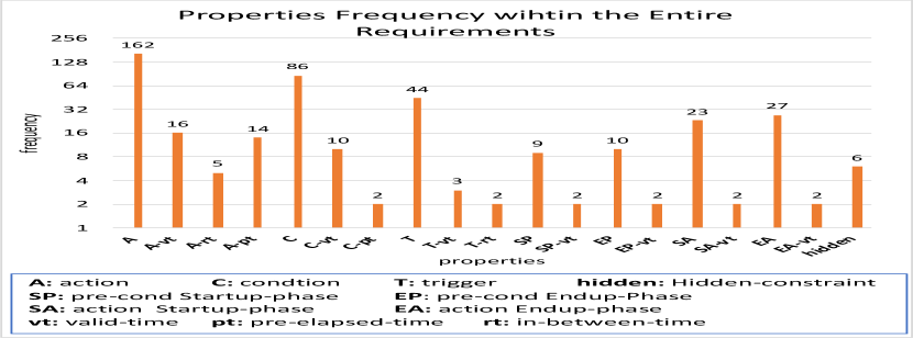
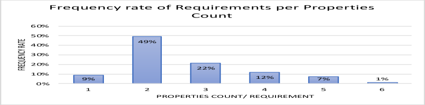
Fig.6 shows the relative complexity of the 162 requirements. We grouped the requirements based on the count of their existing properties (i.e., number of properties per requirement increases , its complexity increases ). The following examples show two requirements with one and six properties respectively, where each property is separately underlined: (1) ”the monitor mode shall be initialized to INIT”, and (2) ”after X becomes TRUE for 2 seconds, when Z turns to 1 for 1 second, Y shall be set to TRUE every 2 seconds”. In Fig.6, each group represents the count of properties regardless of the type of the property - i.e., R1: requirement with condition and action, and R2: requirement with trigger and action, both have 2 properties). For each group, we calculated the percentage of requirements. Fig.6 presents the properties count used for each requirements group on the x-axis and the corresponding requirements percentage on the y-axis. This shows that a large portion of the entire requirements sentences 9%, 49% and 22%, only consist of one, two and three properties respectively. On the other hand, 20% of the requirements sentences consist of more than three properties.
5.2 Evaluation Experiments
Experiment1. RCM expressiveness. We evaluated our proposed RCM reference model’s ability to capture and represent the requirements in our test dataset compared to 15 exiting approaches in Table.3. To do this, we manually labelled all the requirements in the dataset against the 19 requirement properties we identified in section 4. After that, we wrote a script to check each requirement (identified properties) against all existing approaches to assess if the approach provides a boilerplate or a template that supports representing the requirement or not. The results are available online 222Approaches representations, and evaluation: https://github.com/ABC-7/RCM-Model/blob/master/Approaches-Evaluation.xlsx. Fig.7 summarises the results of our analysis as percentage of the test requirements that each approach supports.
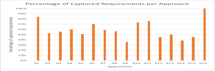
This shows that none of the existing 15 approaches is able to represent the entire dataset of requirements. This is mainly for two reasons: (1) missing properties in the used templates e.g., A1 does not support StartUp-phase Pre-conditional scope (SP), or (2) restrictions on the included properties in a requirement format e.g., A2:EARS does not support the existence of the trigger (core-segment) and a ReqScope (core-segments) using the same format. In addition, 4% of the test requirements were not covered by any of these approaches combined. An example is ”if the maximum deceleration is [insufficient] before a collision with the vehicle ahead, the vehicle warns the driver by acoustical signals for 1 seconds every 2 seconds”, where the existing properties are: condition (core-segment), StatrtUp-phase Pre-conditional scope (SP core-segment), action (core-segment), action valid-time (Vt) , and action in-between-time (Rt). These properties do not exist together in the same representation of any of the 15 approaches, see Table 3.
In contrast, our proposed RCM requirements model can represent all of the 162 requirements sentences. This is because it covers all properties that exist in the other approaches and puts no restriction on the included properties in one requirement (i.e., any property could exist in the requirement format).
Existing approaches require extension in two cases: (1) considering new requirement properties, and (2) considering new formats i.e, defining a set of properties that can exist together in one format regulated by customized grammatical rules. In contrast, since RCM covers all properties of the other approaches and more and puts no constraints on properties used in requirement, it is powerful enough to represent all requirements that can be represented by all the other approaches. It can also be used in other scenarios not currently supported by any of the 15 approaches, due to the fact that it does not enforce any restriction on the input requirement formats.
RCM does however have two main limitations: (1) it is designed for behavioral requirements of critical systems –based on the known templates,CNLs and formats used for formalization as illustrated in subsection.4.2, and (2) it requires NL-extraction techniques i.e., the current NL-extraction processes primitive requirements expressed in one sentence.
Experiment2: RCM to formal notations We applied our RCM-to-MTL and RCM-to-CTL transformation rules to the dataset of the 162 requirements. In this experiment, we used our NLP tool to extract RCM from the textual representation of the 162 requirements (out of scope of this paper). We then manually reviewed all the extracted RCM models, fixed all the broken RCM extractions manually. Once we had the full list of 162 RCM models, we applied the RCM-to-Formal transformation ruless as outlined in Section 4. We then manually reviewed all the generated formal notations. The full list of RCMs representation and the corresponding automatically generated MTL and CTL formulas is available online 333RCM-Representation and formal-notation: https://github.com/ABC-7/RCM-Model/tree/master/RCM-Auto-Transformation.
We successfully transformed 156 out of the 162 requirement RCM models into MTL notations. The other 6 requirements were partially correct. These 6 requirements turned out to involve hidden constraints expressed with and properties with a branching structure that is not supported by MTL, since it is linear. For example, the requirement ”the cognitive threshold of a human observer shall be set to a deviation that is less than 5. [Houdek, 2013]” was correctly represented in RCM, but the generated MTL is partially correct ”G(the cognitive threshold of a human observer = the deviation)”. The correct generation should be ”AG(( deviation5) (the cognitive threshold of a human observer = deviation))” provided by CTL.
Similarly, CTL could represent requirements with hidden constraints correctly, but it provides partial solutions for requirements with time notation e.g., validation-time, pre-elapsed-time and in-between-time. In total, it is capable of representing 120 requirements correctly and provides partial solutions 42 ones due the inclusion of time notation (e.g., the requirement ”if air_ok signal is low, auto control mode is terminated within 3 sec” has a partially correct generated CTL formal ”AG([air_ok signal = low] [auto control mode.crrStatus = terminated])”, but the correct formula should be G([air_ok signal = low] [Ft=3(auto control mode.crrStatus = terminated)]) provided by MTL.
6 SUMMARY
We introduced a new requirements capturing model - RCM - that represents an abstract and intermediate representation of safety-critical system requirements. RCM defines a wide range of key requirement elements and attributes that may exist in an input requirement. The model allows for standardising the textual requirements extraction process, simplifies the transformation rules to convert requirements to formal notations, and more importantly avoids re-writing existing requirements which is a complex and error prone task. We compared the coverage of our RCM model to 15 existing requirements modelling approaches using 162 diverse requirements curated from the literature. Our results show that RCM can capture a wider range of requirements compared to others due to its separation of concerns of source natural language requirements input format from reference model representation. In addition, we provided a suite of RCM-to-MTL transformation rules and presented the corresponding automatically generated MTL representation of the evaluation dataset. For our future work, we are developing an automated requirements extraction technique to populate RCM from textual requirements in addition to requirements quality checking and visualising tool of the system RCM models.
REFERENCES
- Alur, 1991 Alur, R. (1991). Techniques for automatic verification of real-time systems. PhD thesis, stanford university.
- Alur and Henzinger, 1993 Alur, R. and Henzinger, T. A. (1993). Real-time logics: Complexity and expressiveness. Information and Computation, 104(1):35–77.
- Ambriola and Gervasi, 1997 Ambriola, V. and Gervasi, V. (1997). Processing natural language requirements. In Automated Software Engineering, 1997. Proceedings., 12th IEEE International Conference, pages 36–45. IEEE.
- Arora et al., 2013 Arora, C., Sabetzadeh, M., Briand, L., Zimmer, F., and Gnaga, R. (2013). Rubric: A flexible tool for automated checking of conformance to requirement boilerplates. In Proceedings of the 2013 9th Joint Meeting on Foundations of Software Engineering, pages 599–602. ACM.
- Arora et al., 2014 Arora, C., Sabetzadeh, M., Briand, L. C., and Zimmer, F. (2014). Requirement boilerplates: Transition from manually-enforced to automatically-verifiable natural language patterns. In Requirements Patterns (RePa), 2014 IEEE 4th International Workshop on, pages 1–8. IEEE.
- Berger et al., 2019 Berger, P., Nellen, J., Katoen, J.-P., Abraham, E., Waez, M. T. B., and Rambow, T. (2019). Multiple analyses, requirements once: simplifying testing & verification in automotive model-based development. arXiv preprint arXiv:1906.07083.
- Bitsch, 2001 Bitsch, F. (2001). Safety patterns—the key to formal specification of safety requirements. In International Conference on Computer Safety, Reliability, and Security, pages 176–189. Springer.
- Brunello et al., 2019 Brunello, A., Montanari, A., and Reynolds, M. (2019). Synthesis of ltl formulas from natural language texts: State of the art and research directions. In 26th International Symposium on Temporal Representation and Reasoning (TIME 2019). Schloss Dagstuhl-Leibniz-Zentrum fuer Informatik.
- Buzhinsky, 2019 Buzhinsky, I. (2019). Formalization of natural language requirements into temporal logics: a survey. In 2019 IEEE 17th International Conference on Industrial Informatics (INDIN), volume 1, pages 400–406. IEEE.
- Clarke and Emerson, 2008 Clarke, E. M. and Emerson, E. A. (2008). Design and synthesis of synchronization skeletons using branching time temporal logic. In 25 Years of Model Checking, pages 196–215. Springer.
- Dick et al., 2017 Dick, J., Hull, E., and Jackson, K. (2017). Requirements engineering. Springer.
- Dwyer et al., 1999 Dwyer, M. B., Avrunin, G. S., and Corbett, J. C. (1999). Patterns in property specifications for finite-state verification. In Proceedings of the 21st international conference on Software engineering, pages 411–420.
- Erdem and Yeniterzi, 2009 Erdem, E. and Yeniterzi, R. (2009). Transforming controlled natural language biomedical queries into answer set programs. In Proceedings of the BioNLP 2009 Workshop, pages 117–124.
- Esser and Struss, 2007 Esser, M. and Struss, P. (2007). Obtaining models for test generation from natural-language-like functional specifications. In International workshop on principles of diagnosis, pages 75–82.
- Fifarek et al., 2017 Fifarek, A. W., Wagner, L. G., Hoffman, J. A., Rodes, B. D., Aiello, M. A., and Davis, J. A. (2017). Spear v2. 0: Formalized past ltl specification and analysis of requirements. In NASA Formal Methods Symposium, pages 420–426. Springer.
- Frappier et al., 2010 Frappier, M., Fraikin, B., Chossart, R., Chane-Yack-Fa, R., and Ouenzar, M. (2010). Comparison of model checking tools for information systems. In International Conference on Formal Engineering Methods, pages 581–596. Springer.
- Fu et al., 2017 Fu, R., Bao, X., and Zhao, T. (2017). Generic safety requirements description templates for the embedded software. In 2017 IEEE 9th International Conference on Communication Software and Networks (ICCSN), pages 1477–1481. IEEE.
- Ghosh et al., 2016 Ghosh, S., Elenius, D., Li, W., Lincoln, P., Shankar, N., and Steiner, W. (2016). Arsenal: automatic requirements specification extraction from natural language. In NASA Formal Methods Symposium, pages 41–46. Springer.
- Haider, 2015 Haider, A. (2015). A survey of model checking tools using ltl or ctl as temporal logic and generating counterexamples.
- Holt and Klein, 1999 Holt, A. and Klein, E. (1999). A semantically-derived subset of english for hardware verification. In Proceedings of the 37th annual meeting of the Association for Computational Linguistics on Computational Linguistics, pages 451–456. Association for Computational Linguistics.
- Houdek, 2013 Houdek, F. (2013). System requirements specification automotive system cluster(elc and acc). Technical University of Munich.
- Jeannet and Gaucher, 2016 Jeannet, B. and Gaucher, F. (2016). Debugging embedded systems requirements with stimulus: an automotive case-study.
- Justice, 2013 Justice, B. (2013). Natural language specifications for safety-critical systems. Master’s thesis, Carl von Ossietzky Universität.
- Kaljurand and Fuchs, 2006 Kaljurand, K. and Fuchs, N. E. (2006). Bidirectional mapping between owl dl and attempto controlled english. In International Workshop on Principles and Practice of Semantic Web Reasoning, pages 179–189. Springer.
- Kittredge, 2003 Kittredge, R. I. (2003). Sublanguages and controlled languages. In The Oxford Handbook of Computational Linguistics 2nd edition.
- Konrad and Cheng, 2005 Konrad, S. and Cheng, B. H. (2005). Real-time specification patterns. In Proceedings of the 27th international conference on Software engineering, pages 372–381. ACM.
- Konur, 2013 Konur, S. (2013). A survey on temporal logics for specifying and verifying real-time systems. Frontiers of Computer Science, 7(3):370–403.
- Koymans, 1990 Koymans, R. (1990). Specifying real-time properties with metric temporal logic. Real-time systems, 2(4):255–299.
- Kuhn, 2014 Kuhn, T. (2014). A survey and classification of controlled natural languages. Computational Linguistics, 40(1):121–170.
- Lúcio et al., 2017a Lúcio, L., Rahman, S., bin Abid, S., and Mavin, A. (2017a). Ears-ctrl: Generating controllers for dummies. In MODELS (Satellite Events), pages 566–570.
- Lúcio et al., 2017b Lúcio, L., Rahman, S., Cheng, C.-H., and Mavin, A. (2017b). Just formal enough? automated analysis of ears requirements. In NASA Formal Methods Symposium, pages 427–434. Springer.
- Macias and Pulman, 1995 Macias, B. and Pulman, S. G. (1995). A method for controlling the production of specifications in natural language. The Computer Journal, 38(4):310–318.
- Marko et al., 2015 Marko, N., Leitner, A., Herbst, B., and Wallner, A. (2015). Combining xtext and oslc for integrated model-based requirements engineering. In 2015 41st Euromicro Conference on Software Engineering and Advanced Applications, pages 143–150. IEEE.
- Mavin et al., 2009 Mavin, A., Wilkinson, P., Harwood, A., and Novak, M. (2009). Easy approach to requirements syntax (ears). In Requirements Engineering Conference, 2009. RE’09. 17th IEEE International, pages 317–322. IEEE.
- Michael et al., 2001 Michael, J. B., Ong, V. L., and Rowe, N. C. (2001). Natural-language processing support for developing policy-governed software systems. In Technology of Object-Oriented Languages and Systems, 2001. TOOLS 39. 39th International Conference and Exhibition on, pages 263–274. IEEE.
- Nelken and Francez, 1996 Nelken, R. and Francez, N. (1996). Automatic translation of natural language system specifications into temporal logic. In International Conference on Computer Aided Verification, pages 360–371. Springer.
- Pease and Li, 2010 Pease, A. and Li, J. (2010). Controlled english to logic translation. In Theory and Applications of Ontology: Computer Applications, pages 245–258. Springer.
- Qiao et al., 2007 Qiao, Y., Zhong, K., Wang, H., and Li, X. (2007). Developing event-condition-action rules in real-time active database. In Proceedings of the 2007 ACM symposium on Applied computing, pages 511–516.
- R. S. Fuchs, 1996 R. S. Fuchs, N. E. (1996). Attempto controlled english (ace). In CLAW 96, First International Workshop on Controlled Language Applications.
- Rolland and Proix, 1992 Rolland, C. and Proix, C. (1992). A natural language approach for requirements engineering. In International Conference on Advanced Information Systems Engineering, pages 257–277. Springer.
- Rupp, 2009 Rupp, C. (2009). Requirements-Engineering und-Management: professionelle, iterative Anforderungsanalyse für die Praxis. Hanser Verlag.
- Schwitter, 2002 Schwitter, R. (2002). English as a formal specification language. In Proceedings. 13th International Workshop on Database and Expert Systems Applications, pages 228–232. IEEE.
- Scott et al., 2004 Scott, W., Cook, S. C., et al. (2004). A context-free requirements grammar to facilitate automatic assessment. PhD thesis, UniSA.
- Sládeková, 2007 Sládeková, V. (2007). Methods used for requirements engineering. Master’s thesis, Univerzity Komenského.
- Sturla, 2017 Sturla, G. (2017). A two-phased approach for natural language parsing into formal logic. PhD thesis, Massachusetts Institute of Technology.
- Szałas, 1995 Szałas, A. (1995). Temporal logic of programs: a standard approach. In Time and logic, pages 1–50. UCL Press Ltd.
- Teige et al., 2016 Teige, T., Bienmüller, T., and Holberg, H. J. (2016). Universal pattern: Formalization, testing, coverage, verification, and test case generation for safety-critical requirements. pages 6–9. MBMV.
- Thyssen and Hummel, 2013 Thyssen, J. and Hummel, B. (2013). Behavioral specification of reactive systems using stream-based i/o tables. Software & Systems Modeling, 12(2):265–283.
- Van Kleek et al., 2010 Van Kleek, M., Moore, B., Karger, D. R., André, P., and Schraefel, M. (2010). Atomate it! end-user context-sensitive automation using heterogeneous information sources on the web. In Proceedings of the 19th international conference on World wide web, pages 951–960.
- Yan et al., 2015 Yan, R., Cheng, C.-H., and Chai, Y. (2015). Formal consistency checking over specifications in natural languages. In 2015 Design, Automation & Test in Europe Conference & Exhibition (DATE), pages 1677–1682. IEEE.