Novel Visible Light Communication Assisted Perspective-Four-Line Algorithm for Indoor Localization
Abstract
In this paper, we propose a novel visible light communication (VLC) assisted Perspective-four-Line algorithm (V-P4L) for practical indoor localization. The basic idea of V-P4L is to joint VLC and computer vision to achieve high accuracy regardless of LED height differences. In particular, we first exploit the space-domain information to estimate the orientation and coordinate of a single rectangular LED luminaire in the camera coordinate system based on the plane and solid geometry. Then, based on the time-domain information transmitted by VLC and the estimated luminaire information, V-P4L can estimate the position and pose of the camera by the single-view geometry theory and the linear least square (LLS) method. To further mitigate the effect of height differences among LEDs on localization accuracy, we then propose a correction algorithm of V-P4L based on the LLS method and a simple optimization method. Due to the combination of time- and space-domain information, V-P4L only requires a single luminaire for localization without limitation on the correspondences between the features and their projections. Simulation results show that for V-P4L the position error is always less than and the orientation error is always less than using popular indoor luminaires.
Index Terms:
Camera, computer vision based localization, Perspective-n-Line (PnL), visible light positioning.I Introduction
Accurate indoor localization is increasingly important due to the surging position based services such as position tracking, navigation and robot movement control. In this research field, visible light positioning (VLP) technologies and computer vision based localization have the advantage of high accuracy and low cost. Visible light positioning technologies exploit visible light signals for determining the position of the receiver. Visible light possesses strong directionality and low multipath interference, and thus VLP can achieve high accuracy localization performance [1, 2, 3]. Additionally, VLP utilizes light-emitting diodes (LEDs) as transmitter. Benefited from the increasing market share of LEDs, VLP has relatively low cost on infrastructure [1, 4]. On the other hand, computer vision based localization relies on the images of the reference features captured by cameras to estimate the position and pose of cameras with high accuracy [5, 6]. Cameras can provide an extensive amount of information at limited power consumption, small size and reasonable cost [6]. Additionally, nowadays cameras are essential parts of smartphones, which further corroborates the feasibility of vision based localization technologies [7]. Therefore, VLP and computer vision based localization have been gained increasing attentions in recent years [7, 8].
Typical VLP algorithms include proximity [9], fingerprinting [10], time of arrival (TOA) [11], angle of arrival (AOA) [12], received signal strength (RSS) [13, 14, 15, 16] and image sensing [17]. Proximity and fingerprinting cannot estimate the receiver pose even though only a single luminaire is required. Additionally, the accuracy of proximity is insufficient [13] while fingerprinting requires at least three luminaires to reduce the effect of ambiguity issues [18]. Among these VLP algorithms, RSS algorithms are most widely-used due to their high accuracy and low cost [13]. However, RSS algorithms require multiple luminaires for localization, like image sensing, TOA and AOA algorithms [7]. Moreover, RSS algorithms rely on accurate channel model, which is challenging to be achieved in practice. A popular assumption in RSS algorithms is that the radiation pattern of LEDs is the Lambertian model which may not be true for many luminaires especially when a lampshade is used [19]. Meanwhile, the estimated channel gain is affected by sunlight, dust and shadowing in practice [20, 21]. Therefore, the feasibility of RSS algorithms is limited.
On the other hand, typical computer vision based localization methods include Perspective-n-Line (PnL) and Perspective-n-Point (PnP). The methods are usually performed by analyzing correspondences between three dimensional (3D) reference features and their two dimensional (2D) projections on the image (i.e., 3D-2D correspondences), where the features are either points or lines [22]. In particular, PnP methods employ the point features, while PnL methods employ the line features. Compared with the point features, line features can carry richer information [22]. Therefore, compared with PnP methods, PnL methods can achieve higher detection accuracy and are more robust to occlusions [23, 24]. However, PnL methods need 3D-2D correspondences which are difficult to obtain. In existing PnL studies, the 3D-2D correspondences assumed to be perfectly known in advance [22, 25], which is impractical in practice [8]. To circumvent this challenge, the work in [8] proposed a method to find the 3D-2D correspondences for the scenario where the number of the vertical lines are more than that of horizontal lines. However, this method cannot be applied to the scenario where there is no significant difference between the numbers of horizontal and vertical lines, such as the scenario where the rectangular beacons are deployed on the ceiling. Therefore, the feasibility of the method is constrained.
The main contribution of this paper is a novel visible light communication (VLC) assisted Perspective-four-Line algorithm (V-P4L), which can achieve feasible and accurate indoor localization. To the authors’ best knowledge, this is the first localization algorithm that only requires a single luminaire111All the LEDs in the luminaire transmit the same information for ease of implementation. Note that the proposed algorithm can also be implemented when LEDs in the luminaire transmit different information. In this case, the 3D-2D correspondence can be obtained directly from the different information. However, this requires higher implementation complexity and the robustness of the link may be affected by inter-channel-interference. Therefore, in this work, we adopt the former strategy for higher robustness and lower complexity. for position and pose estimation without given 3D-2D correspondence. The key contributions of this paper include:
-
•
We propose an indoor localization algorithm termed as V-P4L, which uses camera to simultaneously capture the information in time and space domains of LEDs to achieve high feasibility and high accuracy. Based on the plane and solid geometry theory, V-P4L estimates the luminaire’s information in the camera coordinate system first using the space-domain information of LEDs. Then, based on the single-view geometry theory and the time-domain information of LEDs, V-P4L can estimate the pose and position of the camera exploiting the luminaire’s information in different coordinate systems. In this way, V-P4L can estimate the position and pose of the receiver only using a single luminaire.
-
•
To avoid the requirement of the 3D-2D correspondences, the time-domain information transmitted by VLC and the linear least square (LLS) method are exploited in V-P4L to properly match 3D-2D correspondences. Based on the time-domain information, V-P4L can obtain the information of LEDs in the world coordinate. Then, based on the LLS method and the LEDs’ information in different coordinate systems, the 3D-2D correspondences can be properly matched. In this way, V-P4L can achieve high feasibility.
-
•
To further improve the feasibility of V-P4L, we then propose a correction algorithm for V-P4L to correct for the scenarios with LED height differences based on the information in both time and space domains. When LEDs have different heights, based on the single-view geometry theory and the LLS method, the correction algorithm can first estimate the pose and 2D position of the camera, and then based on the single-view geometry theory and a simple optimization method, the correction algorithm can estimate the 3D position of the camera. In this way, V-P4L can be used regardless of the height differences among LEDs.
Simulation results show that for V-P4L the position error is always less than and the orientation error is always less than using popular indoor luminaires.
The rest of the paper is organized as follows. Section II introduces the system model. Section III calculates the luminaire information in the camera coordinate system. The proposed basic algorithm of V-P4L is detailed in Section IV, and the proposed correction algorithm is detailed in Section V. Simulation results are presented in Section VI. Finally, the paper is concluded in Section VII.
The following notations are used throughout the paper: and with or without subscript denote scalars; denotes a column vector and stands for a matrix; denotes the absolute value of ; , , and indicate the transpose, inverse, determinant and Eculidean norm of , respectively; denotes the cross product of and ; , and denotes the dot products of and , and , and and , respectively; , and represent the estimate of , and , respectively. In addition, there are some special or important symbols used throughout in this paper, which are listed in Table I with their meaning. In particular, with subscript denotes the 3D vertex of the LED luminaire; with subscript denotes the 2D point on the image plane; with subscript represents the 3D line; with subscript represents the 2D line on the image plane. We use subscript to represent the indices or objects that the scalars, points, vectors and matrices corresponding to. For example, denotes the th vertex of the luminaire, and denotes a parameter in the equation of . Furthermore, we use the superscript to represent the coordinates of points and vectors in different coordinate systems. For example, the coordinates of the 2D point in the world, camera, image and pixel coordinates are denoted as , , and , respectively.
| Symbol | Meaning |
|---|---|
| Pixel coordinate of | |
| Focal length | |
| , | Focal ratios |
| , | Physical size of each pixel |
| The th vertex of the luminaire | |
| Projection of on the image plane | |
| / | Pixel/Image coordinate of |
| / | Camera/World coordinate of |
| 3D reference line connecting and | |
| 2D projection of on the image plane | |
| Direction vector of in CCS | |
| Rotate angle from -axis to in anticlockwise direction | |
| Distance from to | |
| / | Normal vector of the luminaire in WCS/CCS |
| Lateral face determined by the vertices , and | |
| Normal vector of in CCS | |
| Area of the luminaire | |
| Distance from to the luminaire | |
| Volume of rectangular pyramid | |
| Volume of triangular pyramid | |
| , , | Euler angles corresponding to the axis, axis and axis |
| / | Pose/Position of the camera in WCS |
II System Model
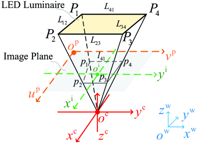
The system diagram is illustrated in Fig. 1. Four coordinate systems are utilized for localization, which are the pixel coordinate system (PCS) on the image plane222As shown in Fig. 1, the image plane is a virtual plane. In this paper, the camera is a standard pinhole camera. The actual image plane is behind the camera optical center (i.e., the pinhole), . To show the geometric relations more clearly, the virtual image plane is set up in front of as done in many papers [26, 27]. In particular, the virtual image plane and the actual image plane are centrally symmetric, and is the center of symmetry., the image coordinate system (ICS) on the image plane, the camera coordinate system (CCS) and the world coordinate system (WCS) . In PCS, ICS and CCS, the axes , and are parallel to each other and, similarly, , and are also parallel to each other. Additionally, is at the upper left corner of the image plane and is at the center of the image plane. Moreover, is termed as the principal point, whose pixel coordinate is . In contrast, is termed as the camera optical center. Furthermore, and are on the optical axis. The distance between and is the focal length , and thus the -coordinate of the image plane in CCS is .
A VLC-enabled rectangular LED luminaire is constructed by four vertices () mounted on the ceiling. The four 3D reference lines () are the edges of the luminaire. In addition, is the world coordinate of the th vertex of the luminaire, which is assumed to be known at the transmitter and can be transmitted by VLC as the time-domain information [4, 3]. Moreover, the unit normal vector of the luminaire in WCS, , can be calculated by the world coordinates of the luminaire’s vertices.
On the other hand, the receiver is a standard pinhole camera which is not coplanar with the luminaire. Therefore, the transmitter and the receiver produced a rectangular pyramid which contains many space-domain information. In the rectangular pyramid , the rectangle is called the base face. Meanwhile, we define as the lateral face determined by the vertices , () and . In addition, is the th vertex and is called the apex. In the camera, is the projection of on the image plane. Moreover, is the 2D projection on the image plane of . Note that many existing PnL algorithms assume that the 3D-2D correspondences are known in advance, which is too ideal in practice [8]. In contrast, in this work, the 3D-2D correspondences are unknown. To estimate the pose and position of the receiver without the 3D-2D correspondences, the camera is used to simultaneously capture the time- and space-domain information.
The pixel coordinate of is denoted by , and this coordinate can be obtained by the camera through image processing [17]. Based on the single-view geometry theory, the image coordinate of , , can be obtained as follows:
| (1) |
where and are the physical size of each pixel in the and directions on the image plane, respectively. The camera’s intrinsic parameters, including and the focal ratio and , can be calibrated in advance [13]. The transformation from CCS to WCS can be expressed as follows [22]:
| (2) |
where and are the world and camera coordinates of the same object, respectively. In addition, and denote the pose and the position of the camera in WCS, respectively. The task of the localization is to find out and .
III Calculating The Luminaire Information In CCS
In this section, the information of the luminaire in CCS, including its normal vector and its vertices’ coordinates , , is calculated based on the space-domain information in two steps. In the first step, is estimated based on the plane and solid geometry theory. Then, based on , , are estimated by the solid geometry theory.
III-A The Normal Vector Of The Luminaire In CCS
In ICS, the point-normal form equation of a given can be expressed as [25]:
| (3) |
where is the image coordinate of a point on which can be obtained by the single-view geometry theory , is the rotate angle from -axis to in anticlockwise direction, and is the distance from to . Since and are on , and can be obtained based on the image coordinates of and . From (2), there are two points whose image coordinates are and are on . Since the two points are also on the image plane, their camera coordinates are and . Since the two points and are on , we can represent in CCS in the general form as:
| (4) |
where , and .
In CCS, the general form equation of the rectangle can be expressed as:
| (5) |
where , and are unknown constants. From (5), the normal vector of the rectangle can be expressed by . In CCS, let () denotes the normal vector of and () denotes the direction vector of . Since is the intersection line of the rectangle and , can be calculated as . Based on the solid geometry, we have:
| (6) |
Define and , and we can obtain and as the functions of , and by solving (6). Therefore, the normalized normal vector of the rectangle (i.e., the orientation of the luminaire) in CCS can be expressed as:
| (7) |
where:
| (8) |
III-B Camera Coordinates Of The Luminaire’s Vertices
Since is the intersection point of the rectangle , and , its camera coordinate can be calculated as , where:
| (9) |
The other three () can be calculated in the similar method of (9). In general, the camera coordinate () can be calculated as follows:
| (10) |
From (10), we can observe that can be represented according to . Next, we will calculate based on the solid geometry.
The volume of the rectangular pyramid can be calculates as , where is the area of the luminaire and is known in advance. Additionally, is the distance from to the rectangle . For the triangular pyramid , its volume can be calculated as follows:
| (11) |
where . Substituting (10) into (11), we have , where , where . The volumes of the other three triangular pyramid , and , denoted by , and , respectively, can be obtained in the same way. Since , can be calculated as follows:
| (12) |
IV The Basic Algorithm of V-P4L
In this section, the basic algorithm of V-P4L is proposed for scenarios where LEDs have the same height. The basic algorithm of V-P4L contains three steps. In the first step, based on the orientation information of the luminaire estimated in Section III, the rotation angles corresponding to the axis and axis can be obtained by the single-view geometry theory. Then, based on the LLS method and the single-view geometry theory, the basic algorithm of V-P4L can properly match the 3D-2D correspondences, and obtain the rotation angles corresponding to the axis and the 2D coordinate of the camera. Finally, based on the single-view geometry theory, V-P4L can estimate the -coordinate of the camera.
IV-A Calculate the rotation angles corresponding to the axis and axis
Let , and denote the rotation matrices of WCS along the axis, axis and axis, respectively. Given , and as follows [28]:
| (13) |
| (14) |
and
| (15) |
where , and are the unknown Euler angles corresponding to the axis, axis and axis, respectively, the rotation matrix from CCS to WCS can be given as [28]:
| (16) |
In this section, the basic algorithm of V-P4L is proposed for scenarios where LEDs have the same height. Therefore, the normal vector of the luminaire can be denoted by . Based on the single-view geometry theory, the relationship between and can be given as [22]:
| (17) |
Therefore, we have:
| (18) |
The estimated rotation angles and can be obtained by solving (18).
IV-B Calculate the rotation angles corresponding to the axis and the 2D coordinate of the camera
Based on the single-view geometry theory, the relationship between () and can be given as [22]:
| (19) |
where is known in advance and can be obtained by the camera as the time-domain information. In addition, is the space-domain information that is estimated in Subsection III-B. Moreover, is the 3D world coordinate of the camera. In (19), there are four unknown parameters , , and . If the 3D-2D correspondences are known in advance, we can easily obtain the four unknown parameters with the four vertices’ world and camera coordinates. However, as analyzed in Section I, the 3D-2D correspondences are unknown for practical considerations. In this paper, we can calculate these parameters based on the LEDs’ information in both time and space domains. For mathematical analysis, we define:
| (20) |
and thus we can rewrite (19) as follows:
| (21) |
The three unknown parameters , and in (21) can be calculated by the LLS estimator, which can be expressed in a matrix form as follows:
| (22) |
where and (), where:
| (23) |
| (24) |
and
| (25) |
Therefore, the unknown parameters can be given by:
| (26) |
where is the estimate of .
Since the 3D-2D correspondences are not known in advance, given a certain and (), we cannot obtain their exact correspondence relationship. Fortunately, there are four () and (), and that means there are only different and (). Therefore, for each (, ), we can obtain 6 candidate solutions corresponding to 6 (), and one of which is , where represents the exact corresponding to . Therefore, we can obtain total 36 solutions which can further be separated into 6 groups according to 6 different . To obtain a reasonable solution, here we propose a strategy that estimates by averaging the 6 closest solutions (i.e., 6 ) in the 6 groups of solutions, which can be expressed as follows:
| (27) |
This strategy will be verified in simulations. In this way, based on the information in both time and space domains, the basic algorithm of V-P4L can properly match the 3D-2D correspondences, and obtain the rotation angles corresponding to the axis and the 2D coordinate of the camera .
IV-C Calculate the -coordinate of the camera
In Subsection IV-B, we have obtained and . In (21), there is still one unknown parameter . In this section, the basic algorithm of V-P4L is proposed for scenarios where LEDs have the same height, i.e., . Based on the single-view geometry theory, we can obtain the relationship between and from (21) as:
| (28) |
The estimated -coordinate of the camera in WCS can be calculated as follows:
| (29) |
where is the estimate of .
In this way, the estimated pose and position of the camera can be obtained without the ideal 2D-3D correspondence assumption.
V The Correction algorithm of V-P4L
Most of existing studies including the basic algorithm of V-P4L proposed in Subsection IV assume that LEDs have the same height [14, 15]. However, this may not always be true in practice. For instance, ceilings may be tilted due to the imperfect decoration or deliberate design. In these scenarios, the localization accuracy can be significantly degraded. Therefore, in this subsection, based on the basic algorithm of V-P4L, we propose a correction algorithm of V-P4L for the scenarios where LEDs have different heights, V-P4L-DH. Based on the single-view geometry theory and the LLS method, V-P4L-DH can properly match the 3D-2D correspondences and obtain the 2D position of the camera. Based on the 2D localization, V-P4L-DH can achieve 3D localization by a simple optimization method.
V-A 2D Localization
For 2D-localization case where the -coordinate of the camera is known in advance, based on the single-view geometry theory, (28) can be rewritten as follows:
| (30) |
where . Since the 3D-2D correspondence are not known in advance, given a certain and , we do not know their correspondence relationship. Fortunately, there are four and , and thus we can estimate using the same LLS method of solving (26). Then, from (20), we have:
| (31) |
where is the estimate of . The estimated rotation angles corresponding to the axis and axis can be obtained by solving (31). Then, the pose of the camera and 2D position of the camera can be obtained according to (20)(27), where and are the estimated and -coordinates of the camera, respectively.
V-B 3D Localization
For 3D-localization case, the -coordinate of the camera is not known in advance. For indoor scenario, the range of must be , where is the maximum height of the room. Based on the above 2D-localizatoin algorithm, for different , we can obtain different and . Based on the estimated normal vector of the luminaire in CCS , we have [22]:
| (32) |
where denotes the estimated normal vector of the luminaire in WCS when the -coordinate of the camera is . Since the world coordinates of the luminaire’s vertices () are known in advance, the actual normal vector of the luminaire in WCS can be calculated as follows:
| (33) |
where . Therefore, the difference between the estimated and actual normal vectors of the luminaire in WCS can be given as:
| (34) |
The estimated -coordinate of the camera can be obtained by the minimum , i.e.:
| (35) |
To reduce the complexity of V-P4L-DH, we propose a -step segmentation optimization strategy for V-P4L-DH. In the first step, we divide the range of into segments evenly, and set:
| (36) |
i.e., we set the interval between adjacent as . Substituting all the into (34), we have . According to (35), we can find the minimal . We denote the minimal by where is the index of the that corresponding to . In the second step, we reduce the range of to . We set:
| (37) |
i.e., the interval between adjacent is , where . We repeat the process of the first step for the second step to the th step until we can obtain the precise according to (35), and obtain the optimal and . Therefore, based on the simple optimization method, we can obtain the pose and 3D position of the receiver when LEDs have different heights.
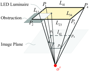
In this way, when LEDs have the same height, the basic algorithm of V-P4L can be implemented for high accuracy at low complexity. When LEDs have different heights, V-P4L-DH can be implemented for high accuracy. In summary, V-P4L algorithm is elaborated in Algorithm 1. Although V-P4L requires the LED luminaire to be a rectangle, it is robust to partial occlusion, which is meaningful due to the limitation on the camera’s field of view. For instance, if the projection of , , is blocked by barriers and not on the image plane as shown in Fig. 2, the pixel coordinate of can be determined by the intersection of and , and thus V-P4L can be still successively implemented.
Input:
();
();
, , , , and .
Output: and .
VI SIMULATION RESULTS AND ANALYSES
| Parameter | Value | |
|---|---|---|
| Room size () | ||
| Length and width of LED luminaire | Length | Width |
| LED semi-angle, | ||
| Principal point of camera | ||
| Focal ratio of camera | ||
| The distance between the PD and the camera in eCA-RSSR, | ||
Since V-P4L combines VLC and computer vision based localization, a VLP algorithm named enhanced camera assisted received signal strength ratio algorithm (eCA-RSSR) [14], and a typical computer vision algorithm termed P4L algorithm [25] are conducted as the baselines schemes in this section.
VI-A Simulation Setup
The system parameters are listed in Table II. The LED luminaire is deployed in the center of the ceiling. The length of the luminaire which is along the -axis is set to [10, 29], and the widths of luminaire which is along the -axis are varied according to configurations. We set the rectangular luminaire tilt with various angles along the -axis to represent that LEDs have different heights. All statistical results are averaged over independent runs. For each simulation run, the receiver positions are selected in the room randomly. The pinhole camera is calibrated. The image noise is modeled as a white Gaussian noise having an expectation of zero and a standard deviation of [30]. Since the image noise affects the pixel coordinate of the luminaire’s projection on the image plane, the pixel coordinate is obtained by processing 20 images for the same position. Moreover, we use two-step segmentation optimization strategy, and we set and .
Note that since eCA-RSSR requires three LEDs for localization, we assume that the four LEDs at the vertices of the luminaire are used for eCA-RSSR and we choose the three LEDs with the highest RSSs to achieve best performance for eCA-RSSR. Additionally, all the LEDs transmit different information in eCA-RSSR, which is not required in V-P4L and the P4L algorithm. Therefore, compared with V-P4L, the VLC link of eCA-RSSR is more complex. Furthermore, eCA-RSSR relies on the perfect Lambertian pattern model. However, the VLC channel model can be quiet different from the Lambertian pattern model even using the LED having nearly-ideal Lambertian pattern, as shown in [19], and the difference can be over 100% in certain cases. Therefore, we set a random deviation for the Lambertian pattern model for eCA-RSSR, conservatively. On the other hand, the P4L algorithm exploits a rectangle to estimate the position and pose of the camera. The P4L algorithm assumes that the camera knows the 3D-2D correspondences. However, the beacon in the P4L algorithm cannot convey time-domain information to the camera, which make the assumption impractical. In addition, the method to find the 3D-2D line correspondences given by [8] is also not practical when the camera captures the beacons on the ceiling as stated in Section I. Therefore, we set a random error rate for the 3D-2D correspondences, conservatively. Moreover, the P4L algorithm can only obtain the relative position. For comparison with V-P4L, we transform the relative position into the absolute position for the P4L algorithm in this section.
We evaluate the performance of V-P4L in terms of its accuracy of position and pose estimation. We define position error as:
| (38) |
where and are the actual and estimated world coordinates of the receiver, respectively. Additionally, the accuracy of pose estimation can be measured by the orientation error which is defined as:
| (39) |
where and are the actual and estimated rotation angles, respectively.
In this section, we will evaluate the performance of V-P4L under various tilted angles of the luminaire, various widths of the luminaire and various image noise. We compare for both scenarios where LEDs have the same height and have different heights, which are denoted by SH and DH, respectively in the figures. Since the basic algorithm of V-P4L is used when LEDs have the same height, we denote the basic algorithm of V-P4L by V-P4L-SH in figures.
VI-B Effect Of Luminaire’s Tilted Angle On Accuracy Performance
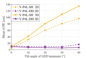
We first evaluate the effect of the tilted angles of the luminaire on localization accuracy of V-P4L for both 2D and 3D localization. This performance is represented by the means of PEs with the tilted angles of the luminaire varying from to . The width of the luminaire is . As shown in Fig. 3(a), for 2D localization, when the tilted angle of the luminaire is , i.e., LEDs have the same height, the basic algorithm of V-P4L can obtain a slight better performance than V-P4L-DH. However, as the tilted angle of the luminaire varying from to , the means of PEs of the basic algorithm of V-P4L increase from about 5 cm to about 98 cm. For 3D localization, the means of PE of the basic algorithm of V-P4L increase from about 10 cm to about 135 cm. In contrast, for all the tilted angles of the luminaire, the means of PEs of V-P4L-DH are less than 18 cm for both 2D and 3D localization. Since in 3D localization the estimated 2D position and pose is optimized meanwhile when search for the optimal , V-P4L can achieve better performance for 3D localization than 2D localization.
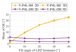
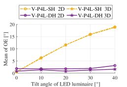
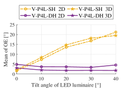
Since the accuracy of pose estimation is also affected by the tilted angle of the luminaire, we then evaluated the effect of the tilted angles on OEs of V-P4L for both 2D and 3D localization. As shown in Fig. 4, the OEs along the -axis, -axis and -axis are shown seperately. When the tilted angle of the luminaire is , the basic algorithm of V-P4L can obtain slight better performance than V-P4L-DH. However, as the tilted angle of the luminaire varying from to , the means of OEs of the basic algorithm of V-P4L increase from about to about . In contrast, for all the tilted angles of the luminaire, V-P4L-DH can achieve consistent well performance, and the means of OEs are always less than .
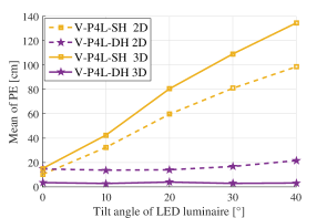
We also evaluate the effect of partial occlusion as shown in Fig. 2 on localization accuracy of V-P4L. Figure 3(a) shows the accuracy performance of position estimation when there is no occlusion in the scenario. In contrast, Fig. 3(b) shows the accuracy performance of position estimation when is blocked and is not on the image plane. As shown in Fig. 3(b), when the luminaire is partially blocked, V-P4L can still achieve high accuracy. In particular, the accuracy performance of the basic algorithm of V-P4L is almost the same in Fig. 3(a) and Fig. 3(b). In addition, for V-P4L-DH, the 2D-localization accuracy reduces about 2 cm, while the 3D-localization accuracy improves about 4 cm. Therefore, V-P4L is robust to partial occlusion as introduced in Section V.
In this subsection, we have verified V-P4L can achieve high accuracy for both 2D and 3D localization. Since 2D localization is the special case of 3D localization where the height of the receiver is known in advance, in the following subsections, we will only show the simulation results for 3D localization.
VI-C Effect Of Luminaire’s Widths On Accuracy Performance
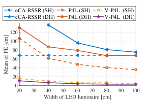
We then evaluate the effect of the luminaire’s width on localization accuracy of V-P4L. This performance is represented by the means of PEs with the width varying from to . For the scenarios where LEDs have different heights, the tilted angle of the luminaire is . As shown in Fig. 5, for both the scenarios where LEDs have the same height and have different heights, V-P4L is able to obtain the best performance among the three algorithms. When LEDs have the same height, the means of PEs of the basic algorithm of V-P4L are below . In contrast, for eCA-RSSR, the means of PEs are around 70 cm as the width of the luminaire increases from to . Additionally, for the P4L algorithm, the means of PEs decrease from over to about . On the other hand, when LEDs have different heights, the means of PEs of V-P4L-DH decrease from about 10 cm to 5 cm. In contrast, the means of PEs of both eCA-RSSR and the P4L algorithm are higher than 50 cm for all the widths of the luminaire. As shown in Fig. 5, the localization accuracy increases with the increase of the width for V-P4L. However, the PEs of V-P4L are always less than regardless of the height differences among LEDs using a single LED luminaire whose width is longer than , and thus V-P4L can be applied to popular indoor luminaires.
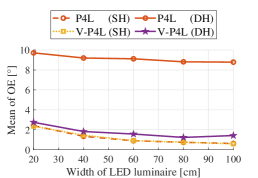
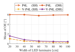
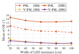
Since the accuracy of pose estimation is also affected by the width of the LED luminaire, we then compare the OEs between V-P4L and the P4L algorithm with varying widths of the luminaire. As shown in Fig. 6, for V-P4L, all the means of OEs along the -axis, -axis and -axis are less than regardless of the height differences among the LEDs. When LEDs have the same height, the means of OEs along the -axis and -axis decrease from about to about and from to about , respectively for both the basic algorithm of V-P4L and the P4L algorithm. Additionally, the means of OEs of the basic algorithm of V-P4L along the -axis decrease from about to about , which is over better than that of the P4L algorithm. On the other hand, when LEDs have different heights, for V-P4L-DH, the means of OEs along the -axis, -axis and -axis decrease from to , from to and from to , respectively. In contrast, for the P4L algorithm, the means of OEs along the -axis, -axis and -axis are about , , , respectively. Therefore, compared with the P4L algorithm, V-P4L can obtain higher accuracy for pose estimation using popular indoor luminaire.
VI-D Effect Of Image Noise On Accuracy Performance
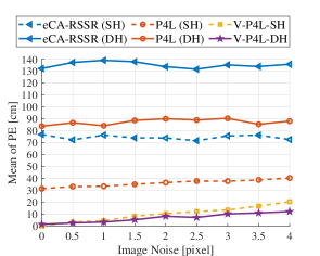
In this subsection, we evaluate the effect of the image noise on the localization performance of V-P4L when the width of the luminaire is . When LEDs have different heights, the tilted angle of the luminaire is . The image noise is modeled as a white Gaussian noise having an expectation of zero and a standard deviation, , ranging from to [30]. Figure 7 shows the means of PEs versus image noises. As shown in Fig. 7, when LEDs have the same height, the means of PEs of the basic algorithm of V-P4L increase from to as the image noise increases from to . In contrast, for the P4L algorithm, the means of PEs increase from 30 cm to 40 cm. Additionally, for eCA-RSSR, the means of PEs are around 75 cm. When LEDs have different heights, the means of PEs of V-P4L-DH increase from 0 cm to 11 cm. In contrast, for the P4L algorithm, the means of PEs are about 85 cm. Additionally, for eCA-RSSR, the means of PEs are about 135 cm. Therefore, compared with the P4L algorithm and eCA-RSSR, V-P4L can obtain higher accuracy for position estimation.
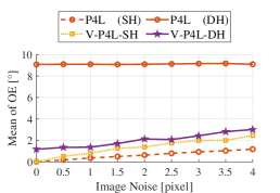
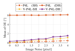
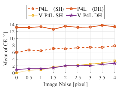
Finally, we compare the accuracy of pose estimation between V-P4L and the P4L algorithm under different image noises. Figure 8 show the means of orientation errors along -axis, -axis and -axis with the image noise ranging from to . When LEDs have the same height, the means of OEs of the basic algorithm of V-P4L along -axis, -axis and -axis increase from to , from to and from to , respectively. In contrast, for the P4L algorithm, the means of OEs along the -axis and -axis increase from to and from to , respectively, which is slight better than the basic algorithm of V-P4L. However, the means of OEs of the P4L algorithm along the -axis increase from about to about which is over worse than that of the basic algorithm of V-P4L. On the other hand, when LEDs have different heights, for V-P4L-DH, the means of OEs along -axis, -axis and -axis increase from about to less than . In contrast, for the P4L algorithm, the means of OEs along -axis, -axis and -axis are about , , , respectively. Therefore, compared with the P4L algorithm, V-P4L can obtain more stable and accurate pose estimation regardless of the image noise.
VII CONCLUSION
We have proposed a novel indoor localization algorithm named V-P4L that estimates the position and pose of the camera using a single, VLC-enabled LED luminaire. The camera is used to simultaneously capture the information in both time and space domains. Based on the information captured by the camera, V-P4L does not require the 3D-2D correspondences. Moreover, V-P4L can be implemented regardless of the height differences among LEDs. Therefore, V-P4L can achieve higher feasibility and higher accuracy than eCA-RSSR and the conventional PnL algorithms. Simulation results have shown that for V-P4L the position error is always less than and the orientation error is always less than using popular indoor luminaires. In the future, we will experimentally implement V-P4L based on a dedicated test bed.
References
- [1] P. Pathak, X. Feng, P. Hu, and P. Mohapatra, “Visible light communication, networking and sensing: Potential and challenges,” IEEE Commun. Surveys Tuts., vol. 17, no. 4, pp. 2047–2077, 4th Quart. 2015.
- [2] J. Lim, “Ubiquitous 3D positioning systems by LED-based visible light communications,” IEEE Wireless Commun., vol. 22, no. 2, pp. 80–85, Apr. 2015.
- [3] Y. Yang, Z. Zeng, J. Cheng, C. Guo, and C. Feng, “A relay-assisted OFDM system for VLC uplink transmission,” IEEE Trans. Commun., vol. 67, no. 9, pp. 6268–6281, Sept. 2019.
- [4] Y. Yang, Z. Zeng, J. Cheng, and C. Guo, “An enhanced DCO-OFDM scheme for dimming control in visible light communication systems,” IEEE Photon. J., vol. 8, no. 3, pp. 1–13, Jun. 2016.
- [5] N. Piasco, D. Sidibé, C. Demonceaux, and V. Gouet-Brunet, “A survey on visual-based localization: On the benefit of heterogeneous data,” Pattern Recognition, vol. 74, pp. 90–109, Sep. 2018.
- [6] A. Ben-Afia, L. Deambrogio, D. Salós, A.-C. Escher, C. Macabiau, L. Soulier, and V. Gay-Bellile, “Review and classification of vision-based localisation techniques in unknown environments,” IET Radar, Sonar & Navigation, vol. 8, no. 9, pp. 1059–1072, Aug. 2014.
- [7] T.-H. Do and M. Yoo, “An in-depth survey of visible light communication based positioning systems,” Sensors, vol. 16, no. 5, pp. 678, May 2016.
- [8] T. Goto, S. Pathak, Y. Ji, H. Fujii, A. Yamashita, and H. Asama, “Line-based global localization of a spherical camera in manhattan worlds,” in 2018 IEEE Int. Conf. Robotics Automation (ICRA), 2018, pp. 2296–2303.
- [9] C. Sertthin, T. Ohtsuki, and M. Nakagawa, “6-axis sensor assisted low complexity high accuracy-visible light communication based indoor positioning system,” IEICE Trans. Commun., vol. 93, no. 11, pp. 2879–2891, Nov. 2010.
- [10] K. Qiu, F. Zhang, and L. Ming, “Let the light guide us: VLC-based localization,” IEEE Robot. Autom. Mag., vol. 23, no. 4, pp. 174–183, Dec. 2016.
- [11] T. Q. Wang, Y. A. Sekercioglu, A. Neild, and J. Armstrong, “Position accuracy of time-of-arrival based ranging using visible light with application in indoor localization systems,” J. Lightw. Technol., vol. 31, no. 20, pp. 3302–3308, Oct. 2013.
- [12] B. Zhu, J. Cheng, Y. Wang, J. Yan, and J. Wang, “Three-dimensional VLC positioning based on angle difference of arrival with arbitrary tilting angle of receiver,” IEEE J. Sel. Areas Commun., vol. 36, no. 1, pp. 8–22, Jan. 2018.
- [13] L. Bai, Y. Yang, C. Guo, C. Feng, and X. Xu, “Camera assisted received signal strength ratio algorithm for indoor visible light positioning,” IEEE Commun. Lett., vol. 23, no. 11, pp. 2022–2025, Nov. 2019.
- [14] L. Bai, Y. Yang, C. Feng, and C. Guo, “An enhanced camera assisted received signal strength ratio algorithm for indoor visible light positioning,” in Proc. IEEE Int. Conf. Commun. Workshops (ICC Wkshps), 2020, pp. 1–6.
- [15] L. Li, P. Hu, C. Peng, G. Shen, and F. Zhao, “Epsilon: A visible light based positioning system,” in Proc. 11th USENIX Symp. Netw. Syst. Design Implement (NSDI’14), 2014, vol. 14, pp. 331–343.
- [16] M. Yasir, S.-W. Ho, and B. N. Vellambi, “Indoor position tracking using multiple optical receivers,” J. Lightw. Technol., vol. 34, no. 4, pp. 1166–1176, Feb. 2015.
- [17] Y. Li, Z. Ghassemlooy, X. Tang, B. Lin, and Y. Zhang, “A VLC smartphone camera based indoor positioning system,” IEEE Photon. Technol. Lett., vol. 30, no. 13, pp. 1171–1174, Jul. 2018.
- [18] A.M. Vegni and M. Biagi, “An indoor localization algorithm in a small-cell led-based lighting system,” in Proc. IEEE Int. Conf. Indoor Position. Indoor Navig. (IPIN), 2012, pp. 1–7.
- [19] F. Miramirkhani and M. Uysal, “Channel modeling and characterization for visible light communications,” IEEE Photonics J., vol. 7, no. 6, pp. 1–16, Dec. 2015.
- [20] Z. Dong, T. Shang, Y. Gao, and Q. Li, “Study on VLC channel modeling under random shadowing,” IEEE Photonics J., vol. 9, no. 6, pp. 1–16, Dec. 2017.
- [21] A. Cailean and M. Dimian, “Current challenges for visible light communications usage in vehicle applications: A survey,” IEEE Commun. Surveys Tuts., vol. 19, no. 4, pp. 2681–2703, 4th Quart. 2017.
- [22] C. Xu, L. Zhang, L. Cheng, and R. Koch, “Pose estimation from line correspondences: A complete analysis and a series of solutions,” IEEE Trans. Pattern Anal. Mach. Intell., vol. 39, no. 6, pp. 1209–1222, Jun. 2017.
- [23] B. Přibyl, P. Zemčík, and M. Čadík, “Absolute pose estimation from line correspondences using direct linear transformation,” Comput. Vis. Image Und., vol. 161, pp. 130–144, Aug. 2017.
- [24] Alexander V., Jan F., and Francesc M.-N., “Accurate and linear time pose estimation from points and lines,” in Europ. Conf. Comp. Visi. (ECCV), 2016, pp. 583–599.
- [25] Wang X., Pan S., Qiu L., S L., and Song Z., “Analytic algorithm of pose estimation based on two pairs of parallel lines,” Chin. J. Sci. Instrum., vol. 29, no. 3, pp. 600, Oct. 2008.
- [26] A. Masselli and A. Zell, “A new geometric approach for faster solving the perspective-three-point problem,” in Proc. 22nd Int. Conf. Pattern Recognit. (ICPR), 2014, pp. 2119–2124.
- [27] L. Kneip, D. Scaramuzza, and R. Siegwart, “A novel parametrization of the perspective-three-point problem for a direct computation of absolute camera position and orientation,” in Proc. 24th IEEE Conf. Comput. Vis. and Pattern Recognit. (CVPR), 2011, pp. 2969–2976.
- [28] Arthur M. L., “On the calculation of Euler angles from a rotation matrix,” IEEE Trans. on Commun., vol. 17, no. 3, pp. 335–337, Aug. 1986.
- [29] Philips, “LED-tubes,” http://www.lighting.philips.com.cn/prof/led-lamps-and-systems/led-tubes#pfpath=0-LED_GR, 2020, [Online, accessed 8-Apr.-2020].
- [30] L. Zhou, Y. Yang, M. Abello, and M. Kaess, “A robust and efficient algorithm for the pnl problem using algebraic distance to approximate the reprojection distance,” in Proc. AAAI Conf. Artif. Intell., 2019, vol. 33, pp. 9307–9315.