Scientific instrument for creation of effective
Cooper pair mass spectroscopy
Abstract
We describe electronic instruments for creation of effective Cooper pair spectroscopy. The suggested spectroscopy requires study of electric field effects on the surface of cleaved superconductors. The electronic instrument reacquires low noise amplifier with 106 amplitude amplification which we have formerly used for study of Johnson-Nyquist and Schottky noises. The nonspecific amplifier is followed by high-Q tunable resonance filter based on schematics of general impedance converter topology which is also and innovative device. The work of the device is based on the Manhattan equation of operational amplifier. After a final nonspecific amplification the total amplification can exceed 109 and in such a way sub-nano-volt signals can be reliably detected. In short the observation of new effects in condensed matter physics leads to creation of new generation of electronic equipment.
1 Introduction
Effective masses of charge carriers are important notions of the physics of condensed matter. In the physics of metals and semiconductors they represents basic electronic phenomena related to thermodynamics and transport properties. Alas the physics of superconductivity is an exception. Except for some episodic hints, effective masses of super-fluid charge carriers have never been systematically determined. The purpose of the present study is to evaluate experimental efforts necessary for the creation of Cooper pair mass spectroscopy: equipment, samples, consumptives, and perspectives for further development. A review of present status of the problem together with detailed theory is given in our recent papers [1, 2] and references therein ([3, 4, 5, 6, 7, 8, 9, 10, 11, 12, 13, 14, 15, 16] and so on). In the next Sec. 2 we recall the main theoretical results, then we describe the suggested set-ups in Sec. 3. In the Sec. 4 we describe the electronic equipment which has to be build. Later on in Sec. 5 we describe the necessary samples and the experimental data processing for the planned first successful experiments.
2 Theory Review
In this section we recall only the final theoretical formulae which have to be used for the creation of Cooper pair mass spectroscopy.
2.1 Current induced contact potential difference
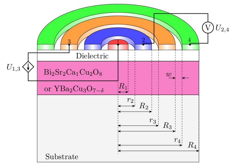
The initial idea for creation of Cooper pair mass spectroscopy is to use current induced contact potential difference or Bernoulli effect in superconductors. For the detailed list of references, physics and history of the problem see our recent article [1]. We suppose capacitive coupling of the cleaved superconductor by 4 electrodes. Between electrodes (1) and (3) is applied driving voltage, which is a sum of two sinusoidal: one basic with frequency high and another one modulated with much smaller frequency
| (1) |
Then between those probes (1) and (3) a current flows
| (2) | |||
| (3) |
where and are the capacitances between the electrodes and the superconductor samples.
This electrostatically driven current in thin superconducting film with thickness much smaller than penetration depth creates the Bernoulli voltage
where the high frequency terms with frequencies are not written. The purpose of the experiment is to use the voltage amplitude of the demodulated signal with frequency . The ratio
| (4) |
of the experimentally measurable amplitudes determines the effective mass of Cooper pairs
| (5) |
where we suppose that the second electrode is a ring internal and external radii and . The geometry is described in the next section.
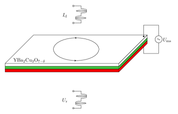
2.2 Electrostatically modulated thin film kinetic inductance
Historically, the first experimental determination of effective mass of Cooper pairs has been performed [17, 18] using the formula [19]
| (6) |
where is the temperature dependent kinetic inductance per square sample, analogously to ts extrapolated to zero temperature value, is the change of the kinetic inductance under the electrostatic modulation by extra electric charge per unit area , i.e. the electrostatic induction
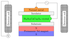
2.3 Electric field induced surface magnetization of the vortex phase
Last possibility for creation of Cooper pair mass spectroscopy is to study sinusoidal modulation of the excess surface magnetization per unit area under the modulation of surface charge density
| (7) |
where is the external magnetic field which is perpendicular to the superconductor surface of extreme type-II superconductor which are, for example, all high- cuprates.
3 Experimental Set-ups
Here we describe the set-ups for the experiments, which theory we review in the former section. The set-ups corresponding to the described 3 methods are depicted in Figs. 1, 2 and 3
After this brief description of the theory and set-ups in the next section we will focus on the electronic necessary to be build for the suggested Cooper pair mass spectroscopy.
4 Electronics of the instrument for Cooper pair mass spectroscopy
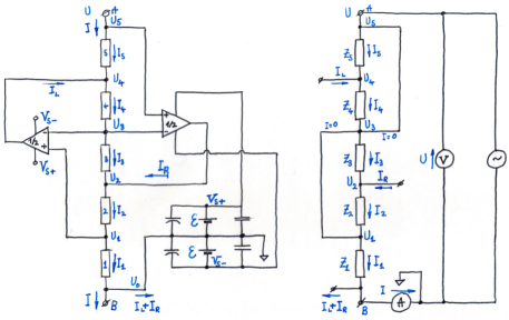
All considered in the former section experiments require measurement of nano-volt range signals which is below the standard electronics equipment and requires development on unique electronics. For example the block-scheme for observation of current induced CPD is schematically represented in Fig. 4.

The symbolically denoted there voltmeter starts with a pre-amplifier shown in Fig. 5.
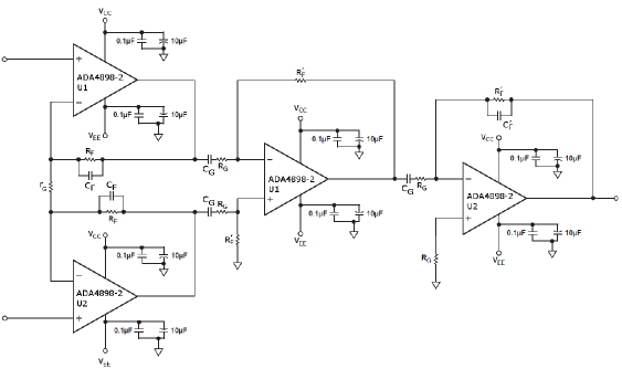
This pre-amplifier is reliable and we used it for education experiments for determination of the Boltzmann constant [21] and the electron charge [23]. The device is so robust that we reproduced in more than 300 samples for the set-ups of 5-th and 6-th high-school Experimental physics olympiads [22, 24]. The pre-amplifier consists of a buffer with a double operational amplifiers. The buffer has a frequency dependence of the amplification as for a non-inverting amplifier . After the buffer we have a difference amplifier with frequency dependence of the amplification coinciding with the last inverting amplifier . In such a way the total amplification is given by the product
| (8) |
The offset voltages of the operational amplifiers are stopped by the large capacitors followed by large gain resistors . In such a way for relatively low frequencies for which nevertheless the amplification is approximately constant
which can be clearly seen at the frequency dependence of the frequency calculated according to our formulae [21]
| (9) | |||
and shown in Fig. 8.
For this study we re-derived the Manhattan equation of OpAmps [25], applied it in the theory of amplifiers [26], and studied statistical properties of the crossover frequency of the crossover frequency of the used low-noise OpAmp ADA4898-2 [27].
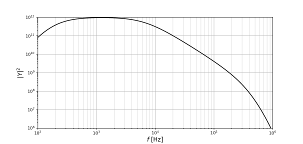
Concerning the nonspecific amplifier, we have reached saturation using one of the best low-noise OpAmp after 106 amplification the signal is slightly below the overload regime. In order to go further for observation of new physical effects we need to construct a new type resonance filter having Q-factor comparable with quartz resonator but having advantage to be tunable. We have solved this long standing endeavor using the topology of general impedance converter (GIC) [28] drawn in Fig. 7.
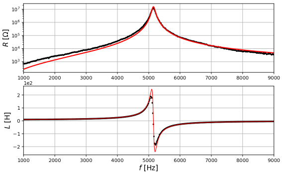
The general theoretical formula we have derived ()
| (10) |
perfectly match the experimental data depicted in Fig. 8.
The detailed description of the resonator will be published elsewhere [29]. Now we can describe in short the planned experiment.
5 Experiment
All details of the planned experiment are already tested from the fundamental theory of a new effect in superconductors. The last missing ling of the chain was the resonator by GIC and now we can start creation of the scientific instrument for the new Cooper pair mass spectroscopy. In order to alleviate the success in the initial stage we recommend the use of 90 K Bi2Sr2Ca1Cu2O8 mono-crystal which can be easily cleaved. In conclusion we believe that within one year we will have first intentionally done experiment for determination of in high- cuprates.
Acknowledgments
The authors thank for correspondence, suggestion and interest to the present project to Dmitri Basov, Hassan Chamati, Mauro Doria, Stefan Drechsler, Vadim Grinenko, Alexei Koshelev, Milorad Milosevic, Nikolay Plakida, Herman Suderow, Thomas Timusk, and Nikolay Tonchev. The authors appreciate the friendly atmosphere of the school. After presenting our idea for measurements of surface magnetization during the discussion sections and afterwards, we learned a lot about molecular magnets from Miroslav Georgiev, where similarly to the physics of superconductivity, the magnetic field plays an essential role [30, 31, 32, 33, 34]. Continuous efforts of Hassan Chamati ensured high level “bio-field” and scientific level. One of the authors, AMV acknowledges the support by National program “Young scientists and postdoctoral researchers” approved by DCM 577, 17.08.2018.
References
References
- [1] Mishonov T M and Varonov A M 2020 Physica C: Superconductivity and its Applications 577 1353712
- [2] Mishonov T M, Danchev V I and Varonov A M 2020 Phys. Scr. 95
- [3] London F and London H 1935 Proc. R. Soc. London, Ser. A 149 71–88
- [4] Gorter C J 1949 Il Nuovo Cimento Series 9 6 245–250
- [5] Onsager L 1949 Suppl. al Il Nuovo Cimento Series 9 6 249
- [6] Ginzburg V L and Landau L D 1950 Zh. Eksp. Teor. Fiz. 20 1064–1082
- [7] London F 1950 Superfluids (New York: Wiley)
- [8] Lifshitz I M, Azbel Y M and Kaganov M I 1973 Electron theory of metals (New York: Consultants bureau)
- [9] Landau L D and Lifshitz E M 1980 Statistical Physics. Part 2 (Course of theoretical physics vol 9) (New York: Pergamon)
- [10] Landau L D and Lifshitz E M 1988 Fluid Mechanics (Course of theoretical physics vol 6) (New York: Pergamon)
- [11] Lifshitz E M and Pitaevskii L P 1980 Physical Kinetics (Course of theoretical physics vol 10) (New York: Pergamon)
- [12] Abrikosov A A 1988 Fundamentals of the Theory of Metals (Amsterdam: North Holland)
- [13] Cabrera B and Peskin M E 1989 Physical Review B 39 6425–6430
- [14] Mishonov T M 1994 Phys. Rev. B 50 4009–4014
- [15] Basov N D and Timusk T 2005 Rev. Mod. Phys. 77 721–729
- [16] Plakida N 2010 High-Temperature Cuprate Superconductors (New York: Springer)
- [17] Fiory A T, Hebard A F, Eick R H, Mankiewich P M, Howard R E and O’Malley M L 1990 Phys. Rev. Lett. 65(27) 3441–3444
- [18] Fiory A T, Hebard A F, Eick R H, Mankiewich P M, Howard R E and O’Malley M L 1991 Phys. Rev. Lett. 67 3196
- [19] Mishonov T M 1991 Phys. Rev. Lett. 67 3195
- [20] Fiory A T, Hebard A F, Mankiewich P M and Howard R E 1988 Appl. Phys. Lett. 52 2165–2167
- [21] Mishonov T M, Gourev V N, Dimitrova I M, Serafimov N S, A A Stefanov E G P and Varonov A M 2019 Eur. J. Phys. 40
- [22] Mishonov T M, Petkov E G, Stefanov A A, Petkov A P, Dimitrova I M, Manolev S G, Ilieva S I and Varonov A M 2017 Measurement of the boltzmann constant by einstein. problem of the 5-th experimental physics olympiad. sofia 9 december 2017 (Preprint 1801.00022)
- [23] Mishonov T M, Petkov E G, Mihailova N Z, Stefanov A A, Dimitrova I M, Gourev V N, Serafimov N S, Danchev V I and Varonov A M 2018 Eur. J. Phys. 39
- [24] Mishonov T M, Petkov E G, Stefanov A A, Petkov A P, Danchev V I, Abdrahim Z O, Dimitrov Z D, Dimitrova I M, Popeski-Dimovski R, Poposka M, Nikolić S, Mitić S, Rosenauer R, Schwarzfischer F, Gourev V N, Yordanov V G and Varonov A M 2017 Measurement of the electron charge using schottky noise. problem of the 6-th experimental physics olympiad. sofia 8 december 2018 (Preprint 1703.05224)
- [25] Mishonov T M, Stefanov A A, Petkov E G, Dimitrova I M, Danchev V I, Gourev V N and Varonov A M 2019 10th Jubilee International Conference of the Balkan Physical Union vol 2075 (AIP Publishing) p 160002
- [26] Mishonov T M, Danchev V I, Petkov E G, Gourev V N, Dimitrova I M, Serafimov N S, Stefanov A A and Varonov A M 2019 Journal of Physics Communications 3 035004
- [27] Anonym 2015 High voltage, low noise,low distortion, unity-gain stable, high speed op amp datasheet Rev. E Analog Device Inc.
- [28] of Geology W I 1987 General impedance converter
- [29] Mishonov T M, Popeski-Dimovski R, Velkoska L, Dimitrova I M, Gourev V N, Petkov A P, Petkov E G and Varonov A M 2019 The day of the inductance. problem of the 7-th experimental physics olympiad, skopje, 7 december 2019 (Preprint 1912.07368)
- [30] Georgiev M and Chamati H 2017 19th International School on Condensed Matter Physics (ISCMP): Advances in Nanostructured Condensed Matter: Research and Innovations 28 August to 2 September 2016, Varna, Bulgaria vol 794 (IOP Publishing) p 012026
- [31] Georgiev M and Chamati H 2019 Comptes rendus de l’Acade’mie bulgare des Sciences 72 29–37
- [32] Georgiev M and Chamati H 2019 Eur. Phys. J. B 92
- [33] Georgiev M and Chamati H 2019 10th Jubilee International Conference of the Balkan Physical Union vol 2075 ed Mishonov T M and Varonov A M (AIP Publishing) p 020004
- [34] Georgiev M and Chamati H 2020 Phys. Rev. B 101(9) 094427