Measuring interfacial Dzyaloshinskii-Moriya interaction in ultra-thin magnetic films
Abstract
The Dzyaloshinskii-Moriya interaction (DMI), being one of the origins of chiral magnetism, is currently attracting considerable attention in the research community focusing on applied magnetism and spintronics. For future applications, an accurate measurement of its strength is indispensable. Here we present a review of the state-of-the-art of measuring the coefficient of the Dzyaloshinskii-Moriya interaction, the DMI constant , focusing on systems where the interaction arises from the interface between two materials (i.e. interfacial DMI). We give an overview of the experimental techniques as well as their theoretical background and models for the quantification of the DMI constant. The measurement techniques are divided into three categories: a) domain wall-based measurements, b) spin wave-based measurements and c) spin-orbit torque-based measurements. We analyze the advantages and disadvantages of each method and compare values at different interfaces. The review aims to obtain a better understanding of the applicability of the different techniques to various stacks and of the origin of apparent disagreements among literature values.
I Introduction
Topological spin structures such as chiral domain walls (DWs) and skyrmions are emerging as promising information carriers for future spintronics technologies [75]. Electric currents can drive such spin structures with an unprecedented level of efficiency, which makes them particularly attractive for innovative storage devices, including the racetrack memory [225]. The crucial ingredient needed for stabilizing these chiral spin textures is the Dzyaloshinskii-Moriya Interaction (DMI).
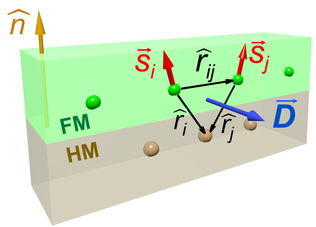
The DMI is an anisotropic exchange interaction favoring a canted spin arrangement and has a net contribution only in systems without a center of inversion. It originates from the spin-orbit coupling (SOC) which acts as a perturbation on localized spin states. Given two neighboring spins and , the DMI contributes to the Hamiltonian locally with a first bilinear energy term described by the following expression:
| (1) |
where is the local DMI vector which can be described by its magnitude , with being the unit vector linking the two neighboring spins and being along the direction of symmetry breaking. This expression is part of a generalized exchange interaction, which relates to the isotropic exchange with exchange constant , i.e. Heisenberg exchange in the case of localized electrons with a direct orbital overlap, or any other direct or indirect exchange described by the above Hamiltonian. Contrary to the Heisenberg type exchange, which favors collinear alignment, the DMI promotes an orthogonal arrangement between and , with a chirality imposed by the direction of .
The DMI was first proposed in the 1950s for antiferromagnets such as -Fe2O3 to account for the existence of a weak ferromagnetism [85, 217]. In the following decades, several magnetic materials, such as spin glasses, orthoferrites, manganites or superconducting cuprates [91, 179, 189, 32, 64, 92], were investigated for their non-collinear or helical magnetism and for the influence of DMI on the magnetic state. An important step towards multilayers, on which this review focuses, was done by Fert [92], where anisotropic pair interactions on surfaces or interfaces were considered.
From an experimental point of view, the development of sophisticated imaging techniques to visualize the magnetic state, such as spin-polarized scanning tunnel microscopy (SPSTM) or spin-polarized low energy electron microscopy (SPLEEM), was crucial for triggering a renewed interest in the topic at the beginning of the century, highlighted in the important works Bode et al. [29], Heinze [113], Heinze et al. [115]. In non-centrosymmetric single crystals with FeSi structure111Often called B20 according to classification of the journal “Strukturbericht”, such as the materials MnSi, FeGe, etc., it was shown that DMI gives rise to skyrmion lattices and other exotic spin textures at low temperature, which could be directly visualized [218, 237, 302].
More recently, the presence of DMI was also demonstrated in thin magnetic multilayers with perpendicular magnetic anisotropy and shown to be localised at the interface between the layers [304, 125, 241, 212]. This interfacial DMI has since received a broad attention from the magnetic community (see e.g. Hellman et al. [116], Gallardo et al. [98]). It is of particular importance in the context of systems consisting of an ultrathin ferromagnetic (FM) film with perpendicular magnetic anisotropy (PMA), in contact with a heavy metal (HM) under- or over-layer. In such a system the DMI arises due to the broken inversion symmetry at the interface between the two materials and the large SOC of the heavy metal atoms, which mediate the interaction between neighboring spins and of the ferromagnet. It follows that the DMI has an interfacial nature with a strength decreasing with the magnetic film thickness. If the symmetry breaking is only due to the interface and symmetry planes or axes are always normal to the film plane, according to Moriya’s rules, the DMI vector , defined at the interface, has to be necessarily perpendicular to the film normal, favoring canting of the out-of-plane magnetisation (see Fig.1).
Bilayers composed of a thin magnetic film with PMA and a heavy metal are particularly interesting from the application point of view, due to the fast domain wall motion driven by an electric current in presence of DMI. Early experiments on current-induced domain wall motion in such systems were not able to fully unravel the driving mechanisms behind such motion. The conventional spin-transfer torque (STT) theory [257, 26] predicts motion in the direction of electron flow, opposite to many observations [214, 215]. On the other hand, the newly proposed spin-orbit torques (SOTs) – caused by the inverse spin galvanic (or Rashba) effect (iSGE) [209, 210] and the spin Hall effect (SHE) [184, 107] – did not have the correct symmetry to drive Bloch walls [140], which were believed to be present in these ultrathin PMA films from purely magnetostatic considerations. This issue was resolved when it was suggested222Here direct imaging of the domain wall chirality [29] played a crucial role. that in presence of DMI, Néel walls, which have a fixed chirality [112, 275], occur instead of the expected Bloch walls (Fig. 2). A series of experimental works later confirmed these findings [86, 240], substantiating the view that DMI-stabilized Néel walls are mostly moved by the SHE torque. Ever since, DMI-based phenomena have created an extremely active research field, often referred to as chiral magnetism.
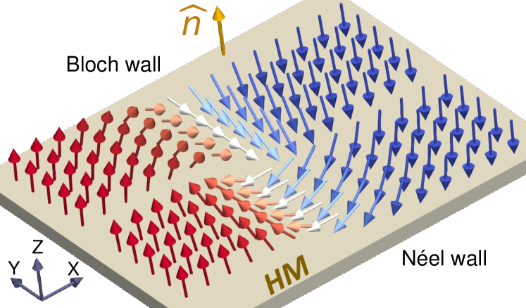
Considering the ferromagnetic film itself isotropic (i.e. without special crystal symmetries, leading to an additional symmetry breaking), the DMI vector simplifies to [217, 70, 275], with a constant describing the strength of the DMI in the film plane ( the vector between the two neighboring spins and is the normal to the film interface). The interfacial DMI can then be thought of as equivalent to an effective in-plane magnetic field which, acting across the domain wall, causes a reorientation of spins from the Bloch configuration into the Néel configuration with a fixed chirality [275, 54]. The strength of the interfacial DMI is then measured as the DMI field [275], to which it is proportional. The sign of dictates the chirality of the Néel domain wall, and, consequently, together with the sign of the spin Hall angle, the direction of the domain wall motion under SHE torque 333The sign of depends on the convention chosen in relation with the Hamiltonian 1 which can be either positive or negative. Throughout this review we use the plus sign in the Hamiltonian, so that positive corresponds to Néel domain walls with the right-handed (clockwise) chirality ( or ), while negative corresponds to Néel domain walls with the left-handed (anticlockwise) chirality ( or ), where up direction is defined by the normal in Fig.2.
Because of the crucial role that the interfacial DMI plays in stabilizing chiral spin structures as well as in attaining extremely efficient domain wall motion, it is of utmost importance for the magnetic community to be able to accurately measure and predict the magnitude and sign of in heavy metal (HM)/ferromagnet (FM) combinations in order to be able to optimize these relevant effects. However, despite a rapidly increasing number of works quantifying the DMI through different experimental techniques, a remarkable spread of data is currently present in the literature and systematic studies or reviews are still rare [62]. Not only are different measurement techniques found to provide contradictory values of for nominally the same system, but controversies are also present when utilizing the same method on nominally identical stacks, or different methods on the same sample [261, 254].
The most commonly used experimental techniques that in recent years have been employed to measure in HM/FM structures can be broadly divided into three categories:
-
1.
Domain wall methods, where is extracted by either measuring the domain wall velocity or energy as a function of an in-plane magnetic field, or by measuring domain wall spacing in stripe domain phases, or by directly measuring the domain wall internal structure;
-
2.
Spin wave methods, where is extracted by measuring the non-reciprocity of propagating spin waves, owing to the presence of DMI, in in-plane magnetised films;
-
3.
Spin-orbit torque methods, where is extracted by measuring the field shift of the out-of-plane hysteresis loop under an in-plane magnetic field.
With this literature review we aim at providing an accurate analysis of the current state-of-the-art regarding measurements of the interfacial DMI constant based on the different techniques summarized above. Therefore, Sections II, III, and IV are devoted to analyze each of the three main classes of techniques mentioned above. In particular, in each section we start with a theoretical background, followed by an overview of the relevant experimental methodologies and then a number of detailed tables with a collection of the relevant results published in the literature. Finally, for each of the three above sections, we will provide a critical discussion of advantages and limitations of each experimental technique. The last section of this review article, Section V, is devoted to a comparison and discussion of the methods and results obtained by the three classes of methods analyzed in the previous sections, as well as to final considerations about open problems and challenges. In particular, we address crucial aspects of the current research, such as the reliability of the different techniques, the choice of material combinations to achieve large/small, negative/positive DMI, and the reasons for the spread of the results (e.g. sample/interface quality, growth conditions and reliability of the measuring techniques).
We anticipate that, with regard to the available literature, it is out of the scope of the present work to give definitive recipes to prepare specific interfaces with a controlled value of DMI, evaluate the level of uncertainty of the different measurement methods, or classify the methods clearly according to their applicability. Therefore, one should consider our synoptic Figs. 28-29 as general guides to explore measurement methods and ranges of values of common heterostructures. We emphasize instead the need for more systematic studies and hope that this review will stimulate the community to tackle metrological aspects of the measurement of the DMI at interfaces.
II Domain wall methods
II.1 Method overview
In ultra-thin films with PMA, Bloch domain walls are magnetostatically favored over Néel DWs444However, Néel DWs become energetically more favorable when the film is patterned into very narrow wires [161].. However, the interfacial DMI manifests itself as a local effective in-plane magnetic field that acts on the domain wall which, when large enough to overcome the magnetostatic energy coming from the shape of the wall, converts Bloch DWs into Néel DWs with a chirality determined by the sign of [275, 54]. By tuning the spin texture of the DWs towards a chiral Néel configuration, the interfacial DMI changes the static and dynamic properties of the DWs [275].
The direct observation of chiral magnetization states in presence of a DMI [113, 29] was the key for understanding the modified DW dynamics. Indeed, first estimates of the DMI strength were obtained by fitting DW energies and numerical simulations of DW imaging in FM mono-/double-layers on tungsten heavy metal substrates [304, 29, 112, 90]. A further experimental technique used to extract a quantitative value of was the measurement of DW velocities driven by an electric current as a function of in-plane magnetic fields [276]. This is not surprising, given the importance of DMI in these systems in the context of current-induced domain wall motion experiments [86, 240]. At the same time, it was proven that could also be inferred by measuring magnetic field driven DW velocities [125, 121]. , and thus , is extracted by analyzing the dependence of the DW velocity on the in-plane magnetic fields, which - added or subtracted to the - can enhance or reduce the DW speed.
Following these early investigations [240, 276, 125, 121], several further works have used DW motion, induced by either current or field, to estimate the strength and sign of the interfacial DMI in different material systems. Nucleation of reverse domains, which is a necessary step to study the motion of DWs, was shown to be dependent on [231], which established another path to access the magnitude and sign of . Finally, also the static properties of domains were shown to be altered by the presence of DMI. This was observed from two points of view: firstly, the domain width is altered due the modification of the DW energy originated from DMI [216]. Secondly, the DMI affects the stability of reversed domains and their field of annihilation [119]. Both effects have been used to estimate the magnitude of .
DW dynamics in the presence of DMI can be understood making use of analytical 1D models. One-dimensional DW models have been established as useful tools to support computationally costly micromagnetic simulations as well as to interpret experimental results. As the name suggests, the 1D models for DW dynamics are based on the approximation that the magnetization varies along one direction only, namely the axis of a narrow wire, usually identified with , as depicted in Fig. 3.
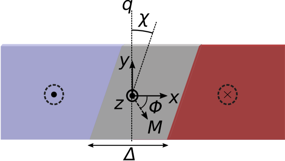
The origins of the 1D models can be traced back to the original description of Bloch walls by F. Bloch [28]. The simplest form of the 1D model was introduced by Walker and Slonczewski [250, 194] in the 1970s555 The 1D model was reported earlier by L. R. Walker, Bell Telephone Laboratories Memorandum, 1956 (unpublished). A description of this work can be found in J.F. Dillon Jr., Domains and Domain Walls, in: Magnetism, Vol. III, edited by G. T. Rado and H. Suhl (Academic, New York, 1963)., to study DW dynamics in PMA materials under the influence of an applied perpendicular field. Here DW dynamics was described in terms of two time-dependent variables (see Fig. 3): the DW position along the wire axis, and the DW angle , defined as the in-plane (–) angle of the internal DW magnetization with respect to the positive axis666According to these conventions, () corresponds to a right (left) handed chiral Néel DW, while corresponds to a Bloch DW.. The model was later extended by Sobolev et al. [259, 258] to describe DW dynamics in PMA materials under in-plane fields. Thiaville et al. [273] next adapted the 1D model to systems with in-plane magnetic anisotropy, using the domain wall width as an additional time-dependent variable in a revised model.
More recently, several other contributions have been included in the 1D model to take into account newly discovered effects, such as the STTs [306, 274], the SOTs [111, 251, 35, 198, 200] (see Eq. 3), and the DMI [275, 86, 198]. In this context, is then derived according to 86:
| (2) |
where is the saturation magnetization, and is the DW width parameter, with being the exchange stiffness and the effective perpendicular anisotropy constant, corresponding to the intrinsic perpendicular anisotropy constant decreased by the demagnetizing energy .
Additions of thermal fluctuations [196] and of spatially dependent pinning [65] helped to make the 1D model more realistic. Furthermore, considering experiments of fast current-driven DW motion [241], Boulle et al. [36] proposed to include DW tilting as an additional time-dependent variable (defined as the angle of the DW normal plane with respect to the positive -axis), which led to the development of the model. Very recently the 1D model was extended to implement all four collective coordinates, namely , with the aim of improving the agreement with experimental observations and micromagnetic simulations when large in-plane fields are applied [220]. The same authors later showed that the simple two coordinate model can grant higher accuracy when combined with an ansatz (which links collective coordinates to magnetization components) that takes into account magnetization canting within the domains under an in-plane field [219].
II.2 Theory and models
II.2.1 Current-driven domain wall motion
The driving mechanism behind the current-induced motion of DWs in heavy metal/ferromagnet bilayers with PMA is now widely believed to be due to a combination of SHE and DMI, while the iSGE torque is considered to be negligible [86, 240, 199], as the latter acts to stabilize Bloch walls [210], and does not have the correct symmetry to drive DWs directly [86, 140]. The SHE in the heavy metal converts an in-plane charge current into a transverse spin current that gives rise to spin accumulation at the interface between the two layers, with consequent spin-current diffusion into the ferromagnet. This spin-current can interact with the local magnetization by exerting a torque on it, known as the SHE spin-orbit torque (SHE-SOT)777To be precise, field-like and damping-like torques can occur as a result of iSGE or SHE effects.. According to the 1D model, the amplitude of the effective field associated with the SHE-SOT is expressed as [275, 140]:
| (3) |
where is the spin Hall angle, is the electron current density, is the thickness of the ferromagnetic film, and is the internal in-plane DW angle as defined in Fig. 3. As mentioned earlier, the SHE-SOT can move DWs only if they possess a Néel component (i.e. ) in their spin structure, due to the interfacial DMI. The direction in which DWs move with current depends both on the sign of the spin Hall angle , determined by the spin-orbit coupling constant of the heavy metal, and on the sign of (i.e. on the chirality of the DW). Micromagnetic simulations and 1D model predict that the maximum velocity of DWs driven by the SHE-SOT increases with the magnitude of , and saturates for larger currents showing a clear plateau [275, 234, 176].
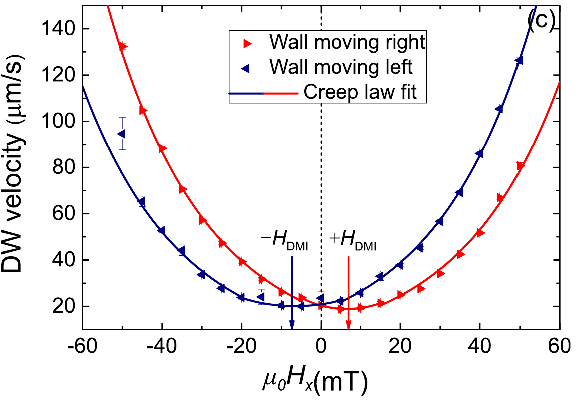
The current-driven DW dynamics is dramatically affected by the application of an in-plane magnetic field along the current direction. It is indeed due to this that DW velocity measurements as a function of provide a means to quantify . Given a fixed , it is observed that Néel DWs with the same chirality and have the same velocity when , while they move with different velocities under a non-vanishing . In particular, for a given sign of , the DW type for which is parallel to moves faster while the other kind, where partially compensates , slows down with respect to its velocity at . The situation is reversed by changing the sign of the applied . This remarkable behaviour has an important consequence: both DWs stop moving for a certain , equal in strength but opposite in sign for and DWs respectively, as schematically shown in Fig. 4.
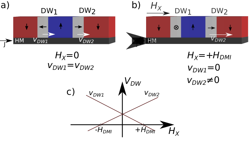
The applied under which these Néel DWs stop moving – typically referred to as the “compensating” or “stopping” field – is the field that, opposing the DMI, restores a Bloch DW configuration, for which indeed no motion is expected via SHE-SOT. As such, this “compensating” field can be considered equivalent in strength (but opposite in sign) to the acting locally across the DWs. In other words, because of the change in the DW internal magnetization angle [241], Néel DWs move faster or slower depending on whether the effective in-plane field experienced by the DW is enhanced () or decreased (), respectively. In the latter case, DWs stop moving for , when they become Bloch walls, and they reverse direction of motion for , when the Néel configuration is re-established but with an opposite chirality. However, identifying with is valid only if conventional STT, due to the spin-polarized current in the ferromagnet, [257, 26] can be neglected. When a significant STT is present, the relationship between the and in the 1D model becomes [86, 240]:
| (4) |
where is the Bohr magneton, is the spin current polarization, and is the gyromagnetic ratio. Eq. 4 implies that can depend on the amplitude of the current used to drive DWs. When only a modest dependence of on is observed, as for instance in Ryu et al. [242], Karnad et al. [134], it is possible to conclude that the contribution from STT is small. In any case, once is determined, the magnitude of is derived through Eq. 2, while its sign is inferred from the direction of the DW motion and the sign of the spin Hall angle .
The dependence of the DW velocity on an in-plane field for a fixed current density can be analytically described in the context of the 1D model, taking into account STT, SHE-SOT and DMI [275, 86, 240]. As seen in Fig. 4, the DW velocity is expected to be approximately linear with around the “compensating” field , and some experimental works derive by linearly fitting the data [240, 276]. In some cases, it has been observed that the DW velocity remains small or null in a quite large range of around [242, 186, 185], consistent with thermally activated creep regime, and strong pinning effects. To account for it, the 1D model has been extended to include an effective pinning potential both without [242, 185], and with thermal fields [186] to describe the influence of thermal fluctuations. In both cases, the modified 1D model has provided good agreement with the experimental data and has been used to extract . The range of values for which the DW velocity is negligible has been observed to decrease upon increasing the current density, due to a reduced influence of pinning [242].
A few papers have shown that can also be quantified through current-driven DW dynamics by measuring the dependence of the DW depinning efficiency, rather than the DW velocity, on the in-plane field [95, 144]. The efficiency of DW depinning is defined as:
| (5) |
and is measured as the slope of the out-of-plane depinning field as a function of . The DW depinning efficiency changes as a function of , due to the corresponding variation of the DW internal structure. In particular, is found to vanish at a certain , equal in strength but opposite in sign for and DWs. Similarly to what was already discussed for the DW velocity dependence on , this in-plane field for which represents the field at which a Bloch DW configuration is restored, and can thus be identified with .
II.2.2 Field-driven domain wall motion
The simplest and most common way to move DWs in PMA materials is by applying a perpendicular field . To minimize the Zeeman energy associated with , domains with magnetization along the field direction expand at the expense of the others, leading to DW motion. Field-driven DW dynamics are typically classified into three distinctive regimes – creep, depinning, and flow – which occur in succession upon increasing , as shown in Fig. 5a.
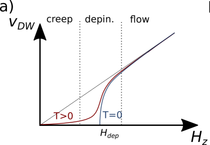
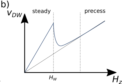
For sufficiently low driving fields DWs move in the thermally activated creep regime where they interact strongly with disorder, and their velocity grows exponentially as [174, 50]. Upon increasing above a critical value, known as the depinning field , disorder starts to become irrelevant and the DW velocity grows as [50], with being the depinning exponent at as in Fig. 5a. Finally, for the DW enters the flow regime where the velocity increases linearly with up to the so-called Walker field , which marks a significant decrease in DW velocity, due to a change in its internal dynamics [207]. For the DW recovers a linear flow with , albeit with a reduced mobility .
With the exceptions of a few works [280, 127, 229, 3, 263, 163], the DMI has been mostly quantified through experiments of field-driven DW motion in the creep regime, which is addressed below. Methods to extract the DMI from DW dynamics in the flow regime will be discussed later.
Creep regime
In the creep regime, DWs are driven by modest fields (typically down to a few percent of ) and move slowly by thermal activation, interacting strongly with disorder of various origin (pinning defects, film thickness variations, inhomogeneities, etc). The DW creep dynamics is understood in terms of the motion of a one-dimensional elastic line in a two-dimensional disordered potential. The dependence of the DW velocity on the applied field is described by the so-called creep law [174, 50]:
| (6) |
where is the characteristic speed proportional to the attempt frequency for DW propagation, is a scaling constant, and is the scaling exponent for the 1D elastic line.
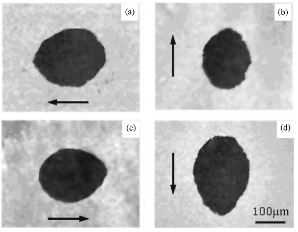
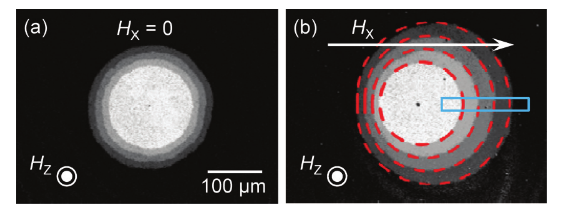
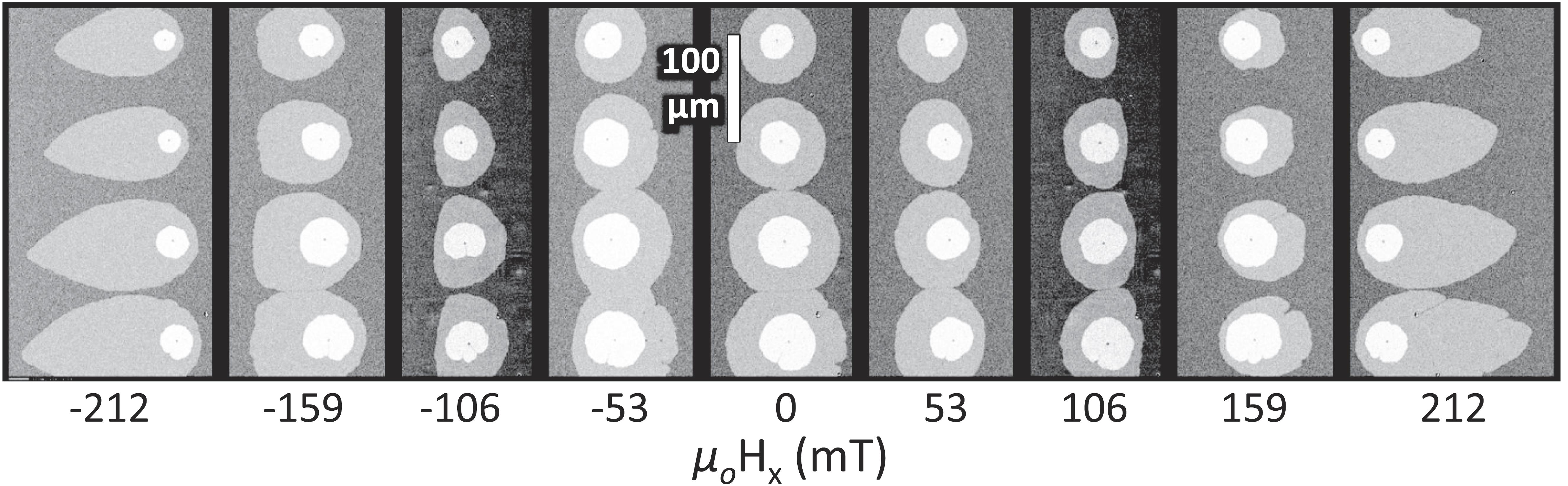
Creep motion of DWs driven by a perpendicular field is significantly altered by the simultaneous presence of an in-plane field , similarly to what already discussed for the current-driven case (see Sec. II.2.1). Indeed, it is observed experimentally that when a circular magnetic bubble expands under the application of only, the radial symmetry is maintained and the bubble grows isotropically – thus retaining its original shape. However, the symmetry is broken when the bubble is expanded under the application of both and , as Néel and DWs acquire different velocities along the direction of the applied . This circumstance was first observed in Kabanov et al. [129] for continuous films of Pt/Co/Pt (see Fig. 6), mentioning the interfacial DMI as a possible origin. Only later it was fully understood and modelled in the context of DW creep.
The first model proposed to explain the asymmetric motion of Néel DWs with the in-plane field [125], suggested to modify the creep law (Eq. 6) by changing the scaling parameter to take into account the dependence of DW energy on the in-plane field [125]:
| (7) |
where is a scaling constant and is the DW energy density. The dependence of DW energy density on the in-plane field has been calculated as [275, 125]:
| (8) |
when the condition is satisfied. In this case the effective field acting on the DW is not strong enough to fully convert it into a Néel DW. Otherwise, for higher fields and fully Néel DWs the expression becomes:
| (9) |
In these equations, is the Bloch DW energy density, is the domain wall width parameter, and is the DW shape anisotropy energy density888 represents the fact that Bloch DWs are magnetostatically more stable in the absence of DMI due to the high PMA of the films., with the demagnetising factor of the DW given by , with the magnetic film thickness [270]. In other words, this model predicts that the effective in-plane field acting locally on the Néel DWs on either side of the bubble can be increased (decreased) if and have the same (opposite) sign, resulting in smaller (larger) DW energy and thus a faster (slower) DW, just as for the current-driven case (see Fig. 7).
The field at which Néel DWs are converted into Bloch DWs is then equal in magnitude but opposite in sign for and DWs, respectively. It is important to notice that, differently from the current-driven case, field-driven Bloch DWs do not stop moving under the in-plane field , since the perpendicular field keeps expanding the magnetic bubble to minimize Zeeman energy. Rather, in field-driven experiments, corresponds to a minimum in DW velocity. In this simple model, the velocity for each type of DW should be symmetric around its own minimum, as in Fig. 7c, although in many experimental cases it is not. It follows that in the absence of DMI, i.e. when the bubble DW is in the Bloch configuration, both sides of the bubble have the same velocity dependence with , show a minimum at and are symmetric around [142]. This model can be used to fit the dependence of bubble DW velocities on in-plane field using three fitting parameters: , , and itself. Alternatively, the scaling parameters and can be extracted separately as the intercept and gradient of a linear fit to the curve vs. for , thus leaving as the only fitting parameter of the dependence on . Once has been determined, the magnitude of is derived through Eq. 2, while its sign is inferred from the orientation of the bubble asymmetry with respect to the direction.
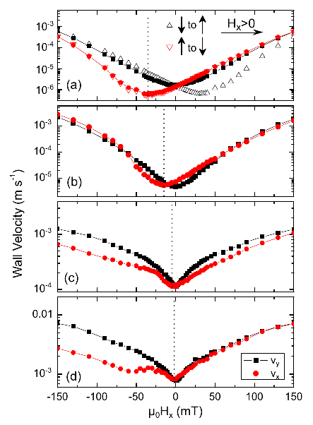
This modified creep model, in which the in-plane field affects DW dynamics only through a variation of domain wall energy, has been successfully applied to fit several experimental data and estimate the interfacial DMI constant [125, 121, 228, 301, 138, 287, 147, 166, 253]. However, for a growing number of experiments, as for instance in Fig. 8, the model fails to provide an adequate description of the data, which often show an asymmetric behavior around the minimum velocity [169, 128, 168, 261, 226, 44, 144, 256, 254], a local peak in velocity [169, 261, 12], or even a maximum in velocity in the flow regime [280].
To explain these non-symmetric results, several different mechanisms have been suggested. Jué et al. [128] proposed to neglect any DW energy contribution, and consider a DW chirality-dependent damping, which acts as a dissipative SOT on the DW: this damping would modulate the attempt frequency for DW motion, and would thus modify the characteristic speed of the creep law (see Eq. 6). On the contrary, Lavrijsen et al. [169] suggested that chiral damping could not be an explanation of the asymmetry of their own results, as was found to be symmetric with respect to . The importance to consider possible dependences on both creep parameters and (not necessarily related to chiral damping) has been highlighted in Balk et al. [12], Shepley et al. [256]. While Shepley et al. showed that the dependence on is asymmetric for both and , Balk et al. modelled their results through a modified creep law that takes for both parameters a dependence on into account. By combining Eqs. 6, and 7, with their expression for , they were able to fit velocity vs curves that showed a local peak around , introducing a local anisotropy due to pinning , and having and as fitting parameters.
Several analytical and numerical studies were devoted to understanding these features. Kim et al. [141] attributed the asymmetry in the DW energy density , to the asymmetric variation of the DW width with , later confirmed by micromagnetic simulations [246]. Lau et al. [168] described the velocity asymmetry in terms of the Wulff construction, which yields a methodology to determine the shape of a magnetic bubble, although it does not explicitly provide a model for the velocity as a function of in-plane field. They also speculated that nucleation and annihilation of Bloch lines may be responsible for a peculiar flattening of magnetic bubbles, which could in turn cause the observed velocity asymmetry. This again was confirmed through micromagnetic simulations by Sarma et al. [246]. Pellegren et al. [226] argued that under an applied magnetic field , where the DW energy density becomes anisotropic with respect to the DW orientation in the film plane, the correct elastic energy that should be considered to describe the creep regime does not simply identify with , as typically assumed in the phenomenological model of creep [174]. Rather, to reproduce the asymmetry in their velocity curves, they propose that should be replaced by the DW stiffness , with , where is the azimuthal angle of the DW normal. Interestingly, the value extracted using this stiffness model was found to be higher than the field at which the minimum in velocity is observed. In a later work [167], the same authors proposed to upgrade the stiffness model, by taking into account a possible variation of the characteristic speed with , which they also speculate could be due to a chiral damping mechanism. Through this improved model, they could fit velocity curves as a function of that are not only asymmetric about the minimum, but also show a crossover between DW velocities at opposite sides of the bubble. More recently, another model was advanced by Shahbazi et al. [254] to explain the presence of both asymmetry and DW crossover in the velocity curves. Here, the DW depinning field is allowed to vary with in a way determined from micromagnetic simulations. Notably, this work shows that the velocity minimum underestimates , as was also found for the stiffness model [226]. This is also confirmed by Hartmann et al. [110] and Géhanne et al. [100]: the former reconsidered the change of the DW stiffness due to deformation as an angular shape, and minimizing the energy of the system with a semi-analytical approach they could calculate the velocity profile and show that the minimum of the velocity does not occur at . The latter showed that can also modify the characteristic length scale of pinning, in strong correlation with the DW width, again implying that the minimum of the velocity could not correspond to the field.
Flow regime
According to the 1D model [275], the presence of DMI significantly increases the Walker field . Indeed, in samples with a strong enough DMI to convert the wall to a fully Néel form, is proportional to :
| (10) |
where is the Gilbert damping constant [275]. The DW velocity at Walker breakdown can thus be expressed as:
| (11) |
where is the gyromagnetic ratio. In contrast to the prediction of the 1D model, it is found experimentally and confirmed by 2D micromagnetic simulations that in samples with large DMI, the DW velocity does not decrease at fields larger than , but instead reaches a plateau [229, 298, 3]. This fact originates from the complex meander-like structure that the DW adopts at velocities above , with continuously nucleation and annihilation of pairs of vertical Bloch lines [298, 229]. Measurements of this roughly constant velocity, which corresponds to , provide a simple way to determine for samples with large DMI. A combination of experiments and modelling has been used to show that is also associated with the value of at which the end of the plateau is reached [163].
In other works [280, 229, 3, 263] measurements of the minimum DW velocity as a function of in the flow regime have also been used to quantify : in the flow regime the DW velocity depends only on DW width (not DW energy) and this assumes the minimum value when the DW is Bloch. Indeed, it has been shown that under certain conditions the 1D model provides an expression for the DW velocity that exhibits a parabolic dependence on [146].
II.2.3 Equilibrium stripe domain pattern
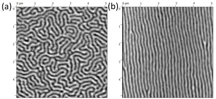
The demagnetized state of PMA materials consists of a complex domain pattern, usually in the form of labyrinth structures of domains pointing either up or down. If the thickness of the sample is very small, the equilibrium domain width can exceed the sample dimensions and such structures are not expected. Examples of the typical patterns are shown in Fig. 9 for a multilayer of Pt/Co/Al2O3, taken from Legrand et al. [172]. The exact demagnetized pattern depends on the direction and the history of the applied field: when an out of plane field is applied, a maze domain structure is created (Fig. 9a), while for an in plane field, domain walls remain almost parallel and typically form a stripe structure (Fig. 9b). In the latter, the width and the density of domains can be used to estimate the domain wall energy. As suggested by the theory developed for infinite parallel stripe domains [193, 158], the domain width is a function of the domain wall energy, which includes magnetostatic, anisotropy, Zeeman, and exchange terms. Néel walls, favored by DMI, have a reduced energy and, consequently the DMI markedly affects the equilibrium domain width.
For domain widths much larger than the domain wall width, as is generally the case for PMA materials, the magnetostatic contribution comes only from the surfaces charges at the top and bottom surfaces, so that DW energy is calculated as:
| (12) |
where is the same angle of the internal DW magnetization defined in Fig. 3. The minimization of the energy with respect to the domain width and core angle gives the value of the equilibrium domain width: a critical value is obtained. For the preferred configuration is a Néel wall and for it gradually transforms into a Bloch wall as approaches zero.
Initially, this method was limited to Néel walls only, with , and hence , so that the DW energy density simplifies to . Later, the inclusion of the angle of the wall in Eq.12 removed this limitation [203, 177]. A further improvement took into account the dipolar terms coming from the internal structure of the DW or/and from the DW interaction [177]. This is important in thicker samples, as the dipolar energy causes the internal magnetization to vary along the thickness, even in the presence of DMI. To account for all these situations, the model was extended allowing a different angle for each layer of the sample [175].
The analytical expression for the DW energy as a function of the periodicity of the domains, which is twice the domain width, is
| (13) |
where is the thickness. From the experimentally obtained domain width one can then calculate the domain wall energy, and estimate the DMI constant using one of the previously derived approximations.
This general method has been applied in three different ways: comparisons to micromagnetic simulations [216, 172], analytical estimations [289, 300, 290, 288], and scaling of the energy of an experimental image [8].
II.2.4 Magnetic stripe annihilation
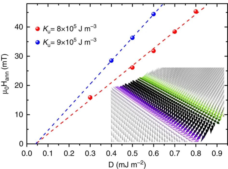
Two parallel domain walls in a thin film with strong enough DMI are homochiral Néel walls. Since the chirality of the domain walls is the same, either left-handed or right-handed, the core magnetization of those parallel domain walls point in opposite directions. Such a pair of domains constitutes a topological structure. This situation is different from the case of absence of DMI, where the core magnetization of the Bloch walls point in the same direction but not in a fixed orientation. The annihilation of these two parallel Néel walls depends on the strength of the DMI due to the topological configuration. This fact was confirmed by simulations [197, 119]. To annihilate the walls an out of plane field is applied that reduces the size of the domain disfavored by the field. This domain achieves a minimum size until the walls meet as a so-called “winding pair” to form a wall, which annihilates when a given value of the out-of-plane field is exceeded. From the determination of the field of annihilation and the minimum domain width the DMI can be extracted when compared with the corresponding simulations [119]. An example from [25] of the annihilation field dependence on DMI calculated by means of micromagnetic simulations can be seen in Fig. 10. More recently, a formula for the minimum width of stripe domains was derived [177], using the analytical formulation discussed in the previous section. This allowed the extraction of the DMI value without the performance of systematic micromagnetic simulations.
The analytical formula for the domain wall energy obtained from the minimum domain width is given by:
| (14) |
As in the previous method this allows extracting the value of the domain wall energy density which is also a function of the DMI constant. Using the same expressions for the energy density as given in the previous section, one can estimate its value.
II.2.5 Nucleation field
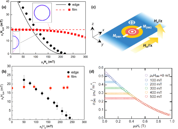
As stated above, the energy of a domain wall is reduced by the presence of DMI. This modification also affects the energy barrier relevant for nucleation of reversed domains. Pizzini et al. [231] showed that the nucleation process is affected by the presence of DMI. They distinguished between nucleation at the edge of the patterned sample and in the center of the magnetic film. They showed that the nucleation of reversed domains at the edge depends on the value of the in-plane applied field and it is asymmetric with respect to the combination of the DMI sign and the in-plane field direction. The nucleation is favored at the edge of the sample having a nucleated wall with the core magnetization in the direction of the in-plane field. The half-droplet model [284], applied in the paper, describes the nucleation of a magnetic domain at the side edge under the application of an in-plane magnetic field. The out-of-plane nucleation field for a reversed domain is:
| (15) |
where is the domain wall energy associated with the bubble, is the temperature and is the factor related to the waiting time according to where is the attempt frequency. The DW energy is a function of the in-plane field and the DMI constant. From the best adjustment of their numerical model to the experimental results, they were able to estimate the DMI constant in Pt/Co/AlOx.
In the case of a bubble domain away from the edges, Pizzini et al. [231] concluded that the Zeeman energy gained within the half droplet having a DW magnetization component parallel to the in-plane field is compensated by the loss of energy within the half droplet with opposite magnetization (see the orientation of the magnetization in Fig. 11(b)), while this is not true for an incomplete bubble nucleated at the edge. Therefore, the nucleation field for a complete bubble is independent of the in-plane field value. This fact agrees well with their model shown in Fig. 11(a) and their measurements shown in Fig. 11(b).
More recently, Kim et al. [153] realized that such an argument does not hold for bubbles in films above a critical in-plane field value, corresponding to the DMI field, where the energy of the bubble is altered due to the fact that the magnetization at its boundary aligns with the in-plane field. Hence, the picture in Fig. 11(c) is no longer valid. This fact leads to a reduced value of the bubble magnetic energy and an associated reduction of the nucleation field when the in-plane field value is increased beyond the DMI field. This was in agreement with their numerical calculations as shown in Fig. 11(d). This fact was not observed in Pizzini et al. [231] due to the large DMI field in the samples studied in their work.
Therefore, the critical field above which a change from a constant nucleation field to a field dependent nucleation is observed is a measure of the DMI constant, since it coincides with the DMI field . Experimentally, this can be determined from the dependence of the out-of-plane nucleation field on the in-plane field.
II.2.6 Domain wall stray fields
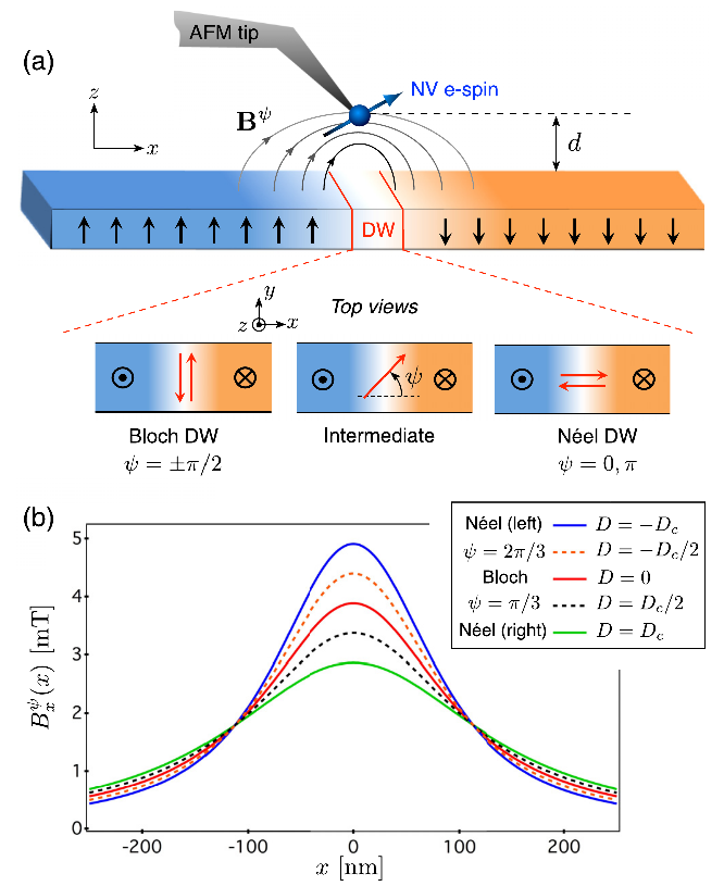
Another method taking into account the static DW structure is the direct measurement of the stray field in the DW. The stray field has a typical profile along the axis perpendicular to the DW including information on the angle and the strength and sign of (see Fig. 12). This method is limited to low values of , i.e. when a significant angle is present. is the critical value above which formation of fully oriented Néel walls occurs ( is the film thickness). Therefore only samples with relatively small can be measured since is typically on the scale of 0.2 mJ/m2 (see Tab. 12). For samples with larger DMI, where fully oriented Néel walls are present, only a lower limit of can be given together with its sign [272]. Since DW widths are of the order of 5-10 nm, the stray field profile determination requires an excellent spatial resolution, which was experimentally tackled by nitrogen vacancy (NV) magnetometry [104].
II.2.7 Domain wall internal structure imaging
With the progress in the development of advanced microscopy techniques with nanometric resolution and magnetic contrast, it has become possible to access not only the size and distribution of magnetic domains, but also to study the detailed structure of domain walls. As discussed in the previous sections, the domain wall structure is influenced by the presence of DMI, so that from a detailed identification of the wall structure one can in principle quantify the DMI strength. Basically four methods for spin sensitive imaging were used in literature: pioneering works were performed by spin-polarized scanning tunneling microscopy/spectroscopy (SP-STM/STS), the most quantitative works were done by spin-polarized low-energy electron microscopy (SPLEEM) and in a few more recent works Scanning electron microscopy with polarization analysis (SEMPA) and Lorentz-transmission electron microscopy (L-TEM) were employed.
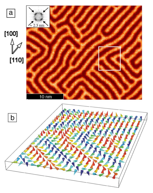
Some of the earliest evidences that the DMI influences domain wall energies and alters DW configurations was obtained from SP-STM of ultrathin magnetic films deposited on heavy metal substrates such as single atomic layers of Mn or Fe on W(110) substrates [29, 112, 115]. These methods provide information on the magnetic order at the atomic scale. In order to extract the parameters entering the total energy of the observed non-collinear spin structures, such as the DMI constant, simulations of the images (see Fig.13) based on models describing the tunneling process in the tip [271] and density functional theory were performed [291]. Since the computational cost of ab initio models is large, simplified approaches were devised, combining them with Monte Carlo or micromagnetic calculations [114, 112]. Successively, using SP-STM, Pietzsch and Wiesendanger [230], Meckler et al. [202, 201] concentrated on spin spiral domains in these bilayers and showed that the magnetic structure of the Fe double layer grown on W(110) is an inhomogeneous right-rotating cycloidal spin spiral. Meckler et al. [202] extracted the magnitude of the Dzyaloshinskii-Moriya vector from the experimental data using analytical micromagnetic calculations. The result was then confirmed by comparison of the measured saturation field along the easy axis to the respective value as obtained from Monte Carlo simulations.
More recently, spin-polarized low-energy electron microscopy (SPLEEM) has been successfully exploited to achieve a quantification of the DMI strength in different systems [54, 52, 55, 53, 295]. While first works give only an estimate of the DMI constant, a remarkable development towards quantitative values is observed in literature. Here, the HM thickness dependent transition from chiral Néel walls to achiral Bloch walls is investigated in wedge samples. From the critical thickness a quantitative estimate of the DMI strength is obtained. In addition to SP-STM and SPLEEM, also L-TEM [99] and SEMPA [66, 156, 205] have been used to quantify the DMI strength by comparing the measured and the calculated profiles of the domain walls. In most cases micromagnetic analytical calculations or simulations of the DW energy or strayfield are employed.
II.3 Experimental results
II.3.1 Current-driven domain wall motion
| FM | Bottom NM | Top NM | HDMI | Ref | ||
| (nm) | (nm) | (nm) | (mT) | (mJ/m2) | (pJ/m) | |
| Co(0.3)/Ni(0.7)/Co(0.15) | Pt(1) | TaN(5) | 60 | n.a. | n.a. | 240 |
| Pt(1.5) | 190 | n.a. | n.a. | |||
| Pt(3) | 240 | n.a. | n.a. | |||
| Pt(5) | 220 | n.a. | n.a. | |||
| Co(0.3)/Ni(0.7)/Co(0.15) | Pd(5) | TaN(5) | 12 | n.a. | n.a. | |
| Ir(3) | 18 | n.a. | n.a. | 242 | ||
| Pt(5) | 140 | n.a. | n.a. |
| FM | Bottom NM | Top NM | HDMI | Sign | Ref | ||
|---|---|---|---|---|---|---|---|
| (nm) | (nm) | (nm) | (mT) | (mJ/m2) | (pJ/m) | ||
| Co20Fe60B20(1) | Hf(2.6–6) | MgO(2) | n.a. | 0.38 – 0.05111The highest and lowest DMI values reported do not necessarily correspond to the extremes of the bottom layer thickness range (for instance the highest DMI value could occur at mid thickness range). | 0.38 – 0.05111The highest and lowest DMI values reported do not necessarily correspond to the extremes of the bottom layer thickness range (for instance the highest DMI value could occur at mid thickness range). | - | 276 |
| Ta(0.5–1.3) | n.a. | 0.08 – 0.07111The highest and lowest DMI values reported do not necessarily correspond to the extremes of the bottom layer thickness range (for instance the highest DMI value could occur at mid thickness range). | 0.08 – 0.07111The highest and lowest DMI values reported do not necessarily correspond to the extremes of the bottom layer thickness range (for instance the highest DMI value could occur at mid thickness range). | - | |||
| TaN(0.4–6.6) | n.a. | 0.04 – 0.20111The highest and lowest DMI values reported do not necessarily correspond to the extremes of the bottom layer thickness range (for instance the highest DMI value could occur at mid thickness range). | 0.04 – 0.20111The highest and lowest DMI values reported do not necessarily correspond to the extremes of the bottom layer thickness range (for instance the highest DMI value could occur at mid thickness range). | + | |||
| W(2.1–3.6) | n.a. | 0.24 – 0.37111The highest and lowest DMI values reported do not necessarily correspond to the extremes of the bottom layer thickness range (for instance the highest DMI value could occur at mid thickness range). | 0.24 – 0.37111The highest and lowest DMI values reported do not necessarily correspond to the extremes of the bottom layer thickness range (for instance the highest DMI value could occur at mid thickness range). | + | |||
| Co20Fe60B20(1) | Ta(5) | MgO(2) | 7.8 | 0.06 | 0.06 | + | 186 |
| Co20Fe60B20(0.8) | Ta(5) | MgO(2) | n.a. | 0.03 | 0.02 | - | 134 |
Measurements of current-driven DW motion are performed in wires with typical widths ranging between 1 m and 5 m and lengths of a few tens of m. Usually, the magnetization in the wire is initially saturated by applying an out-of-plane field . is then removed and a current pulse (with duration of a few tens of ns) is applied either directly to the wire or to an Oersted line patterned on top of the wire. In either case the current pulse nucleates a reversed magnetic domain and a DW is thus injected into the wire. Alternatively, one can use a magnetic field pulse to generate domains in injection pads, and inject them in the wires.
For measurements of DW velocities, current pulses are applied to the wire to move a DW, while the DW position along the wire is imaged by magneto-optical Kerr effect (MOKE) microscopy in polar configuration. The number and duration of the applied current pulses is chosen to obtain a significant displacement of the DW, at least over a few m. Typical values of current densities fall in the range between 1010 A/m2 and 1012 A/m2. The velocity of the DW is calculated as the ratio between the current-induced DW displacement and the total duration of the pulses. Finally, velocities are measured for both and DWs under different strength of , keeping the current density fixed, in order to determine the “compensating” field of Fig. 4.
| FM | Bottom NM | Top NM | HDMI | Sign | Ref | ||
| (nm) | (nm) | (nm) | (mT) | (mJ/m2) | (pJ/m) | ||
| Co(0.36) | Pt(4) | Pt(1) | 37 | 0.24 | 0.09 | - | 95 |
| Co(0.36) | Pt(4) | Pt(2) | 12.5 | 0.10 | 0.04 | - | |
| Co(0.5) | Pt(4) | Pt(2) | 11 | 0.09 | 0.04 | - | |
| Co(0.5) | Pt(2) | Pt(4) | 3 | 0.03 | 0.02 | - | |
| Co(0.8) | Pt(4) | AlOx(1.9) | 40 | n.a. | n.a. | ||
| Co(1) | Pt(5) | Gd(2) | 280 | 1.00 | 1.00 | - | 280 |
| Co(0.93) | Pt(4) | AlOx(2) | 99 | 0.54 | 0.50 | - | |
| Co(1.31) | 54 | 0.48 | 0.63 | - | 185 | ||
| Co(1.37) | 48 | 0.47 | 0.64 | - | |||
| Co(0.9) | Pt(2.5) | Al(2.5) | 107 | 0.87 | 0.78 | - | 144 |
| Co(0.9) | Ti(2.5) | 197 | 1.42 | 1.28 | - | ||
| Co(0.9) | W(2.5) | 183 | 1.35 | 1.22 | - | ||
| Co(0.5) | Pt(1.5) | 0 | 0 | 0 |
For measurements of DW depinning efficiencies, a constant current density is applied continuously to the wire for a given in-plane field , while the out-of-plane field is ramped up until DW motion is detected by MOKE. The DW depinning efficiency for a given is then determined from the slope of the depinning field as a function of . Modest current values are used, up to about 1010 A/m2, in order to exclude Joule heating effects. Finally, is measured for both and DWs under different strength of , and is determined as the “compensating” field for which .
Measurements of current-driven DW motion as a function of the in-plane field have been used to extract in several material stacks, with Co/Ni/Co, Co20Fe60B20 or Co as ferromagnetic films, different heavy metals as underlayers and either a heavy metal or an oxide as overlayers. Tables 1, 2, and 3 present a summary of the DMI values measured for Co/Ni/Co, CoFeB, and Co, respectively.
For Co/Ni/Co films (see Table 1), the DMI seems to increase upon increasing the thickness of the Pt underlayer [240], while it is very low when using Pd or Ir as underlayers [242].
For CoFeB films with Ta and MgO as underlayer and overlayer (see Table 2), the DMI values, generally small, are spread not only in magnitude, but also in sign [276, 186, 134]. This can be explained by the fact that the two interfaces contribute with small and opposite DMI values, and that the DMI at the CoFeB/oxide interface strongly depends on its oxidation state. Furthermore, Karnad et al. [134] find different signs of DMI for Ta/CoFeB/MgO depending on whether they measure DW motion driven by current or field (see table 5 for the field-driven case). Among the underlayers used with CoFeB, W provides the highest (positive) DMI [276].
Finally, for Co films, Pt is the only underlayer investigated, while overlayers are either oxides or metals (see Table 3). In the symmetric structure Pt/Co/Pt, where no DMI is expected if the two interfaces are identical as experienced with epitaxial layers, either negative [95] or vanishing [144] DMI values are measured. This lack of perfect compensation depends on growth conditions, oxidation of the interfaces, and many other experimental conditions. For all the other stacks the DMI is always negative and largest in magnitude when using Ti as overlayer [144].
II.3.2 Field-driven domain wall motion
Experiments of field-driven DW dynamics are mostly performed in continuous films where magnetization reversal proceeds by nucleation and growth of magnetic bubble domains. Only few works report studies of planar DW dynamics (i.e. straight walls) in continuous films [226, 147] or in m-wide wires [127, 144]. The magnetization in the continuous film/wire is initially saturated by applying a perpendicular field . A bubble domain (or a domain separated by a planar DW) is then nucleated by applying a short pulse in the opposite direction, through either a coil or an electromagnet. The bubble domain (or the planar domain) is expanded under simultaneous application of continuous (from an electromagnet) and pulsed or continuous (from a coil or an electromagnet). The initial and final positions of the DW are imaged through MOKE microscopy in polar configuration. Typical bubble growths are in the range of at least a few tens of m, to avoid coalescence with other bubbles. The velocity of the DW is measured along the direction of the applied and is calculated as the ratio between the DW displacement and the total time during which is applied – whether in pulses or continuously. Finally, velocities are measured for both and DWs (i.e. DWs on opposite sides of the bubble) under different strength of , upon keeping constant. In this way velocity vs curves are constructed for both DWs and is determined either through fitting with one of the modified creep formula previously discussed (II.2.2), or simply by finding the field for which the velocity is minimum.
Regarding the strength of the applied fields, values differ greatly depending on the material and DW motion regime investigated. For measurements in the creep regime only modest are needed – usually of a few mT depending on the depinning field – while of hundreds of mT are used to drive DWs in the flow regime. The maximum values of applied depend instead on the strength of the DMI. In samples with large DMI in-plane fields up to 350 mT have been used [121, 169, 44]. However, since the use of in-plane fields can be accompanied by artefacts (e.g. the nucleation of bubbles can be influenced, misalignments of the fields and crosstalk between perpendicular and in-plane electromagnets might be present), measuring large DMI values can be problematic. A simple scheme has been proposed to overcome the need for high values [147], whereby the DW velocity is measured at an angle with respect to the in-plane field direction. In this way, the minimum of the DW velocity scales by a factor , and becomes measurable also for samples with large DMI by applying moderate in-plane fields.
Field-driven DW dynamics in the creep regimes have been investigated to extract in material systems with Co/Ni multilayers, CoFeB or Co as ferromagnetic layers, and different combinations of heavy metals and oxides as underlayers and overlayers. Regarding the flow regime, instead, has been measured only for Co films as shown in Table 7. Tables 4, 5 and 6 present a summary of DMI measurements in the creep regime for Co/Ni, CoFeB and Co, respectively. In the following we highlight some of the most interesting findings and observations of these experimental studies.
For Co/Ni multilayers (see Tab. 4), Yu et al. [301] studied the effect of different capping layers with a Pt underlayer and found values for ranging from 0.05 mJ/m2 (= 0.05 pJ/m) for MgO to 0.39 mJ/m2 (= 0.35 pJ/m) to Ta. Separately, three works by the same group [168, 226, 167] have reported on the asymmetry of DW velocity curves about their minima and on the crossover between DW velocities for and sides of magnetic bubbles, corresponding to a morphological change from flattened to teardrop bubble shapes (Fig. 14). As previously mentioned, these velocity curves have been fitted through a model that takes into account both DW stiffness and a field-dependent prefactor , showing that measurements of the minimum in velocity can be misleading to quantify the DMI [167]. The maximum value corresponds to an underlayer of Pt and a top layer of Ta/TaN with 0.52 mJ/m2 (= 0.94 pJ/m). The range of values are larger than in Yu et al. [301] but further analysis is needed to identify its origin.
Regarding CoFeB films (see Tab. 5), both the respective Co and Fe compositions [124] and the post-growth annealing temperature [138] have been shown to play a crucial role in the magnitude of DMI. Furthermore, for low DMI values (namely, 0.2 mJ/m2), the DW motion technique disagrees with the values obtained by Brillouin Light Scattering (BLS) [261]. Also worth mentioning is a recent study by Diez et al. [77] which showed that the DMI can be tuned in a Ta/CoFeB/MgO system through light He+ irradiation, due to an increasing interface intermixing mostly between Ta and CoFeB layers.
Co is the most widely studied material, specifically in combination with Pt as underlayer, which can provide high DMI magnitudes depending on the overlayer choice. DMI measurements performed in the creep regime (see Tab. 6) indicate that the nominally symmetric stack Pt/Co/Pt can have positive values of as high as 0.58 pJ/m [121], although the same work shows that upon ensuring epitaxial growth, reduces to almost 0. An even larger value of 0.71 pJ/m was calculated from the experimental data by Hartmann et al. [110] 999In this paper the minimum velocity is found at 50 mT, a value compatible with other publications which report much smaller values as e.g. in Kim et al. [142]. The difference is the model used to evaluate from the velocity minimum. Hartmann et al. [110] calculate 170 mT, resulting in the high value of 0.71 pJ/m.. Two more studies report a vanishing DMI [229, 3] for Pt/Co/Pt layers measured in the flow regime (see Tab. 7), while a small negative is found in Shahbazi et al. [253].
Another system widely investigated in the literature is the Pt/Co/Ir stack, which also gives rise to some controversial results. First principle calculations predict opposite DMI signs for the Pt/Co and Ir/Co interfaces, which would result in an additive effect for the Pt/Co/Ir stack [296, 292]. However, Hrabec et al. [121] show that decreases when introducing a thin Ir top layer in a Pt/Co/Pt stack, and even changes sign upon increasing the Ir thickness. Similarly, Shahbazi et al. [254] find that the magnitude of is smaller in Pt/Co/Ir/Ta than in Pt/Co/Ta, suggesting that Pt/Co and Co/Ir interfaces contribute to the net DMI with opposite signs. On the other hand, a huge increase of DMI has been observed in Pt/Co/MgO layers, upon insertion of a very thin Mg film between Co and MgO [44], providing among the highest values of ( 2.32 mJ/m2) reported in the literature.
All these results show how important the quality of the interfaces is for the determination the DMI. Perfect compensation is rarely obtained for nominally symmetric interfaces, and large variations are possible. The “controlled damage” of the interfaces by Ar+ ion irradiation can even be an effective way to tune the sign of DMI in Pt/Co/Pt films [12]. The key aspect is the influence of the growth conditions on DMI, as extensively investigated in Lavrijsen et al. [169], Wells et al. [287]. Both studies report a dramatic variation of the DW velocity dependence with in-plane field, observed upon changing sputter-deposition conditions, namely Ar gas pressure, substrate temperature or chamber base pressure. Indeed, it is speculated that such different growth conditions may lead to different degrees of interfacial intermixing and/or quality, resulting in a huge range of measured DMI values, which can even change sign [287].
| FM | Bottom NM | Top NM | HDMI | Sign | Ref | ||
|---|---|---|---|---|---|---|---|
| (nm) | (nm) | (nm) | (mT) | (mJ/m2) | (pJ/m) | ||
| Co(0.1)/[Ni(0.1)/Co(0.1)]4 | Pt(4) | MgO(2) | 15.59 | 0.05 | 0.05 | - | 301 |
| Cu(2) | 19.23 | 0.12 | 0.11 | - | |||
| Pt(2) | 34.88 | 0.20 | 0.18 | + | |||
| Ta(2) | 103.86 | 0.39 | 0.35 | - | |||
| [Co(0.2)/Ni(0.6)]2/Co(0.2) | Pt(2.5) | Ta(0.5)/TaN(3) | 60 | 0.21 | 0.38 | - | 168 |
| [Co(0.2)/Ni(0.6)]2/Co(0.2) | Pt(2.5) | Ta(0.5)/TaN(6) | 106 | 0.37 | 0.67 | - | 226 |
| [Co(0.2)/Ni(0.6)]2/Co(0.2) | Pt(1.2) | Ta(0.8)/TaN(6) | n.a. | 0.52 | 0.94 | - | 167 |
| Ir(1.2) | Ta(0.8)/TaN(6) | n.a. | 0.07 | 0.13 | - | ||
| Pt(2.5) | Ir(2.5) | n.a. | 0.31 | 0.56 | - | ||
| Ir(2.5) | Pt(2.5) | n.a. | 0.21 | 0.38 | + |
| FM | Bottom NM | Top NM | HDMI | Sign | Ref | ||
| (nm) | (nm) | (nm) | (mT) | (mJ/m2) | (pJ/m) | ||
| Co20Fe60B20(0.8) | Ta(5) | MgO(2) | 6.2 – 16.3111Different DMI values correspond to different annealing temperatures. | 0.02 – 0.06111Different DMI values correspond to different annealing temperatures. | 0.02 – 0.05111Different DMI values correspond to different annealing temperatures. | + | 138 |
| CoFeB(1) | W(2) | MgO(2) | 35 | 0.23 | 0.23 | + | 261 |
| W(3) | 15 | 0.12 | 0.12 | + | |||
| TaN(1) | 5 | 0.05 | 0.05 | + | |||
| Hf(1) | 2 | 0.01 | 0.01 | + | |||
| Co20Fe60B20(0.6) | W(5) | MgO(2) | 93 | 0.68 | 0.41 | + | 124 |
| Co40Fe40B20(0.6) | MgO(2)/Ta(5) | 4 | 0.03 | 0.02 | + | ||
| Co20Fe60B20(0.8) | Ta(5) | MgO(2) | 8.8 | 0.03 | 0.02 | + | 134 |
| Co20Fe60B20(1) | Ta(5) | MgO(2) | 2.6 – 16222Different DMI values correspond to different doses of He+ ion irradiation. | 0.02 – 0.08222Different DMI values correspond to different doses of He+ ion irradiation. | 0.02 – 0.08222Different DMI values correspond to different doses of He+ ion irradiation., | + | 77 |
| FM | Bottom NM | Top NM | HDMI | Sign | Ref | ||
| (nm) | (nm) | (nm) | (mT) | (mJ/m2) | (pJ/m) | ||
| Co(0.3) | Pt(2.5) | Pt(1.5) | 26.5 | 0.11 | 0.03 | + | 125 |
| Co(0.7) | Pt(5) | Pt(3) | 104 | 0.83 | 0.58 | + | 121 |
| Ir(0.23)/Pt(3) | 10 | 0.08 | 0.06 | + | |||
| Ir(0.69)/Pt(3) | 155 | 1.23 | 0.86 | - | |||
| Co(0.8) | Pt(10) | Pt(3) | 50 | n.a. | n.a. | n.a. | 228 |
| Co(0.4) | Pt(2) | Pt(2) | 83 | 0.33 | 0.13 | + | 142 |
| Pt(2) | Pd(2) | 200 | n.a. | n.a. | n.a. | ||
| Co(0.6) | Pt(3) | AlOx(1.6) | 138 | n.a. | n.a. | n.a. | 147 |
| MgO(2) | 483 | n.a. | n.a. | n.a. | |||
| Co(0.54) | Au(4) | NiO(10) | n.a. | 2.04 | 1.11 | + | 166 |
| Co(0.56) | Pt(4) | Ir(5) | 53 | 0.31 | 0.17 | - | 256 |
| Co(1.05) | 8.5 | 0.12 | 0.13 | - | |||
| Co(1) | Pt(3) | MgO(0.65)/Pt(5) | 65.8 | 0.77 | 0.77 | n.a. | 44 |
| Mg(0.2)/MgO(1.5-2)/Pt(5) | 311 | 2.32 | 2.32 | n.a. | |||
| Co(1.8) | Pt(5) | W(1)/Pt(1) | 25 | 0.19 | 0.34 | n.a. | 180 |
| Co(0.6) | Pt(3) | Pt(3) | 7.8 | 0.07 | 0.04 | - | 253 |
| Pt50Au50(3) | 48 | 0.35 | 0.21 | - | |||
| Au(3) | 175 | 1 | 0.6 | - | |||
| Co(0.8) | Pt(2.2) | Ta(4) | 140111For the Pt/Co/Ta system, the value provided in the table is obtained considering to be the minimum in the velocity curves. However the work estimates the DMI also using a model that assumes = . In this case -2 mJ/m2 and -1.6 pJ/m. | 1.12111For the Pt/Co/Ta system, the value provided in the table is obtained considering to be the minimum in the velocity curves. However the work estimates the DMI also using a model that assumes = . In this case -2 mJ/m2 and -1.6 pJ/m. | 0.9111For the Pt/Co/Ta system, the value provided in the table is obtained considering to be the minimum in the velocity curves. However the work estimates the DMI also using a model that assumes = . In this case -2 mJ/m2 and -1.6 pJ/m. | - | 254 |
| Ir(0.2 – 2)/Ta(4) | 64.2 – 104.2222The highest and lowest DMI values reported do not necessarily correspond to the extremes of the Ir thickness range. | 0.49 – 0.93222The highest and lowest DMI values reported do not necessarily correspond to the extremes of the Ir thickness range. | 0.39 – 0.74222The highest and lowest DMI values reported do not necessarily correspond to the extremes of the Ir thickness range. | - | |||
| Co(0.6) | Ta(4)/Pt(4) | Pt(4) | 170 | 1.20 | 0.71 | -333The highest and lowest DMI values reported do not necessarily correspond to the extremes of the top NM thickness range. | 110 |
| Co(0.8–1.2) | Gd(3)/Pt(2) | 217–77 | 0.43–0.23 | 0.34 | -333The highest and lowest DMI values reported do not necessarily correspond to the extremes of the top NM thickness range. | ||
| Co(0.8–1) | Ir(4) | 156–92 | 0.39–0.23 | 0.23 | -333The highest and lowest DMI values reported do not necessarily correspond to the extremes of the top NM thickness range. | ||
| Co(1) | Ta(4)/Pt(4) | Gd(3)/Pt(4) | 280 | 0.37 | 0.37 | n.a. | 43 |
| Co(1) | Gd(3)/Ta(4) | 255 | 0.24 | 0.24 | n.a. | ||
| Co(1)/Gd(3)/Co(1) | Ta(4) | 138 | 0.90 | 0.45 | n.a. | ||
| Co(0.9) | Pt(5) | Pt(5) | 0 | 0 | 0 | n.a | 100 |
| Pt(5) | Au(5) | 105 | 0.87 | 0.78 | - | ||
| Au(5) | Pt(5) | 78 | 0.59 | 0.53 | + |
| FM | Bottom NM | Top NM | HDMI | Sign | Ref | ||||
| (nm) | (nm) | (nm) | (mT) | (mJ/m2) | (mJ/m2) | (pJ/m) | (pJ/m) | ||
| Co(1) | Pt(5) | Gd(5) | 180 | 1.48 | n.a. | 1.48 | n.a. | - | 280 |
| Co(0.8) | Pt(4) | AlOx(3) | 220 | 1.63 / 1.91111Sign convention used here is opposite to the used in the article. | n.a. | 1.3 / 1.53111The two values of DMI reported derive from two different values for the exchange constant . | n.a. | - | 229 |
| Co(1) | GdOx(4) | 200 | 1.48 / 1.73111The two values of DMI reported derive from two different values for the exchange constant . | n.a. | 1.48 / 1.73111The two values of DMI reported derive from two different values for the exchange constant . | n.a. | - | ||
| Co(1) | Gd(3) | 300 | 1.52 / 1.78111The two values of DMI reported derive from two different values for the exchange constant . | n.a. | 1.52 / 1.78111The two values of DMI reported derive from two different values for the exchange constant . | n.a. | - | ||
| Co(1) | Pt(4) | 0 | 0 | n.a. | 0 | n.a. | |||
| Co(0.6) | Pt(2) | Al(2) | 200 / 212 | 1.52 / 2.02222The two values of DMI reported are due to different growth temperatures for the Co layer, either room temperature or C. | 1.38 / 2.2222The two values of DMI reported are due to different growth temperatures for the Co layer, either room temperature or C. | 0.91 / 1.21222The two values of DMI reported are due to different growth temperatures for the Co layer, either room temperature or C. | 0.83 / 1.32222The two values of DMI reported are due to different growth temperatures for the Co layer, either room temperature or C. | - | 3 |
| Pt(2) | Ir(2) | 96 / 125 | 0.5 / 0.92 222The two values of DMI reported are due to different growth temperatures for the Co layer, either room temperature or C. | 0.37 / 0.67222The two values of DMI reported are due to different growth temperatures for the Co layer, either room temperature or C. | 0.3 / 0.55222The two values of DMI reported are due to different growth temperatures for the Co layer, either room temperature or C. | 0.22 / 0.4222The two values of DMI reported are due to different growth temperatures for the Co layer, either room temperature or C. | - | ||
| Pt(2) | Cu(2) | 200 | 0.93 | 1.03 | 0.56 | 0.62 | - | ||
| Pt(2) | Pt(2) | 0 | 0 | 0 | 0 | 0 | |||
| Ir(2) | Pt(2) | 106 | 1.08 | 1.08 | 0.65 | 0.65 | + | ||
| Co(0.8) | Pt(30) | AlOx(1-3) | n.a. | n.a. | 1 – 1.79333The highest and lowest DMI values reported do not necessarily correspond to the extremes of the top NM thickness range. | n.a. | 0.8 – 1.43333The highest and lowest DMI values reported do not necessarily correspond to the extremes of the top NM thickness range. | - | 263 |
| Co(1) | Pt(4) | GdOx(1-3) | 150 – 260333The highest and lowest DMI values reported do not necessarily correspond to the extremes of the top NM thickness range. | 0.6 – 1.42333The highest and lowest DMI values reported do not necessarily correspond to the extremes of the top NM thickness range. | 0.62 – 1.34333The highest and lowest DMI values reported do not necessarily correspond to the extremes of the top NM thickness range. | 0.6 – 1.42333The highest and lowest DMI values reported do not necessarily correspond to the extremes of the top NM thickness range. | 0.62 – 1.34 333The highest and lowest DMI values reported do not necessarily correspond to the extremes of the top NM thickness range. | - | |
| Co(1) | Pt(4) | Gd(4) | n.a. | n.a. | 1.45 | n.a. | 1.45 | - | 163 |
| Co(1) | GdOx(4) | n.a. | n.a. | 1.5 | n.a. | 1.5 | - | ||
| GdCo(4) | Ta | n.a. | n.a. | 0.2 | n.a. | 0.8 | - | ||
| GdCo(4.8) | Ta | n.a. | n.a. | 0.2 | n.a. | 0.96 | - |
II.3.3 Equilibrium stripe domain pattern
In the case of the equilibrium stripe domain pattern method, the DMI constant is estimated by measuring magnetic domain widths from nanometric magnetic microscopy images. The values and systems analyzed using this method are presented in Table 8 for CoFeB and Ni/Fe and in Table 9 for Co and FeCo thin films. As the uncertainty of the measurement depends heavily on the precision of the imaging techniques, submicrometer range resolution is indispensable. The most commonly used experimental techniques are: Scanning Transmission X-ray Microscopy (STXM) [216, 178], Magnetic Transmission X-ray Microscopy (MTXM) [289, 290], Magnetic Force Microscopy (MFM) [40, 262, 248, 172, 8, 47, 71, 82, 1, 162], and in a few cases MOKE [300, 288, 249]. Most of the materials analyzed with this method have large DMI values [216, 289, 262]. For example, Soumyanarayanan et al. [262] reported that the replacement of the Co layer by a layer of FeCo increases substantially the value of , up to a maximum of 2.18 pJ/m for Fe(0.6)/Co(0.6). The maximum of corresponds to 2.1 mJ/m2 for a thinner magnetic layer Fe(0.4)/Co(0.4).
Many of the analysed films are multilayers because the additional dipolar contribution between layers stabilizes skyrmions and increases the sizes of stable skyrmions [216]. Legrand et al. [172] studied the variation of the DW internal structure along the multilayer thickness, due to the competition of dipolar field and DMI in Co multilayers. The domain walls in such structures have hybrid character between Bloch and Néel types with different Néel chiralities at bottom and top surfaces. Albeit being hybrid domain walls, the DMI can be extracted comparing the measured domain width with the one obtained using micromagnetic simulations. With the same technique symmetric Pd/Co/Pd samples were also analyzed [71, 82, 162]. The origin of the DMI in such symmetric trilayers is a different residual stress in the top and bottom of the Co/Pd interfaces due to different lattice matching [71]. Dugato et al. [82] were able to optimize the stack with the insertion of W between Co and Pd, resulting in an increase of , with an optimal size for a W thickness of 0.2 nm and 0.65 pJ/m ( 1.3 mJ/m2). Kozlov et al. [162] found a strong variation of the estimated value, when values of the exchange constant in the range -30 pJ/m were used in the numerical model. The range of DMI for different exchange constants increases with the increase of the Co thickness.
Wedges of Ni on top a Fe layer with a Cu(001) substrate were analyzed with Threshold Photoemission Magnetic Circular Dichroism with PhotoEmission Electron Microscopy (TP-MCD-PEEM) by Meier et al. [203]. In these samples, the DMI originates at the Ni/Fe interface due to the lack of inversion symmetry, but the obtained values are small because of the lack of a source of strong SOC. increases when those bilayers are capped with a Pt layer. Using this method, the dependence of DMI on temperature was also measured for Pt/Co/Cu multilayers up to a temperature of 500 K [248]. It was found that DMI has a stronger dependence on temperature than other magnetic properties, like magnetocrystalline anisotropy. Polar MOKE was used to measure the variation of induced by electric fields in Pt(3 nm)/Co(0.49 nm)/AlOx(6 nm) thin films [249]. The electric field also produces variations of the magnetization and anisotropy constant, which need to be quantified to obtain the DMI energy. was measured only under electric field and the variation of measured for an electric field of 133 MV/m was 0.14 mJ/m2 and 0.26 mJ/m2 assuming an exchange constant of 7.5 pJ/m and 16 pJ/m, respectively.
| FM | Bottom NM | Top NM | Ref | ||
| (nm) | (nm) | (nm) | (mJ/m2) | (pJ/m) | |
| [Pt(3)/Co40Fe40B20(0.8)/MgO(1.5)]×20 | Ta(3) | Ta(2) | 1.66 | 1.33 | 290 |
| [Pt(2.7)/Co60Fe20B20(0.8)/MgO(1.5)]×15 | Ta(2.3)/Pt(3.7) | 1.5 | 1.2 | 40 | |
| Co40Fe40B20(1.2) | Ta(5) | TaOx(5) | 0.17 | 0.2 | 300 |
| Ni(6–12 ML)/Fe(1–3 ML) | (001)Cu | n.a. | 0.28 0.14 | 203 | |
| Ni(9 ML)/Fe(1-–3 ML)/Ni(4-–14 ML) | n.a. | 0 | |||
| Fe(1 ML)/Ni(6-–12 ML) | n.a. | 0.38 0.14 | |||
| Fe(1 ML)/Ni(6-–12 ML) | Pt(0.4) | n.a. | 0.6 0.2 | ||
| Co20Fe60B20(1.2) | MgO(1) | Ta(5) | 0.65 0.08 | 0.78 | 288 |
| [Pt(2.7)/CoFeB(0.86)MgO(1.5)]x15 | Ta(3.6)/Pt(1) | Pt(2.7) | 1.76 | 1.51 | 178 |
| MgO(2)/Co20Fe60B20(1)/Ta(5) | Ta(5) | 0.08 0.03 | 0.080.03 | 47 | |
| MgO(2)/Co20Fe60B20(0.6)/W(5) | Ta(5) | 0.610.03 | 0.370.02 | ||
| MgO(1.4)/Co60Fe20B20(0.8)/Pt(3.4) | Ta(5.7) | Ta(5) | 1.00.1 | 0.800.08 | |
| [Pt(2.5-–7.5)/Co60Fe20B20(0.8)/MgO(1.5)]×13 | Ta(3) | Ta(2) | 1.6 0.2 | 1.28 | 1 |
II.3.4 Magnetic stripe annihilation
With this method, the first step is to nucleate two domain walls in a perpendicularly magnetized sample. The two walls are then manipulated with an out-of-plane field to minimize their distance until the two domain walls collapse. This annihilation field and the minimum width of the domain separating the walls before its collapse depend on . The values of extracted using this method are shown in Table 10. As for the equilibrium stripe domain pattern technique (Sec. II.3.3), this method is based on magnetic imaging. For this purpose, MTXM [124, 182], STXM [289, 290] and MOKE [299] have been used. All the samples are magnetic thin films or wide patterned tracks, to allow high number of domains and the manipulation of the walls. In the original study [25], the nucleated domain walls were parallel and analysed using a combination of Lorentz transmission electron microscopy (L-TEM) and polar Kerr. In later studies [124, 289, 299, 290, 182], the annihilation field was studied independently of the shape and boundary of domains. Benitez et al. [25] measured a value for of 0.33 mJ/m2 (= 0.27 pJ/m) in a film Pt/Co/AlOx, but they considered it a lower limit because of a possible underestimation of the annihilation field due to thermally activated processes. A DMI value of = 0.44 pJ/m (=0.73 mJ/m2) was measured in W/Co20Fe60B20/MgO [124], while a smaller value of = 0.25 pJ/m (=0.25 mJ/m2) was obtained when the same composition was sandwiched between Ta layers [299].
| FM | Bottom NM | Top NM | Sign | Ref | ||
| (nm) | (nm) | (nm) | (mJ/m2) | (pJ/m) | ||
| Co(0.6)/Pt(1)/Ir(1)/Co(0.6)/Pt(1) | Pt(10) | Pt(3) | 1.60.2 | 0.96 | n.a. | 216 |
| Co(0.6)/Pt(1)/Co(0.6)/Pt(1) | Pt(10) | Pt(3) | 0.20.2 | 0.12 | n.a. | |
| Pt(3)/Co(0.9)/Ta(4) | Ta(3) | 1.50.2 | 1.35 | n.a. | 289 | |
| Ir(1)/Co(0.6)/Pt(1) | Ta(3)/Pt(10) | Pt(2) | 1.67 | 1 | n.a. | 262 |
| Ir(1)/Fe(0.2)/Co(0.6)/Pt(1) | 1.8 | 1.44 | n.a. | |||
| Ir(1)/Fe(0.3)/Co(0.6)/Pt(1) | 1.88 | 1.69 | n.a. | |||
| Ir(1)/Fe(0.2)/Co(0.5)/Pt(1) | 1.98 | 1.39 | n.a. | |||
| Ir(1)/Fe(0.4)/Co(0.4)/Pt(1) | 2.1 | 1.68 | n.a. | |||
| Ir(1)/Fe(0.4)/Co(0.6)/Pt(1) | 1.99 | 1.99 | n.a. | |||
| Ir(1)/Fe(0.5)/Co(0.5)/Pt(1) | 1.96 | 1.96 | n.a. | |||
| Ir(1)/Fe(0.6)/Co(0.6))/Pt(1) | 1.82 | 2.18 | n.a. | |||
| Ir(1)/Co(0.6)Pt(1) | Pt(10) | Pt(3) | 2.30 | 1.38 | +111The sign was measured using CD-XRMS (circular dichroism in x-ray resonant magnetic scattering). Sign convention used here is opposite to the used in the article. | 172 |
| Ir(1)/Co(0.8)/Pt(1) | Pt(10) | Pt(3) | 2.00 | 1.6 | +111The sign was measured using CD-XRMS (circular dichroism in x-ray resonant magnetic scattering). Sign convention used here is opposite to the used in the article. | |
| Co(0.8)/Ir(1)/Pt(1) | Pt(11) | Pt(3) | 1.37 | 1.1 | -111The sign was measured using CD-XRMS (circular dichroism in x-ray resonant magnetic scattering). Sign convention used here is opposite to the used in the article. | |
| Co(0.8)/Ir(1)/Pt(1) | Ta(5)/Pt(10) | Pt(3) | 1.63 | 1.3 | -111The sign was measured using CD-XRMS (circular dichroism in x-ray resonant magnetic scattering). Sign convention used here is opposite to the used in the article. | |
| Co(0.8)/Ir(1)/Pt(1) | Pt(11) | Pt(3) | 1.52 | 1.22 | -111The sign was measured using CD-XRMS (circular dichroism in x-ray resonant magnetic scattering). Sign convention used here is opposite to the used in the article. | |
| Co(0.8)/Ir(1)/Pt(1) | Ta(5)/Pt(10) | Pt(3) | 2.06 | 1.65 | -111The sign was measured using CD-XRMS (circular dichroism in x-ray resonant magnetic scattering). Sign convention used here is opposite to the used in the article. | |
| Co(0.8)/Pt(1)/Ir(1)/Co(0.8) | Ta(15) | Pt(3) | 1.14 | 0.91 | +111The sign was measured using CD-XRMS (circular dichroism in x-ray resonant magnetic scattering). Sign convention used here is opposite to the used in the article. | |
| Pt(1)/Co(0.6)/Al2O3(1) | Ta(10)/Pt(7) | Pt(3) | 1.29 | 0.77 | -111The sign was measured using CD-XRMS (circular dichroism in x-ray resonant magnetic scattering). Sign convention used here is opposite to the used in the article. | |
| Pt(1)/Co(0.8)/Al2O3(1) | Ta(10)/Pt(7) | Pt(3) | 1.01 | 0.81 | -111The sign was measured using CD-XRMS (circular dichroism in x-ray resonant magnetic scattering). Sign convention used here is opposite to the used in the article. | |
| Al2O3(1)/Co(0.6)/Pt(1) | Ta(10) | Pt(7) | 1.94 | 1.16 | +111The sign was measured using CD-XRMS (circular dichroism in x-ray resonant magnetic scattering). Sign convention used here is opposite to the used in the article. | |
| Al2O3(1)/Co(0.8)/Pt(1) | Ta(10) | Pt(7) | 1.69 | 1.35 | +111The sign was measured using CD-XRMS (circular dichroism in x-ray resonant magnetic scattering). Sign convention used here is opposite to the used in the article. | |
| Pt(2)/Co(1.1)/Cu(1) | Ta(3) | Pt(2) | 1.55 (298 K) | 1.7 | n.a. | 248 |
| 0.47 (423 K) | 0.52 | n.a. | ||||
| Co(0.6)/Pt(1)/Ir(1)/Co(0.6)/Pt(1) | Pt(10) | Pt(3) | 1.970.02 | 1.18 | n.a. | 8 |
| Pt(2.5-–7.5)/Co(0.8)/Pt(1.5) | Ta(3) | Ta(2) | 0 0.1 | 0 | n.a. | 1 |
| Co(0.8)/Pd(2) | Cu(2)/Pd(3) | Pd(3) | 1.6 0.35222Values assuming pJ/m. Other values are also assumed in the article. | 1.28222Values assuming pJ/m. Other values are also assumed in the article. | -333The negative sign of DMI is inferred in combination with other experiments. | 71 |
| Co(0.8)/Pd(2) | 1.85 0.45222Values assuming pJ/m. Other values are also assumed in the article. | 1.48222Values assuming pJ/m. Other values are also assumed in the article. | -333The negative sign of DMI is inferred in combination with other experiments. | |||
| Co(0.8)/Pd(2) | 2.3 0.5222Values assuming pJ/m. Other values are also assumed in the article. | 1.84222Values assuming pJ/m. Other values are also assumed in the article. | -333The negative sign of DMI is inferred in combination with other experiments. | |||
| Pd(1)/Co(0.5)/Pd(1) | 0.3 0.1 | 0.15 | n.a. | 82 | ||
| Pd(1)/Co(0.5)/W(0.1)/Pd(1) | 1.1 0.2 | 0.55 | n.a. | |||
| Pd(1)/Co(0.5)/W(0.2)/Pd(1) | 1.3 0.2 | 0.65 | n.a. | |||
| Pd(1)/Co(0.5)/W(0.3)/Pd(1) | 0.4 0.1 | 0.2 | n.a. | |||
| Pd(1)/Co(0.5)/W(1)/Pd(1) | 0.4 0.1 | 0.2 | n.a. | |||
| FM | Bottom NM | Top NM | Ref | ||
| (nm) | (nm) | (nm) | (mJ/m2) | (pJ/m) | |
| Co(0.8) | Pt(3) | AlOx(3) | 0.33 0.05 111Lower limit | 0.27 111Lower limit | 25 |
| [Pt(3)/Co(0.9)/Ta(4)]×15 | Ta(3) | 1.1 0.2 | 1 | 289 | |
| Co20Fe60B20(1) | Ta(5) | Ta(0.74-0.9) | 0.25 | 0.25 | 299 |
| Co20Fe60B20(0.6) | W(5) | MgO(2) | 0.73 0.5 | 0.44 | 124 |
| [Pt(3)/Co40Fe40B20(0.8)/MgO(1.5)]×20 | Ta(3) | Ta(2) | 1.35 | 1.08 | 290 |
| [Pt(3.2)/CoFeB(0.7)/MgO(1.4)]x15 | Ta(3) | 1.35 0.05 | 0.95 | 182 |
II.3.5 Nucleation field
A reversed domain is nucleated in a perpendicular magnetized material and the out-of-plane nucleation field as a function of the in-plane applied field is analyzed. The latter can be particularly large, up to 1 T as in Kim et al. [153]. This type of measurement can be divided in two groups: edge nucleation in patterned wires [231] or asymmetric microstructures (e.g. triangles) [108] and bubble nucleation in extended films [153, 154]. In all the experiments, the magnetic images were obtained using MOKE. In Han et al. [108], the hysteresis loop of asymmetric microstructures measured by wide-field polar Kerr shows an asymmetry due to DMI similar to exchange biasing. This asymmetry is attributed to the asymmetric nucleation when an in-plane field is present and is independent of the structure size. The values obtained for are presented in Table 11, mostly single layers of Co [231, 108, 154] or trilayers of Co/Ni/Co [153]. Pizzini et al. [231] obtained a value of =-1.32 pJ/m (=-2.2 mJ/m2) for Pt/Co/AlOx. Han et al. [108] measured the opposite sign for the reversed structure AlOx/Co/Pt with a value of =1.62 pJ/m (1.43 mJ/m2). When the structure was reversed and the AlOx was replaced by Ir a value of =-2.03 pJ/m (-1.69 mJ/m2) was measured, indicating opposite contributions for Pt and Ir. This method was used to obtain the value of as a function of temperature in a Co layer [154], obtaining a decrease from 1.18 mJ/m2 at 100 K to 0.48 mJ/m2 at 300 K.
| FM | Bottom NM | Top NM | HDMI | Sign | Nucleation type | Ref | ||
| (nm) | (nm) | (nm) | (mT) | (mJ/m2) | (pJ/m) | |||
| Co(0.6) | Pt(3) | AlOx(2) | 2.2∗ | 1.32∗ | - | Edge | 231 | |
| Co(1.15) | AlOx(2.5) | Pt(4) | 1.43∗ 0.06 | 1.620.07 | + | Edge | 108 | |
| Co(1.2) | Pt(4) | Ir(4) | 1.69∗ 0.03 | 2.03∗ 0.04 | - | |||
| Co(0.3)/Ni(0.6)/Co(0.3) | Pt(2) | MgO(1) | 22860 | 0.45 0.15 | 0.54 | n.a. | Bubble | 153 |
| Co(0.5) | Pt(2) | MgO(2) | 37230 | 1.18 | 0.59 | n.a. | Bubble (100K) | 154 |
| 32415 | 1.03 | 0.52 | n.a. | Bubble (150K) | ||||
| 24545 | 0.75 | 0.37 | n.a. | Bubble (200K) | ||||
| 16650 | 0.48 | 0.24 | n.a. | Bubble (300K) |
II.3.6 Domain wall stray fields
In NV magnetometry, the value of is obtained by measuring the magnetic stray field generated by a 180∘ Bloch wall in PMA materials [272, 104]. The NV magnetometer measures the Zeeman shift in the electronic spin sublevels of a NV defect in a diamond crystal in presence of a small magnetic field. The diamond nanocrystal is placed on the tip of an AFM (atomic force microscope) and scanned across the DW at a distance of about 100 nm from the surface (see Fig. 12). The Zeeman shift is proportional to the projection of the external magnetic stray field (arising from the domains adjacent to the wall, in the case of a Bloch wall, and of the domains adjacent to the wall and the wall itself, in the case of a Neél wall) on the quantization axis of the NV center (). Therefore, Bloch and Neél walls can be easily distinguished by the Zeeman shift profile perpendicular to the wall. Since the stray field depends on several parameters such as the distance from the surface, and the DW width, any error in these values reflects in an uncertainty of . The main source for uncertainty is usually considered to arise from , the exchange stiffness, but also from inhomogeneities in or thickness variations.
| FM | Bottom NM | Top NM | Sign | Ref | ||
|---|---|---|---|---|---|---|
| (nm) | (nm) | (nm) | (mJ/m2) | (pJ/m) | ||
| Co40Fe40B20(1) | Ta(5) | MgO(2) | 00.01 | 00.01 | 104 | |
| Co20Fe60B20(1) | TaN0.7%(4) | 0.030.01 | 0.030.01 | + | ||
| TaN0.7%(1) | 0.060.02 | 0.060.02 | + |
II.3.7 Domain wall internal structure imaging
In Bode et al. [29] the spin-polarized scanning tunneling microscopy (SP-STM) technique was used to investigate the role of the DMI in systems with chiral spin structure. The specific chirality of the moments in single atomic layers of Mn on a W(110) substrate was observed directly and the different energy contributions of the cycloid structure were calculated by employing density functional theory with a generalized gradient approximation and full-potential linearized augmented plane waves. The long-range homogeneous spiral structure was accounted for by the generalized Bloch theorem adding spin-orbit coupling as a perturbation. The SP-STM experiments (see scheme in Fig.15) were performed in ultrahigh vacuum at K in constant current mode. For spin resolved measurements Cr- and Fe-covered W tips were used. The tunneling current is sensitive to the relative orientation of the magnetization of the tip () and the sample (), according to , where is the spin polarized part of . This allows for an atomic scale imaging of magnetic nanostructures [113]. This work was continued in Ferriani et al. [90], yielding a nearest-neighbor DMI of 4.6 meV, and pJ/m with an approximate lattice constant of that of W (3.165 ). In Heinze et al. [115] Fe monolayers on Ir(111) were studied, showing similar values. Double layers of Mn were studied in Yoshida et al. [297] and Fe islands on Cu(111) in Fischer et al. [94]. Similar studies exploiting SP-STM were also presented by Meckler et al. [202] where they found that the Dzyaloshinskii-Moriya interaction is too weak to destabilize the single domain state, but it can define the sense of rotation and the type of the cycloidal spiral once the single domain state is destabilized by dipolar interaction. More recent SP-STM studies are found in Hsu et al. [122] where the effect of loading double layers of Fe is investigated, in Perini et al. [227] epitaxial films of Co/Ir(111) and Pt/Co/Ir(111) are studied making use of density functional theory (DFT) and shows that in the latter DMI comes almost only from the interface with Pt, in Romming et al. [236] Rh/Fe atomic bilayers on Ir(111) were studied showing that higher-order exchange interactions may compete with interfacial DMI.
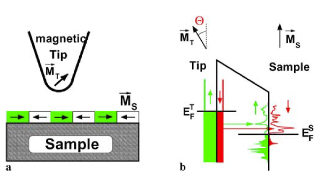
In addition to the above results obtained by SP-STM, also the SPLEEM technique has yielded a number of quantitative studies of DMI in layered systems. In this experimental approach, spin-polarized, low-energy electrons are projected towards the sample surface through an illumination column and reach the sample at normal incidence [238]. A magnetic beam splitter is exploited to separate the incoming electrons from the backscattered ones and a magnified image of the (magnetic) surface is obtained by passing the backscattered beam through an imaging column, similar to that found in electron microscopes (a schematic is shown in Fig.16). This technique is extremely surface-sensitive, since it employs electrons of a few eV energy that do not penetrate more than a few atomic layers, while the lateral resolution is of the order of several nanometers. Therefore, SPLEEM requires in-situ analysis of samples prepared in ultra-high vacuum and it is usually not suitable for samples prepared elsewhere. By a careful comparison of SPLEEM images on films of different thicknesses, the film thickness dependent transition from chiral Néel walls (dominated by the DMI) and non-chiral Bloch walls (dominated by the stray field) can be directly analyzed, so that one can quantify the DMI relying on the fact that the DMI energy and the stray field energy are comparable near the transition thickness. This is because the stray field energy will increase with increasing film thickness whereas the DMI energy is usually independent of the film thickness. Thus, the DMI strength can be quantified by calculating the stray field energy for a wall structure with a given film thickness. This approach has been followed in a number of quantitative studies that are collected in Table13.
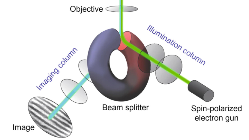
As for Lorentz-TEM microscopy, it was exploited to derive the value of the DMI [99] looking at the mixed Bloch-Néel chiral spin textures in Co/Pd multilayers. An analysis of the observed intensities under varied imaging conditions coupled to corroborative micromagnetic simulations permitted to quantify different magnetic parameters, including the domain wall width, the exchange stiffness and the DMI. Finally, also SEMPA was used to quantify the DMI in thin film systems. For instance, in Corredor et al. [66], using the experimentally determined wall angle and width parameter, a span for the DMI strength of 0.8 meV/Co4.3 meV/Co has been derived, which was in agreement with previous ab initio calculations for this system. Also, in a recent SEMPA study of Fe3GeTe2 films [205] a lower bound of 0.09-0.2 mJ/m2 for the DMI term, films was achieved. A more refined and quantitative result was achieved by [156], studying the domain wall profiles of Co/Ir(111) films as a function of Co thickness via SEMPA. They found that below a cobalt thickness of 8.8 MLs, the magnetic domain walls are purely Néel oriented and show a clockwise sense of rotation. For larger thicknesses the plane of rotation changes and the domain walls show a significant Bloch-like contribution, allowing one to calculate the strength of the Dzyaloshinskii-Moriya interaction (DMI) from energy minimization. In particular, from the angle between the plane of rotation and the domain-wall normal an interfacial DMI parameter 1.07 0.05 pJ/m was determined.
The pioneering approach of these methods was among the first allowing an experimental determination of the DMI and observing directly its influence on the magnetic structure, and therefore the area remained very active and substantial progress towards a quantitative determination of the DMI was achieved (see Table13).
| FM | Bottom NM | Top NM | Sign | Ref | |||
| (meV/atom) | (mJ/m2) | (pJ/m) | |||||
| Fe(1.7ML) | (110)W | 1.2 | +∗ | 202 | |||
| Ni(2ML)/Fe(2.5ML) | (001)Cu | 0.12-0.17 | 0.08-0.12 | - | 52111The values for given in mJ/m2 were kindly provided by the authors of the original paper. In some cases the sign or thickness values were corrected with respect to the original work. | ||
| Ni(2ML)/[Co(1ML)/Ni(2ML)]2 | (111)Pt | 1.05 | 0.44 | - | 5411footnotemark: 1 | ||
| (111)Ir | 0.12 | 0.14 | + | ||||
| (111)Pt/Ir(0.6-3ML) | 0.47-0.12 | 0.28-0.14 | from - to + | ||||
| Ni(15ML)/Fe(3.3ML) | (110)W | 0.53 | 0.32 | + | 5311footnotemark: 1 | ||
| Co(2.4ML) | (0001)Ru | - | 0.05 | 0.18 | + | 29511footnotemark: 1 | |
| Co(3.9ML-8.4ML) | Graphene | 0.11 | 0.25 | - | |||
| Co(0.7nm)[Pd(0.5nm)/Co(0.7nm)]10 | MgO(2nm)/Pt(4nm) | Pt(4nm) | 1.05 | n.a. | 99 | ||
| Co(3.5ML-9.7ML) | (111)Ir | 1.07 | +∗ | 156 | |||
| Co(3ML)/Ni(2ML)/[Co(1ML)/Ni(2ML)]8 | (111)Pd | - | 1.44 | 0.54 | - | 5511footnotemark: 1 | |
| Co(3ML)/Ni(1ML) | (110)W/Pd(2.6ML) | O(0.2ML) | 0.63 | 0.4 | + | ||
| Co(3ML)/Ni(1ML) | (110)W/Pd(2.1ML) | H(0.6ML) | 0.01 | 0.01 | + | 5611footnotemark: 1 |
II.4 Advantages and limitations
In general, methods based on domain walls require an accurate estimation of several magnetic parameters in order to evaluate the interfacial DMI (see. Eq. 2). Among these, the exchange stiffness , which enters both in the expression of the DMI field and in the DW energy, is notoriously difficult to measure for ultrathin films leading to an uncertainty in the quantification of . Han et al. [108] pointed out that in the nucleation method a variation of from 5 to 15 pJ/m for Co results in a 25% difference for obtained using the intermediate value 10 pJ/m. This is not the case for methods based on spin waves (see Sec. III), where is not needed to extract the interfacial DMI. Furthermore, it is worth mentioning that methods that rely on domain walls can be applied to measure only in perpendicularly magnetized materials, while methods based on spin waves (see Sec. III) are able to quantify also for systems with in-plane magnetization. Below we review the main strengths and weaknesses of all methods discussed in this Section.
Both, measurements of current-driven and field-driven DW dynamics in presence of an in-plane magnetic field allow quantifying not only the magnitude of but also its sign, which gives information on the DW chirality. On the other hand, in the creep regime, the dependence of the DW velocity on the in-plane field does not always follow the simple linear dependence when driven by current (see Fig. 4), or the symmetric shape with a well defined minimum in the field-driven case (see Fig. 7). Deviations from these simple theoretical predictions are in fact quite common (see Fig. 8 as an example) and there is no consensus on a general model able to predict and fit all the observed cases. Several models predict that the minimum velocity does not correspond to the DMI field but agreement on its calculation is still missing, and can lead to quite different determination of the value. The main reason is that a full and general microscopic description of the domain wall dynamics is still under investigation. While some systems seem to follow the quenched Edward-Wilkinson equation [4, 103]), there are also experimental evidences that other system are better described by a quenched-KPZ equation [84], having different exponents and critical dynamics. The consequences on the DMI estimation of these two universality classes is still unknown.
Current-driven DW motion is overall a more complex technique to determine the interfacial DMI, both for experimental realization and for the interpretation of the results. A standard lithography process is required to pattern films into wires of appropriate geometry and high in-plane fields, especially for samples with large DMI, need to be applied and properly aligned. Furthermore, the torque generated by large applied currents can also result in a tilt of the DW [87]. Concerning the interpretation of the results, a clear definition of might be hard due to the interplay present in complex systems between different current-induced spin torques (STT, SHE-SOT, iSGE torque), whose collective effect on DW dynamics is still not fully understood.
Field-driven DW motion has the advantage of being a relatively simple method to implement experimentally, as it allows the measurement of interfacial DMI in continuous films, without the need for any lithographic patterning. However, the application of high in-plane fields, particularly for samples with significant DMI, requires a perfect alignment of the in-plane field, with no out-of-plane components. Indeed, in the creep regime any unwanted component of the field perpendicular to the sample plane would influence the DW velocity in an exponential manner (see Eq. 6). Several precautions should be taken into account to achieve an optimal alignment of the in-plane field [125, 169, 261, 44]. A perpendicular stray field component may still arise in MOKE set-ups, due to a cross-talk between in-plane and perpendicular electromagnets or due to not completely non-magnetic objectives, which would alter the field distribution in a way difficult to take into account.
Regarding measurements of DW velocities in the flow regime, here the main difficulty lies in the generation of large and short magnetic field pulses and the measurement of very large velocities. The determination of the DMI constant from the Walker DW velocity (or the saturation velocity after the Walker field) does not need the knowledge of the exchange constant (see Eq. 11), but on the other hand, may not be accessible when hidden in the creep regime.
Among the methods that are based on the DW energy to evaluate the interfacial DMI, imaging the equilibrium stripe domain pattern is particularly straightforward due to its experimental simplicity. Indeed, this method is compatible with any magnetic imaging technique like Kerr microscopy or MFM – which has to be chosen according to the expected domain width – and does not require the application of perpendicular nor in-plane fields. On the other hand, imaging the equilibrium domain configuration does not provide information on the sign of . For multilayer samples with large DMI, small or any situation that yields small values of the left hand side of Eq. 13, high resolution imaging is needed in order to resolve precisely the small domain widths. Experimentally, several problems can emerge that may render it unusable (see Supplementary material of 187): for instance, the demagnetization procedure is unavoidable, since the as-deposited samples may not be in the ground state. In patterned systems, the domain wall width, the domain size and configuration may depend on the geometry, due to confinement and dipolar effects, adding discrepancies with respect to analytical formulations. Other disadvantages include the fact that the simple analytical model to extract may not work for too thick samples which yield neither Néel nor Bloch wall types (hybrid wall with Néel caps and Bloch core), although the DMI is expected to be low in these systems.
From the experimental point of view, the domain widths measured may be different for samples demagnetized with in-plane or out-of-plane fields, up to 20% [172, 71, 162]. For this reason, the in-plane demagnetized configuration is preferred, as it is closer to the parallel stripes described by the analytical theory. In principle, these problems may be solved by using the proper analytical model. The analytical estimations are derived for perfect parallel stripe domains, while the real domain configuration consists of rounded meandering structures. Moreover, refined expressions for the DW energy may yield slightly different values of DMI [177]. This disagreement in the modeling complicates the extraction of DMI and the interpretation of the experimental results.
Similar considerations hold for the method based on magnetic stripe annihilation. Here too, it is only possible to extract information on the absolute value of , and not its sign. From an experimental point of view, the original application of this technique requires the presence of parallel DWs, which may not apply to the case of materials with irregular wall profiles. Those irregular walls can appear for materials that can host skyrmion phases, due to the intrinsic faceting of the DWs in such films. This fact can lead to a deviation from the analytical theory, which was derived for parallel stripe domains. Another drawback is that as the domain walls are closer together the corresponding energy barrier for thermally induced domain wall annihilation is reduced and is also affected by the presence of defects, which can yield an error in the determination of the DMI value.
Since it relies on the nucleation of a reversed domain, the process of bubble nucleation to extract the interfacial DMI is intrinsically a statistical process and several repetitions of the same experiment need to be carried out to achieve a reliable measurement of the nucleation field. In contrast, for instance, imaging the equilibrium domain configuration in a film can automatically provide averaged information of the domain width, from which the DMI is quantified, if a large enough area is imaged. Bubble nucleation experiments can be performed both at the edge of patterned structures, such as nucleation pads or wires, as well as in continuous films. In the former case, the method can be used to determine both the absolute value of as well as its sign. Specifically, the sign of is related to the nucleated bubble position with respect to the direction of the applied in-plane field. On the other hand, bubble nucleation measurements in continuous films provide only the absolute value of .
Concerning the methods based on domain and domain wall imaging, it has been shown on different magnetic systems (see Table13) that SP-STM and SPLEEM (and, to a lesser extent, SEMPA and L-TEM) can be used to achieve a quantitative estimation of the DMI strength, looking at the domain structure or at the transition from Néel to Bloch wall as a function of thickness. One should consider that SP-STM and SPLEEM require a complex apparatus with ultra-high vacuum and in-situ operation, since they are sensitive to the first atomic layers, so that they cannot be employed for samples grown elsewhere and the sample has to be perfectly clean. Use of DFT or Monte Carlo simulations may help in refining the extraction of DMI, but requires a remarkable computational effort. However, the main advantage of these methods is the direct determination of the structure and chirality of the DW.
III Spin wave methods
III.1 Method overview
Since their formation and propagation depend on the magnetic energies present in a material or a thin film, spin waves (SWs) are used as a sensitive tool to extract magnetic properties such as susceptibility, anisotropy, Gilbert damping, exchange stiffness, etc. These properties, together with the geometry of the sample and the excitation, determine the spin wave frequency, linewidth, relative amplitude and attenuation length. The DMI does not only modify the equilibrium magnetic ground state [11] but also the spin wave dynamics [206, 136, 310]. SWs propagating in opposite directions have opposite chirality, so that the DMI contribution to the SW energy may either decrease or increase the SW frequency and results in an intrinsic non-reciprocity of the SW propagation.101010This does not occur for arbitrary directions of DMI vector and spin wave propagation as we will explain further below, and special experimental geometries have to be realized. This is illustrated in Fig. 17. Note that, different from the case of the domain walls analysed in the previous section, where the static magnetization is usually normal to the film plane, here the static component of the magnetization is forced to be in-plane by the external magnetic field. Therefore, in the BLS community it is popular to assume a different reference frame, as we do in this section, where both the applied field and the static magnetization lie along the direction as shown in Fig. 17 while the dynamic component of the magnetization (small blue arrows in Fig. 17) exhibit a chirality that can be either the same or opposite to the DMI-favoured chirality, depending on the propagation direction of SWs. For magnetic films this DMI-induced non reciprocity was investigated the first time by Udvardi and Szunyogh [278] and later a series of theoretical investigations followed [68, 212, 67, 160]. Experimentally, the relatively strong asymmetry in spin wave dispersion is of interest, since the frequency of spin wave spectra can be measured with high accuracy. A pioneering investigation of DMI-induced non-reciprocity in spin wave propagation was performed analyzing SWs with large wavenumber [304] by spin polarized electron loss spectroscopy (SPEELS). Although a high wavenumber is advantageous111111As we will show further below, the DMI -induced frequency shift is linear with wave vector k of the involved spin waves., leading to large DMI-induced frequency changes, the most versatile and exploited technique to determine DMI-related effects on SW propagation is Brillouin light scattering (BLS), which relies on the inelastic scattering of photons by spin waves with micrometric or sub-micrometric wavelength. BLS is becoming more and more popular, thanks to the good compromise between sensitivity to SWs in a wide range of -vectors and relatively simple experimental apparatus. Two techniques that have also been applied to the study of SW propagation are the Time Resolved Magneto-Optical Kerr Effect (TR-MOKE) and Propagating Spin Wave Spectroscopy (PSWS). In the following we first recall some theoretical background about the influence of DMI on SW characteristics and we will review the main results achieved by the four above mentioned experimental techniques, comparing their advantages and limitations.
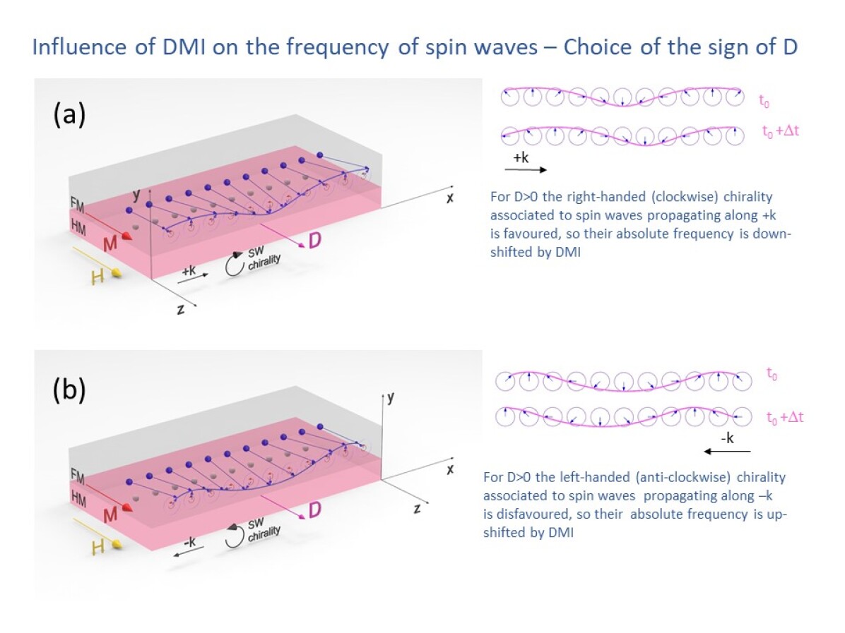
III.2 Theory and models
In the literature we find basically two theoretical approaches to describe spin wave spectra in thin film samples with DMI. One is based on the classical theory of magnetostatic spin waves (see e.g. Gallardo et al. [98]), and this is the approach mainly utilized for analyzing experimental results obtained by BLS, PSWS or TR-MOKE. The other is based on the quantum spin wave theory, which is more suitable for high measurements in ultrathin films as done in SPEELS, where exchange interaction dominates the spin wave dispersion [278, 244, 245]. In most experimental cases, the two formalisms are equivalent and slight differences derive only from the choice of energy terms. Some authors use even a mixed approach calculating the spin wave spectra by a quantization of the linearized Landau-Lifshitz equation [279]. The models used to analyze the experimental results [212] derive typically the dispersion relation and do not consider the specific sensing technique, so that they are applicable to all four techniques presented in the following section.
III.2.1 Quantum spin wave theory
The usual quantum formalism for spin waves uses the Holstein Primakoff method [120] and starts directly from the Schrödinger equation with a Hamiltonian in a crystal lattice of spins that considers the Heisenberg exchange energy at a spin site with the nearest neighbors at position and the Zeeman energy in a magnetic field
| (16) |
where is the exchange constant, the Landé factor, the Bohr magneton. As described in textbooks [265], using the spin raising and lowering operators one can obtain the eigenstates and energies analytically in certain simplified cases (e.g. low temperature approximation) by employing the Holstein-Primakoff transformation and using the Fourier transform of the harmonic oscillator raising and lowering operators as creation and annihilation operators for the quantized spin waves (magnons). For in a cubic lattice of spins with lattice constant , and considering only nearest neighbour interaction, one obtains the known quadratic dispersion relation
| (17) |
As mentioned already in the introduction, in a microscopic approach the DMI is considered a generalized exchange interaction leading to a non-collinear spin configuration described by , where the direction of depends on the crystal symmetry. This leads to an additional term in the Hamiltonian [310, 212]
| (18) |
where is perpendicular to the axis of symmetry breaking. The related term which has to be added in the spin wave dispersion (Eq. 17) is linear in :
| (19) |
A first study of DMI in bulk Ba2CuGe2O7, an antiferromagnet with a weak helimagnetic distortion [310], was performed already in 1999 using the quantum approach, showing low energy spin wave spectra. This approach does not consider the sample geometry but only crystal symmetry, so it is suitable for bulk materials. In the case of ultrathin films, it was shown theoretically about ten years later that the chiral degeneracy of the magnons can be lifted due to the presence of the DMI [278]. The employed method is based on relativistic first principle calculations of the magnetic ground state similar to Bode et al. [29], Ferriani et al. [90], able to identify domain wall chirality. Therefore it was proposed to exploit this spin wave asymmetry for measuring DMI in ultrathin films. Although it was known already for a decade that the DMI stabilizes chiral spin structures in bulk materials with a certain crystal symmetry [70, 31], the work of Udvardi and Szunyogh [278] was stimulated by the discovery of homochirality of domain walls in two monolayers of Fe on W(110) [112, 164].
A quantum approach was also used in Costa et al. [68] where, going back to the microscopic origin of the DMI, the effects of spin-orbit coupling (SOC) on spin wave spectra are studied. It is shown that the DMI leads to a linear term in in the dispersion relation and that the linewidth of spin wave modes is increased by the spin-orbit coupling. The method used here goes beyond the adiabatic approximation and directly operates in the wave vector space, avoiding calculations in real space, taking into account large numbers of neighbor shells. The starting point is the multiband Hubbard model with Hamiltonian [69] where a spin-orbit interaction is added. The spin wave dispersion is then obtained from the dynamic susceptibility. In essence, the quantum approach shows clearly the microscopic origin based on SOC and derives an additional -linear term in the spin wave dispersion relation for certain relative orientations of spin wave propagation and direction of the DMI vector.
III.2.2 Classical spin wave theory
Since in most experimental investigations (as in BLS) the wavelength of the detected SWs are in the range between a few microns and a few hundreds of nanometers, one can ignore the discrete nature of the spins. Therefore, a classical formulation, assuming a continuum medium, is more suitable. Traditionally, spin waves in magnetic thin films are treated as magnetostatic spin waves, neglecting exchange interaction [232]. Considering different geometries and their related boundary conditions one obtains either Forward Volume for perpendicular-to-plane magnetization or Backward Volume and Surface or Damon-Eshbach (DE) Waves for in-plane magnetization. The latter, where the wave vector is perpendicular to the applied static field , is the preferred configuration when exciting spin waves via antennas due to their more efficient transduction. However, as pointed out in several works, for the typical samples with DMI the simple magnetostatic solution is not sufficient and often anisotropy energy or exchange energy have to be considered, as in Gurevich [105], Kalinikos [130], Kalinikos and Slavin [132]. Here the complete problem is solved in the thin film limit for the magnetization including the magnetostatic and dynamic regime using mixed boundary conditions, and going beyond the plane-wave approximation. The exchange term is often neglected when comparing theory to experiments, arguing that the wavenumber obtained in the experimental conditions is low. However, in order to be precise, the spin wave modes obtained in nanostructured films require the complete solution, being in the transition range from magnetostatic to exchange spin waves (dipole-exchange spin waves). One of the critical energy terms is the dipolar field term, which can be obtained from this approach by adding the exchange boundary conditions to the electrodynamics boundary conditions. As mentioned in Moon et al. [212], the dipolar field term contains local and non-local contributions, and can be divided into a stray field term, related to the dipolar interactions between the spins in the SW, and a dipole or magnetostatic field term, related to the demagnetizing field. In most cases, as in Moon et al. [212], the dipolar term for unpinned exchange at the film surface (i.e. at the FM film surface) is applied [131]. However, Kostylev [160] points out that the DMI pins the circular components of the magnetization at the surface (interface) of the magnetic film and mixed boundary conditions have to be used, which require a numerical solution.
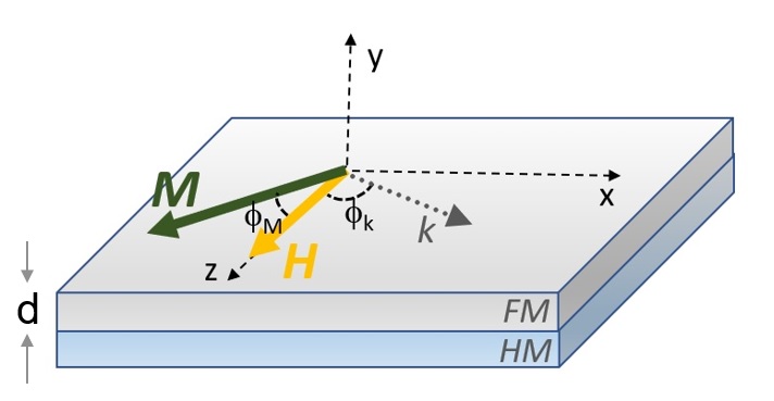
Considering a sample geometry as shown in Fig. 17, (static component of the magnetization aligned along the z direction, i.e. parallel to the applied field ) the dispersion relation for small amplitude spin waves is derived from the linearized Landau-Lifshitz (LL) equation
| (20) |
The vector has to be decomposed in one large static component, of modulus directed along the -axis and two small dynamic components that describe the precession around the equilibrium direction: with and ,, are the unitary vectors of the reference frame, chosen such that the -axis is perpendicular to the sample plane, according to Fig. 17. The effective field to be considered in the LL equation consists of different contributions, reflecting the different energy terms:
| (21) |
where is the exchange constant. In case of unpinned exchange boundary conditions the dipolar field for a thin film can be written as [5, 131]:
| (22) | |||
| (23) |
that, in the case of ultrathin films with thickness , where , reduces to when performing a series expansion of the exponential function. The anisotropy field, written for the case of a uniaxial perpendicular anisotropy constant out-of-plane, is
The correct expression for the DMI field in the continuum theory is not that straightforward to obtain as it depends on the crystal symmetry considered. For bulk, the first approach from a spin to a continuum model was performed by Dzyaloshinskii himself [85], calculating a thermodynamic potential for certain crystal symmetry classes. This approach was used later by Bak and Jensen [11] for MnSi and FeGe, and by Bogdanov and Hubert [30], Bogdanov and Rößler [31] using the Lifshitz invariants , where the -th component of is . The DMI energy can be described as a combination of Lifshitz invariants, depending on the crystal symmetry [70, 67]. For certain symmetry classes, as the rotational tetrahedral T121212Schoenflies notation (e.g. MnSi), the energy density due to DMI is a combination of Lifshitz invariants with a single coefficient . Only in these cases the DMI strength is sufficiently described by a scalar. Another example is the cyclic class 1212footnotemark: 12. Its Lifshitz invariants are a suitable choice for planar systems (bilayers) with perpendicular anisotropy, where symmetry breaking occurs only along the perpendicular axis and only gradients in plane contribute to the DMI induced chirality [33, 31]. For a planar geometry in the plane with perpendicular anisotropy along , the DMI energy can than be described by
| (24) |
With the DMI field can then be obtained as
| (25) |
The dispersion relation is then given by
| (26) |
that is valid also for values of different from , as shown in Fig. 18. Moreover, it can be shown that the general expression of for an interfacial DMI is given by [98].:
| (27) |
where the angles are defined in Fig. 18. This means that, similar to the results of the quantum approach reported in the previous paragraph, the DMI leads to a shift of the dispersion relation, linear in , and depending on the sign of the wave vector, i.e. a frequency non-reciprocity due to DMI (see Fig. 19). This non reciprocity depends on the directions of both the sample magnetization and the spin wave propagation direction and is absent for , i.e. the condition for ferromagnetic resonance (FMR). In this respect, already in Cortés-Ortuño and Landeros [67] it was suggested to use BLS measurements for determining the DMI constant, pointing out that the largest effect can be observed applying a sufficiently large external field H, so that the magnetization lies in-plane (), using the Damon-Eshbach (DE) geometry ().
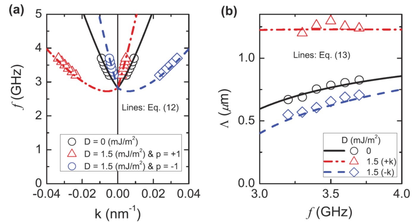
It is worth noting that the above dispersion relation is valid up to a certain threshold of the DMI strenght, above which the dispersion relation becomes zero and the ground state is not uniform but rather chiral and the theory may not be applicable. By numerical calculations it is shown that the asymmetry does not only regard frequency but also amplitude and attenuation length [160, 159].
Let us also notice that the above description is valid only for a film consisting of a single monolayer. An attempt to take the finite film thickness correctly into account by using mixed exchange boundary conditions at the surface is shown in Kostylev [160]131313Note: The DMI constant in Kostylev [160] is defined as the DMI constant in the first atomic layer and therefore is defined as , where is the lattice constant.. The resulting boundary conditions then are similar, but not equal, to the ones derived for a uniaxial surface anisotropy [260]. Different surface anisotropies at both interfaces of the magnetic film result in an intrinsic non reciprocity of DE spin waves [117]. In this case the two contributions are difficult to be distinguished. In fact, already in Crépieux and Lacroix [70], the presence of DMI can be interpreted as a contribution to the surface anisotropy. In order to analyze the different contributions in a more rigorous way, film thickness dependencies have to be studied, as discussed in Gladii et al. [102], Lucassen et al. [188].
In summary we want to point out that the complete solution in the continuum theory for the bilayer system is not trivial, requiring assumptions concerning the boundary conditions. Especially, care has to be taken if one wants to take all contributions to the spin wave dispersion non-reciprocity (such as surface anisotropies) into account correctly. However, in most cases the theory required for modeling experimental results is simplified by the fact that by subtraction (as explained in the following sections) the DMI related term in the spin wave dispersion relation is directly determined.
III.3 Experimental results
III.3.1 Brillouin light scattering
The most popular and widely employed technique for the measurement of the DMI constant from the non-reciprocal spin wave propagation is Brillouin light scattering (BLS) [46]. As shown in Tables 14, 15, 16 and 17, more than forty papers have been published during the last five years, reporting the value of the DMI constant in samples where a FM material (usually Co or CoFeB) is in contact with a HM material (such as Pt, W, Ta, etc.). One of the first BLS experimental works reporting values of the DMI constant determined by BLS was done on Co/Ni multilayers [74, 73, 307]. In the same year a series of publications of DMI measurements by BLS on Py, Co and CoFeB followed [280, 266, 222, 20, 61, 142] and the research continues to be very active.
BLS is a classical tool to study spin wave dispersion in general and non-reciprocity in particular. As sketched in Fig. 20 in a BLS experiment a monochromatic light beam is focused on the surface of the specimen under investigation by an objective lens and the light that is back-scattered within a solid angle is collected by the same lens and analysed in frequency by a high-resolution spectrometer, usually a Sandercock-type, multipass tandem Fabry-Perot interferometer [211]. The physical mechanism of BLS relies on the inelastic scattering of photons by spin waves that are naturally present within the medium under investigation, thanks to either the creation (Stokes process) or the annihilation (anti-Stokes process) of a magnon. This implies that a red-shift or a blue-shift is observed in the scattered light with respect to the incident beam. In wave vector space, magnons experiencing Stokes or anti-Stokes scattering processes correspond to either a positive or a negative wave vector. As a consequence, the non-reciprocity caused by the presence of a DMI interaction leads to an asymmetry in frequency shift of the peaks corresponding to the Stokes or the anti-Stokes process, as anticipated in the previous paragraph (see Fig. 20). A rather wide range of vectors is available, up to about 2.2 rad/cm. The specific value of can be varied easily by changing the angle of the incident beam of light, while reversing the applied magnetic field permits to cross-check for the sign of the DMI constant. The frequency resolution is limited by the instrumental characteristics to about 0.1 GHz, because the finesse of the Fabry-Perot interferometer (ratio between the free spectral range and the pass-band window) has an upper limit of about 100 [46]. This implies a lower limit for the minimum values of the DMI constant that can be measured by this technique. One should also consider that usually several tens of mW of light are focused on the measurement spot, so that the real temperature141414Note: The real temperature depends on the thermal properties of the material under investigation (including the substrate material), as well as on the numerical aperture of the exploited lens (that determines the size of the focused light spot). of the probed sample region may be lifted above room temperature and this can have an influence on the values of the measured magnetic parameters, including . Here we adopt the reference frame presented in Figs. 17 and 20, where the -axis is aligned with the static magnetization, the -axis coincides with the propagation direction of SWs and the film normal (- axis) is oriented upward with respect to the free surface of the FM film. With such a choice, the frequency shift of the BLS peaks is
| (28) |
For the case of a FM/HM bilayer, as sketched in Fig. 20, a negative (positive) value of , i.e. of , indicates that a left (right)-handed chirality is favoured by the DMI. This means that in presence of a positive (negative) value of , in the measured BLS spectra the absolute frequency of the anti-Stokes (Stokes) peak is larger (lower) than that of the Stokes (anti-Stokes) one, and as a consequence assumes positive (negative) values, as illustrated in the lower panel of Fig. 20. Please note that if the direction of the applied magnetic field is reversed, changes sign due to the reversal of the SW chirality.
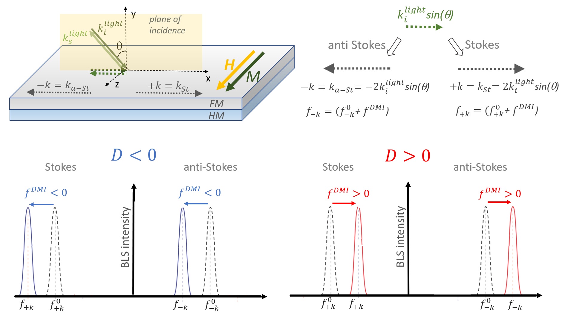
A comparison of the value and the sign of the DMI constant measured using BLS for Co, CoFeB, and a collection of different magnetic materials are reported in Tables 14, 15, 16 and 17, respectively. When the values were not explicitly given in the original manuscript, we have calculated or extracted them from the figures and reported them in italic. Note that the signs in the Tables are consistent with the convention of axes, field, , vector and frequency difference as previously described in Figs. 17 and 20. If the authors in the original manuscript have used a different coordinate system and/or method of calculating the frequency asymmetry we recalculated the sign according to our convention.
Many papers discuss the dependence of the DMI constant as a function of the ferromagnetic layer thickness [266, 20, 49, 141] and possible correlation with surface anisotropy [266] or Heisenberg exchange [222]. Theoretically, a dependence of the DMI constant is predicted [160], as is the case for all interface phenomena, and this makes it difficult to distinguish between the different phenomena. Sometimes a change in slope of the DMI constant versus is observed [61, 148, 17, 18]. Belmeguenai et al. [17] discuss different origins of this change. The first is a coherent-incoherent growth mechanism transition at a certain thickness accompanied by magnetoelastic anisotropy changes. Others are changes in surface roughness which are causing in-plane demagnetizing magnetic fields. Another is interdiffusion and mixing at the interfaces, which reduces the interface anisotropy. According to the experimental results the authors conclude that the first hypothesis is the most probable.
Similarly, the dependence of the DMI on the heavy metal thickness has been studied for both Co [151] and CoFeB [59, 268] films in contact with a Pt layer. For both systems the DMI intensity was found to increase with the Pt thickness, , reaching a saturation value when approaches the Pt spin diffusion length (about 2 nm). This behaviour has been explained by analytical calculations assuming that several Pt atoms, belonging to different layers in the heavy metal, can contribute to the strength of the interfacial DMI [268]. On the contrary, in Ma et al. [191], the DMI strength in the IrMn/CoFeB system was observed to increase even for IrMn layers thicker than the IrMn spin diffusion length (about 0.7 nm). The authors claim that this DMI enhancement can be ascribed to the reduction of the thermal fluctuations of the antiferromagnetic (AFM) spin arrangement when the IrMn thickness increases, suggesting a different microscopic origin with respect to HM/FM systems.
The sign of the DMI constant was investigated for several material combinations by changing both the stacking order and the multilayer composition [60]. In systems with a Pt (W) underlayer, negative (positive) values of the DMI constant have been found with a quite overall agreement, indicating that a left-handed (right-handed) chirality is favored. In agreement with the theoretical calculations, it has also been observed that the sign of DMI is reversed when the stacking order is inverted, while its value becomes negligible in symmetric structures where a FM film is sandwiched between two identical HM layers. On the contrary, the DMI sign induced by other materials, such as Ir or IrMn, is still the subject of controversial debate in the literature (see for instance [192, 191, 17]). However, most experimental works contradict the theoretical prediction of Ir leading to opposite DMI sign with respect to Pt [296]. Recently, the influence of electric fields on the DMI strength has been investigated in Ta/FeCoB/TaOx trilayer [264]. A strong variation of the value has been observed and attributed to the dependence of the DMI at the CoFeB/Oxide interface on its oxydation state, that can be electrically tuned. Among the Co articles, 139 investigate the effect of exchange bias with an antiferromagnetic (AFM) overlayer on Co and confirm that DMI is not influenced by exchange bias or the AFM spin order. Finally, the sinusoidal dependence of the frequency non-reciprocity as a function of the angle between the sample magnetization and the SW wave vector, theoretically predicted by Cortés-Ortuño and Landeros [67], has been experimentally verified for different multilayer structures [17, 141, 60, 268, 307].
Let us notice that several studies were able to correlate the presence of a sizeable DMI not only to the frequency position of the BLS peaks but also to their linewidth, i.e. to the damping that affects spin waves. Already Di et al. [74] studied the interfacial DMI in an in-plane anisotropic Pt(4)/Co(1.6 nm)/Ni(1.6 nm) film by Brillouin spectroscopy, showing that the measured linewidths of counterpropagating magnons are different, with the difference being more pronounced for larger wave vectors. This could be ascribed to a DMI-induced term that is antisymmetric in the wave vector. Moreover analytical calculations showed that, due to the existence of the DMI, the magnon linewidth is no longer a monotonic function of frequency. In Chaurasiya et al. [49], asymmetry in the peak frequency, peak intensity and magnon lifetime were observed in W/CoFeB/SiO2. Also in this case the linewidth for spin-wave propagating in direction is smaller than the same for spin-wave propagating in direction, indicating different lifetimes of magnon propagating in opposite directions, induced by DMI. More recently, a clear correlation between the DMI strength and the SW damping were demonstrated by combined FMR and BLS investigation in different kind of systems, such as [Pt(1.5)/Co()/W(1.5)]xN multilayers [21], Py(5)/ Cu1-xPtx bilayers [38] and He+ irradiated Ta/CoFeB/MgO films [77].
Very recently, several works reported that a sizeable interfacial DMI can also arise at the interface between an oxide layer and a ferromagnetic one [6, 221, 181, 155]. Nembach et al. [221] studied the interfacial DMI in Cu(3)/Co90Fe10(1.5)/Ta()/Oxide/Ta(3) systems, where the oxide layer was prepared by in-situ sample oxidation. Changing the Ta thickness, , an oxide layer of CoFeOx and/or TaOx was obtained following the sample exposure to oxygen. The authors found that both the magnitude and sign of the interfacial DMI can be tuned by varying the thickness and the composition of the oxide layer, due to the changes of the electronic structure at the interface, induced by the oxidation process. Moreover, Lin et al. [181] showed that in the BaTiO3 (BTO)/CoFeB system the DMI strength is strongly affected by the termination of the oxide layer (TiO2 vs BaO). In particular, a higher value of the DMI constant was found for a TiO2-BTO substrate, and this finding was attributed by first principle calculations to the different electronic states around the Fermi level at the oxide/FM interfaces.
In summary, BLS has rapidly become the most used technique for measuring DMI using spin waves. A reasonable complexity of the experimental setup and a high accuracy in the determination of the spin wave dispersion, together with the fact that no external excitation is needed for this technique, which relies on thermal excitation, contribute to the success and spreading of this technique.
| FM | Bottom NM | Top NM | Sign | Ref | ||
| (nm) | (nm) | (nm) | (mJ/m2) | (pJ/m) | ||
| Co(0.6-1.2) | Ta(3)/Pt(3) | AlOx/(2)Pt(3) | 2.7-1.6 | 1.6-1.9 | - | 20 |
| Co(1-2) | Pt(4) | AlOx(2) | 1.2-0.9 | 1.2-1.8 | n.a. | 61 |
| Co(1) | Pt(5) | GdOx(2-5)/Al(2) | 1.6 | 1.6 | - | 280 |
| Co(1-1.7) | Pt(4) | AlOx(2) | 1.2-0.8 | 1.2-1.4 | -∗ | 150 |
| Co(1.3-1.8) | Ta(4)/Pt(4) | 1.6-1.3 | 2.1-2.3 | -∗ | ||
| Co(1.06) | Ta(3)/Pt(3) | MgO(2)/Ta(2) | 2.05 | 2.17 | - | 37 |
| Co(1.3-2.9) | Ta(4)/Ir(4) | AlOx(2) | 0.7-0.35 | 0.9-1 | n.a. | 152 |
| Co(2) | Ta(4) | Pt(4) | 0.7 | 1.4 | + | 60 |
| Pt(4) | Ta(4) | 0.92 | 1.84 | - | ||
| Co(1.6) | Ta(4)/Pt(0.8) | AlOx(2)/Pt(1) | 0.43 | 0.7 | - | 151 |
| Ta(4)/Pt(4.8) | 1.57 | 2.51 | - | |||
| Co(2.5) | Pt(5.4) | Au (2.5)/Pt(2.6) | 0.60 | 1.51 | - | 239 |
| Ir(2.5)/Pt(2.6) | 0.60 | 1.51 | - | |||
| Co(1) | Ta(5) | MgO(2)/Ta(2) | 0.08 | 0.08 | + | 192 |
| W(5) | 0.11 | 0.11 | + | |||
| Ir(5) | 0.34 | 0.34 | - | |||
| Pt(5) | 1.59 | 1.59 | - | |||
| Au(5) | 0.22 | 0.22 | - | |||
| Co(3) | MgO(2)/Pt(6) | Ru(3) | 0.43111The sample is a stripe sample with stripe width 300 nm and spacing 100 nm | 1.311footnotemark: 1 | - | 39 |
| 0.33222Stripe width: 100 nm, spacing 100 nm | 122footnotemark: 2 | - | ||||
| Co(1) | Ta(5)/Pt(2) | Ir20Mn80(1.1) | 1.14 | 1.14 | - | 139 |
| Ir20Mn80(1.7) | 1.14 | 1.14 | - | |||
| Ir20Mn80(2.4) | 1.22 | 1.22 | - | |||
| Ir20Mn80(5) | 1.11 | 1.11 | - | |||
| Co(0.6) | Ta(5)/Pt(2) | Fe50Mn50(1) | 1.5 | 1.35333For calculation, the authors have added a monolayer of Fe from Co/FeMn interface to the effective thickness of the FM layer. | - | 139 |
| Fe50Mn50(2.6) | 1.44 | 1.333footnotemark: 3 | - | |||
| [Co(0.2)/Ni(0.6)]2/Co(0.2) | Pt(1.2) | Ta(0.8)/TaN(6) | 0.49 | 0.88 | - | 167 |
| Ir(1.2) | 0.05 | 0.09 | - | |||
| Pt0.4Ir0.6(1.2) | 0.19 | 0.34 | - | |||
| Pt0.6Ir0.4(1.2) | 0.24 | 0.43 | - |
| FM | Bottom NM | Top NM | Sign | Ref | ||
| (nm) | (nm) | (nm) | (mJ/m2) | (pJ/m) | ||
| Co(1-2) | Ta(3)/Pt(3) | Ir(3) | 0.8 – 0.3 | 0.8 | - | 19 |
| Cu(3) | 0.9 – 0.4 | 1.05 | - | |||
| MgO(1) | 0.9 – 0.4 | 0.95 | - | |||
| Pt(3) | 0 | 0 | ||||
| [Pt(1.5)/Co(1-2)/W(1.5)]x1 | 0.2 - 0.3 | 0.55 | - | 21 | ||
| [Pt(1.5)/Co(1-2)/W(1.5)]x3 | 1.1 - 0.6 | 0.85 | - | |||
| [Pt(1.5)/Co(1-2)/W(1.5)]x7 | 1.2 - 0.6 | 0.90 | - | |||
| Co(0.6) | Pt(3) | HfO2(3) | 0.9 | 0.54 | - | 76 |
| Co(0.9) | Ta(5)/Pt(1.5) | Ti(2.5)/Pt(2.5) | 1.42 | 1.28 | n.a. | 143 |
| Cu(2.5)/Pt(2.5) | 0.87 | 0.78 | n.a. | |||
| W(2.5)/Pt(2.5) | 1.25 | 1.13 | n.a. | |||
| Ta(2.5)/Pt(2.5) | 0.99 | 0.89 | n.a. | |||
| Al(2.5)/Pt(2.5) | 0.92 | 0.83 | n.a. | |||
| Pt(2.5)/Pt(2.5) | 0.02 | 0.02 | n.a. | |||
| Co(1.4) | Ta(5)/Pt(5) | MgO(2)/Ta(3) | 1.20 | 1.68 | n.a. | 155 |
| Cu(2)/Ta(3) | 1.05 | 1.47 | n.a. | |||
| Co(0.8) | Ta(2)/Pt(2.2) | Ir(0-2)/Ta(4) | 1.8 - 0.88 | 1.64 - 0.7 | -* | 254 |
| [Pt(3)/Co(1.1)/Ta(4)]x12 | 0.78 | 0.86 | - | 243 | ||
| Co(1.2) | Ta(2.5)/Pt(0.4-2.2)444On a glass substrate | Pt(2) | 0.27 - 0.42 | 0.32 - 0.5 | + | 106 |
| Co(0.8-2.5) | Ta(3)/Pt(3) | Ir(3) | 0.95 - 0.3 | 0.76 | - | 23 |
| Co(0.9-2.5) | Ta(3)/Pt(3)555Annealed at 300oC | Ir(3) | 0.6 - 0.2 | 0.53 | - | |
| Co(1.1-3.1) | Ta(3)/Ir(3)55footnotemark: 5 | Pt(3) | 0.88 - 0.32 | 1.05 | + | |
| Co(1-2.6) | Ta(3)/Ir(3)666As grown | Pt(3) | 0.8 - 0.3 | 0.77 | + | |
| Co(0.8-2.5) | Ta(3)/Pt(3)55footnotemark: 5 | Cu(3) | 1.31 - 0.42 | 1.05 | - | |
| Co(1-2.2) | Ta(3)/Pt(3)55footnotemark: 5 | MgO(1) | 1 - 0.5 | 0.95 | - | |
| Co(1.5-2.1) | Ta(3)/Pt(3)66footnotemark: 6 | MgO(1) | 0.8 - 0.6 | 1.17 | - | |
| Co(1.2-10) | Pt(3) | TaOx(0.8)/Al(0.5) | 1 - 0.15 | 1.25777This value was extracted by the authors from a fit of the experimental data of all samples with various Co thicknesses. | - | 24 |
| Co(1.2) | Pt(3) | TaOx(0.7-0.9)/Al(0.5) | 1.2 - 1.5 | 1.44 - 1.8 | - | |
| Co(1.2) | Pt(3)/Cu(0-2.4) | TaOx(0.8)/Al(0.5) | 1.3 - 0 | 1.56 - 0 | - | |
| Co(0.7) | Pt(5) | NixOy(15) | 1.75777Sample deposited with Ar pressure of 0.13 Pa | 1.3 | - | 157 |
| [W(1)/Co(0.6)/Pt(1)]x10 | 2.65 | 1.83 | + | 126 | ||
| [W(1)/Co(0.6)/Pt(1)]x20 | 2.49 | 1.72 | + | |||
| FM | Bottom NM | Top NM | Sign | Ref | ||
| (nm) | (nm) | (nm) | (mJ/m2) | (pJ/m) | ||
| Co48Fe32B20(1.6-3) | Pt(4) | AlOx(2) | 0.8-0.4 | 1.2-1.3 | n.a. | 61 |
| Co40Fe40B20(0.8) | MgO(2)/Pt(2) | MgO(2)/SiO2(3) | 1 | 0.8 | - | 73 |
| Co20Fe60B20(0.85, 1, 1.5, 2, 3) | W(2) | SiO2(2) | 0.25-0.08 | 0.21-0.24 | n.a. | 49 |
| Co20Fe60B20(1) | W(2) | MgO(1)/Ta(1) | 0.25 | 0.25 | +* | 261 |
| W(3) | 0.27 | 0.27 | +* | |||
| Ta48N52(1) | 0.31 | 0.31 | +* | |||
| Hf(1) | 0.15 | 0.15 | +* | |||
| Co20Fe60B20(1) | Ta(5) | Pt(0.12-0.27)/MgO(2) | 0.07-0.015 | 0.07-0.015 | + | 190 |
| Co20Fe60B20(2) | Ir22Mn78(1-7.5) | MgO(2)/Ta(2) | 0.02-0.13 | 0.04-0.26 | - | 191 |
| Co20Fe60B20(0.8-2) | Ir22Mn78(5) | 0.15-0.07 | 0.12-0.14 | - | ||
| Co20Fe60B20(1.2) | Ir(5) | 0.17 | 0.2 | + | ||
| Co40Fe40B20(2) | Si/SiO2 | Pt(2)/Cu(3) | 0.45111for 2nm | 0.9 | + | 268 |
| Co40Fe40B20(2) | Pt(4) | Ta(4) | 0.51 | 1.02 | - | 60 |
| Ta(4) | Pt(4) | 0.43 | 0.86 | + | ||
| Ta(4) | Ta(4) | 0.15 | 0.3 | - | ||
| Pt(4) | Pt(4) | 0.01 | 0.02 | - | ||
| Co20Fe60B20(1.12) | Ta(3)/Pt(3) | Ru(0.8)/Ta(3) | 0.84 | 0.94 | - | 16 |
| Pt(3)/Ru(0.8) | MgO(1)/Ta(3) | 0.3 | 0.37 | - | ||
| Co20Fe60B20(1) | Ta(5) | MgO(2)/Ta(2) | 0.04 | 0.04 | + | 192 |
| W(5) | 0.07 | 0.07 | + | |||
| Ir(5) | 0.21 | 0.21 | + | |||
| Pt(5) | 0.97 | 0.97 | - | |||
| Au(5) | 0.17 | 0.17 | - | |||
| [Pt(5)/Co20Fe60B20(1)/Ti(1)]x1 | Ti(5) | Pt(5) | 0.81 | 0.81 | n.a. | 133 |
| [Pt(5)/Co20Fe60B20(1)/Ti(1)]x10 | 0.79 | 0.79 | n.a. | |||
| [Pt(5)/Co20Fe60B20(1)/Ti(1)]x15 | 0.67 | 0.67 | n.a. | |||
| [Pt(5)/Co20Fe60B20(1)/Ti(1)]x60 | 0.71 | 0.71 | n.a. | |||
| CoFeB(1) | Ta(5)/Pt(0.7-4) | MgO(1)/Ta(1) | 0- 0.87 | 0- 0.87 | - | 59 |
| Co40Fe40B20(0.9) | W(1-13) | MgO(1)/Ta(2) | 0.25-0.7 | 0.23-0.63 | n.a. | 148 |
| Co20Fe60B20(0.9) | Ta(3) | TaOx(1) | 0.08 | 0.05∗ | + | 264 |
| Co20Fe60B20(1.5) | Ta(1) | Cu(0-2.4)/Pt(4) | 0.52 - 0.14 | 0.78 - 0.21 | + | 22 |
| Ta(0-2.4)/Pt(4) | 0.52 - 0 | 0.78 - 0 | + | |||
| MgO(0-1.8)/Pt(4) | 0.55 - 0 | 0.78 - 0 | + | |||
| Co20Fe60B20(1.5-6) | Pt(4) | 0.7 - 0.2 | 1.25222 is obtained from the linear fit of versus for 1.5 nm ( is the FM thickness) | + | ||
| Co20Fe60B20(2) | TiO2-BTO | Pt(4) | 0.45 | 0.9 | + | 181 |
| BaO-BTO | Pt(4) | 0.56 | 1.12 | + |
| FM | Bottom NM | Top NM | Sign | Ref | ||
| (nm) | (nm) | (nm) | (mJ/m2) | (pJ/m) | ||
| Co(1.6)/Ni(1.6) | Pt(4) | MgO(2)/SiO2(3) | 0.44 | 1.4 | - | 74 |
| Ni80Fe20(4) | Si substrate | Pt(6) | 0.056151515This value was calculated according to the definition of used in this paper from the original value by , where =0.248nm is the lattice constant of Py | 0.34 | + | 266 |
| Co(1.6)/Ni(1.6) | MgO(2)/Pt(4) | MgO(2)/SiO2(3) | 0.44 | 1.4 | - | 307 |
| Ni80Fe20(1-13) | Ta(3)/Pt(6) | SiN | 0.15-0.025 | 0.15 - 0.33 | - | 222 |
| Co2FeAl(0.9-1.8) | Ta(2)/Ir(4) | Ti(2) | 0.5 - 0.3 | 0.37∗ | - | 17 |
| Fe(3) | SiO2 | Pt(4) | 0.22 | 0.67 | + | 309 |
| MgO(5) | 0.35 | 1.05 | + | |||
| Py(5) | Cu1-xPtx(6)161616=0,6.6,28,45,75,100 % | 0 - 0.05 | 0 - 0.27 | + | 19 | |
| Co90Fe10(1)/oxide171717Oxidation: 0-1000 s at 99 % Ar and 1 % O2 | Ta(3)/Pt(6) | Cu(3)/Ta(2) | 1.29-1.65 | 2.52 | - | 221 |
| Ta(3)/Cu(6) | -0.02-0.26 | 0.4181818The value refers to the longest oxidation of 1000 s | - | |||
| YIG(10) | GGG substrate | 0.01 | 0.1 | n.a. | 285 | |
| [Py(1)/Pt(1)]10 | Ta(5)/Pt(6) | Au(3) | 0.032 | 0.032 | - | 2 |
| Fe(3) | SiO2(4) | Pt(4) | 0.25 | 0.75 | + | 308 |
| SiO2(4)/Pt(4) | SiO2(4) | 0.33 | 1 | - | ||
| SiO2(4)/Au(4) | SiO2(4) | 0.07 | 0.21 | + | ||
| SiO2(4) | Au(4) | 0.07 | 0.21 | + | ||
| SiO2(4)/Au(4) | Pt(4) | 0.4 | 1.2 | + | ||
| SiO2(4)/Pt(4) | Au(4) | 0.17 | 0.51 | - |
III.3.2 Time resolved magneto optical imaging
Time resolved magneto-optical Kerr microscopy (TR-MOKE) allows detecting propagating spin waves in real space and as a function of time enabling the determination of the spin wave -vector and decay. TR-MOKE was employed by Körner et al. [159] in order to determine DMI in a Pt/Co/Py/MgO multilayer. For imaging spatially and time dependent spin wave signals a focused laser pulse (spot size 300 nm) of 400 nm and pulse length 200 fs (repetition rate 80 MHz) is used. The laser pulses are phase locked to a microwave generator connected to a coplanar wave guide (CPW or microwave antenna) deposited on top of the thin film sample as shown in Fig. 21. The excited -vectors are in the range of 2-10 m-1. The dynamic out-of-plane magnetization is detected via MOKE along the direction normal to the CPW up to a distance of 5 m from the center of the CPW. The spin wave dispersion is determined by using the expression given in Moon et al. [213]. The Co film is 0.4 nm thick and has a perpendicular magnetic anisotropy (PMA). During the measurement it is magnetized in plane parallel to the CPW. Due to its low damping, the 5 nm Py film on top of Co facilitates the SW propagation. Damon-Eshbach modes are detected at various distances from the CPW. Therefore it is possible to detect with this technique not only frequency and amplitude non reciprocity, but also a non reciprocity in attenuation length of the spin waves, as predicted by theory.
Apart from the necessity of a pulsed laser system, the complexity of a TR-MOKE experiment is comparable to BLS, as far as the optical signal acquisition is concerned. However, SWs need to be excited by a CPW which has to be prepared by lithography directly on top of the sample. The -vectors that can be excited are limited by the CPW geometry. Broadband excitation can be obtained by a single line (as e.g. in Ciubotaru et al. [63]) with the drawback that the amplitude is reduced with respect to a monochromatic excitation. Since high values are preferable, the CPW lines have to be rather narrow (1 m) which requires electron beam lithography (EBL). Boundary conditions for the generation of plane waves have to be taken into account and it is preferable to have stripes of magnetic material (see supplemental material of Chauleau et al. [48]). The Gilbert damping limits strongly the technique [14], since the attenuation length with large damping parameter becomes too small for the SW to be detectable, which is a significant drawback with respect to BLS.
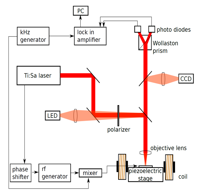
III.3.3 Propagating spin wave spectroscopy
Propagating spin wave spectroscopy (PSWS) (see Fig. 22) is a tool to characterize spin waves excited in magnetic thin films by measuring the dispersion relation and group velocity all-electrically using a standard high frequency (HF) instrument, a Vector Network Analyzer (VNA) [247, 265, 10]. In the field of magnonics it was widely applied (e.g. Neusser et al. [223]). As depicted in Fig.22, the VNA emits HF signals in antenna 1 and receives the transmitted and reflected signals in antenna 2 and 1, respectively (and vice versa). The mutual inductance spectra are obtained from the transmission and reflection coefficients. The inductance spectra show a shift in frequency in presence of DMI (see Fig.23) from which is directly obtained through Eq.27. Currently there are only a few experimental works published applying PSWS to measure the DMI constant.
In Lee et al. [171], one of the first that applied PSWS, spin waves are excited by a meander shaped CPW (similar to Vlaminck and Bailleul [283]), and detected in a second CPW at a certain distance, thus measuring the spin wave dispersion and group velocity by a VNA [9]. The measured magnetic multilayers are Pt/Co/MgO, MgO/Co/Pt and MgO/Co/MgO in order to compare samples with positive and negative DMI constant with one with vanishing DMI. The films were patterned into 8 m wide stripes and a 40 nm thick AlOx layer for electric insulation was deposited on top. The CPW consists of Ti(5)/Au(150) and was realized with a primary spatial period of 800 nm (=7.85 m-1) and subsidiary spatial period of 2250 nm ( 2.8 m-1). The Co thickness was changed from 14 nm to 20 nm. The DMI constant is considered here to be a pure interface effect with a characteristic length 0.25 nm, so that the interfacial DMI is calculated to be . Assuming that remains constant the authors obtain a value 1.8 pJ/m2 for a Co thickness of 2 nm.
In Kasukawa et al. [135], a similar film Ta(2)/Pt(3)/Co(20)/MgO(2) was investigated for electric field effects. Modulations of spin wave frequency were obtained by the gate electric field and the electric field dependence of the DMI was calculated to be 20.93 fJ/Vm. The interfacial DMI was obtained at zero electric field and calculated to be 0.450.15 mJ/m2. The value calculated for , as defined in this paper, is very high compared with other techniques. The authors reason that the measured frequency shifts are not caused by the effects of different interfacial anisotropies at the Pt/Co and MgO/Co interface, since no magnetic field dependence was observed. Therefore, they attribute the whole to the interfacial DMI. However, it appears that the measured value is overestimated in this way.
Lucassen et al. [188] investigate Ta(4)/X(4)/Co(d)/Y(3)/Pt(2) stacks with 4-26 nm and (X,Y)=(Pt, Ir),(Ir, Pt) by meander type CPWs with wave vectors 4, 5.5, 7, 8.5, 10 m-1. Changing the Co thickness in such a wide range leads to a gradual transition between different Co phases and therefore a change in volume anisotropy in the different samples has to be considered. A detailed analysis of the frequency non-reciprocity due to DMI considering surface anisotropy and changes in volume anisotropy is performed. Also Gladii et al. [102, 101] (see Fig. 24) performed an analysis of the influence of a difference in surface (interface) anisotropy on both sides of a Permalloy film on the SW dispersion. In Gladii et al. [102] the frequency non reciprocity due to different surface anisotropies was calculated revisiting the approach of Kalinikos and Slavin [132]. The important result of the paper is that the frequency non reciprocity due to a difference in surface anisotropies scales as , where is the thickness of the FM film, while the contribution due to DMI scales with . In this approach, the exchange spin waves play an important role and a purely magnetostatic approach would lead to unrealistic modal profiles. In Gladii et al. [101] additionally the spin wave relaxation rate was measured using two CPWs as emitter and detector at different distance. An injected DC current in the Pt layer induced STT via the spin Hall effect and linearly altered the spin wave relaxation time. From this it was possible to obtain additional information such as the spin Hall conductivity.
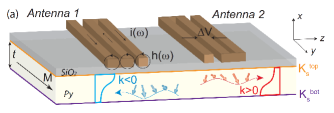
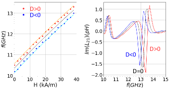
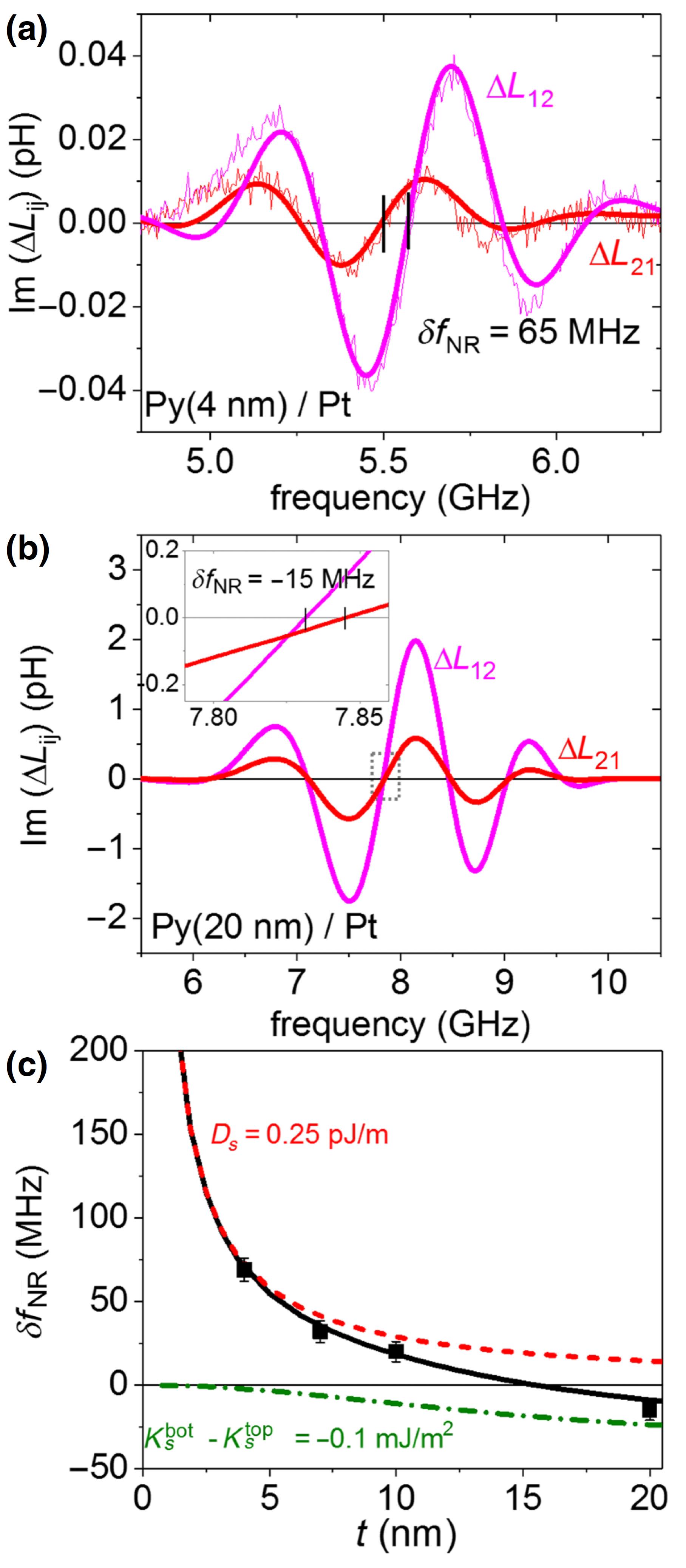
On the brink of this review is the recent paper [285] which investigates interfacial DMI at an oxide-oxide interface, here YIG/GGG. This so called Rashba (or iSGE) induced DMI was recently observed in Avci et al. [7], Ding et al. [80]. Here YIG films with thicknesses 7,10, 20, 40, 80 nm on a GGG substrate were measured by PSWS and from the asymmetric group velocities the DMI constant was calculated. The values were comparable with the ones obtained from BLS.
A very recent work [165] employs a technique which, as in PSWS, exploits the SW non-reciprocity in presence of DMI. The magneto acoustic spin wave (MASW) measurement is experimentally similar to PSWS using a VNA for the detection of the MASW absorption, although it is based on a slightly different physical principle. Via antennas connected to the VNA, surface acoustic waves (SAW) are excited in LiNbO3/CoFeB(1.4-2 nm)/Pt(3 nm) heterostructures which couple to the SWs and generate MASWs with frequencies depending on DMI (see Fig.25). As in a PSWS experiment the value is obtained from the frequency shift between SWs travelling in opposite directions. The non-reciprocity in the resonant field is caused by the DMI as well as the reduced coupling efficiency due to the SAW-SW helicity mismatch for opposite propagation directions.
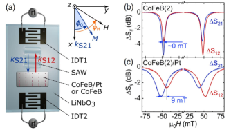
In summary, the electric SW measurement is rather straightforward and only commercially available equipment is required. Among the SW techniques it has a very good frequency resolution of a few MHz. As in the TR-MOKE experiments, the excitation of SWs is performed by CPWs, which have to be prepared by EBL in order to obtain high wave numbers, and therefore larger DMI signals. Usually only few wave vectors are available, since each wave vector requires its own CPW geometry and values are limited to about 10 m-1 using conventional techniques. Only sophisticated techniques allow to reach higher values [183]. A second CPW is used for detecting the spin wave signal and the signal to noise ratio is in generally low, so that only thick FM films (20 nm) give a clear, well measurable signal. However, the resonance frequency can be extracted well also from a noisy signal. More problematic is the analysis of an amplitude non-reciprocity. Since the FM films are rather thick, using gives much larger values than other techniques. This may be due to the fact that is not well estimated since large differences of surface properties might occur. In order to avoid the concept, some groups (Lee et al. [171]), similar to Kostylev [160], attribute the measured DMI value only to a thin layer (monolayer or layer of a characteristic length) close to the interface. This delivers values for an effective value comparable to other techniques, but depends on the arbitrary choice of the characteristic length. However, while it is shown in several works that the dependence does not hold for thicker samples (see e.g. Nembach et al. [222]), the PSWS method particularly confirms this, first because ultrathin films are difficult to be measured, second because the surface character of the Damon Eshbach waves might play a role.
III.3.4 Spin-polarized electron energy loss spectroscopy
Following the theoretical work of Udvardi and Szunyogh [278], the spin wave dispersion asymmetry due to DMI was firstly measured by spin-polarized electron energy loss spectroscopy (SPEELS) on a double layer of Fe(110) grown on W(110) single crystal [304]. A monochromatized spin-polarized electron beam is scattered from the sample and energy loss or gain as a function of in-plane momentum transfer is measured. The minority electrons create surface SWs by a virtual spin flip scattering process and loose energy, while majority electrons may annihilate thermally excited SWs and gain energy. One measures a peak in the minority spin channel in the energy loss region and a peak in the majority spin channel in the energy gain region (analog to the Stokes and Anti-Stokes peak in BLS) [305]. At an electron energy of 4.163 eV (resolution 19 meV) a wave vector of 0.5-1 Å-1 is employed by changing the angle of the incident beam. A small SW dispersion asymmetry is expected due to Damon-Eshbach surface modes of about 0.1 meV. The energy difference for is evaluated by inverting the magnetization direction. The modulus of the DMI vector for first neighbors is 0.9 meV and 0.5 meV for second neighbors. With an interatomic distance of 3.16 and a monolayer thickness 1.72 a value of 3.950.6 mJ/m2 is obtained. In a recent work [277] the technique was taken up again to investigate Co/Fe bilayers with symmetry on W(110) and compared with the previous results. The fundamental role of the crystal symmetry is demonstrated resulting in an extraordinary high DMI. With a thickness of 21.72 a value of 6.550.7 mJ/m2 is obtained.
The main advantage of SPEELS is that the wave vector 500-1200 m-1 is hundreds of times larger than for the above techniques, allowing to explore exchange-based spin waves. Since the energy difference of spin waves with opposite vector grows linearly with the asymmetry detected is about 100 times larger, so that even very small constants can be measured. On the other hand, one can recall the necessity of ultra-high-vacuum conditions and the impossibility of applying magnetic fields. Furthermore, spin wave energies calculated usually from a Heisenberg model have to take into account the itinerant character of the spins in ferromagnetic metals by effective exchange constants. A quantitative estimation of the effective exchange constants (isotropic as well as anisotropic ) requires complex ab initio approaches combined with spin dynamic simulations [27]. This is especially valid for mono- or bilayers of ferromagnets on a heavy metal, as were investigated by SPEELS, where changes in the inter- and intra-layer distances have a non-trivial influence on the exchange parameters [305].
| FM | Bottom NM | Top NM | Sign | Ref | ||
| (nm) | (nm) | (nm) | (mJ/m2) | (pJ/m) | ||
| Fe(2ML)111ML: atomic monolayer | W(110) single crystal | 3.950.6222the value in SI units was taken from the supplemental material of Tsurkan and Zakeri [277], while the original work reports in meV | 1.360.2333the value was obtained assuming a ML thickness of 1.72 | + | 304 | |
| Co(0.4)/Py(5) | Ta(2)/Pt(2) | MgO(5) | 0.16 | 0.89 | - | 159 |
| Co(14-20) | Ta(3)/Pt(3) | MgO(1.8)/Ta(3) | 0.19-0.26 | 3.62-4.08 | -∗ | 171 |
| Ta(3)/MgO(1.8) | MgO(1.8)/Ta(3) | 0.03 | 0.54 | -∗ | ||
| Ta(3)/MgO(1.8) | Pt(3)/Ta(3) | 0.11-0.17 | 2.1-2.55 | +∗ | ||
| Py(6) | Al2O3(21) | Al2O3(5) | 0.007 | 0.04 | - | 102 |
| Co(20) | Ta(2)/Pt(3) | MgO(2) | 0.45 | 9 | -∗ | 135 |
| Co(4-26) | Ta(4)/Pt(4) | Ir(3)/Pt(2) | n.a. | 1.00.2 | - | 188 |
| Ta(4)/Pt(4) | Pt(3)/Pt(2) | n.a. | 0.10.04 | - | ||
| Ta(4)/Ir(4) | Pt(3)/Pt(2) | n.a. | 1.00.2 | + | ||
| Py(4-20) | Ti(5) | Pt(5,10) | n.a. | 0.25 | + | 101 |
| YIG(10) | GGG substrate | 0.00990.0019 | 0.1 | n.a. | 285 | |
| Fe/Co (ML)11footnotemark: 1 | W(110) single crystal | 6.550.7 | 2.250.2533footnotemark: 3 | + | 277 | |
| Co40Fe40B20(2) | LiNbO3 | Pt(3) | 0.4240.001 | 0.850.002 | +∗ | 165 |
III.4 Advantages and Limitations
The main advantage of spin waves methods for determination of the DMI constant is the rather simple expression for the measurable frequency difference that occurs when the sign of is changed, as seen in Eq. 26. This also means that not only the size, but also the sign of the constant can be easily determined, provided that the geometry of the experiment and the polarity of the applied field are specified. However, attention has to be paid to several aspects.
First of all, as it is the case for DW methods, the saturation magnetization should be determined by external means, such as vibrating sample magnetometry (VSM) or SQUID magnetometry. Then, the gyromagnetic factor and the anisotropy constants can be obtained by either FMR or BLS measurements as a function of the intensity and the direction of the external field. Furthermore, the thickness of the magnetic active layer has to be evaluated correctly in the derivation of from measurement of . Not always it coincides with the nominal layer thickness due to interlayer mixing (dead layer) [17] or proximity effects [239]. Finally, it is considered that in Eq. 26 is independent of the sign of . This is in general the case, but when comparing different samples (e.g. with different thicknesses), this might be not perfectly true, for example due to different surface/interface anisotropies at both sides of the magnetic film which influence differently the spin waves and . Therefore, such a difference is necessarily reflected in the measured frequency asymmetry. This problem comes from the fact that DE waves travel on opposite surfaces at opposite directions [41] and therefore any difference in magnetic properties at the two surfaces, as e.g. surface anisotropy, will reflect in a non-reciprocity of the spin wave spectra. By comparison with theoretical models and the correct measurement procedure their contribution has to estimated as far as possible. For example, the asymmetry due to differences in surface anisotropy or asymmetry in saturation magnetisation is evaluated in Di et al. [74] by measuring additionally to a Pt/Co/Ni sample a Co/Ni and a Co/MgO/Ni sample. While in the latter is negligible, meaning that the contribution due to asymmetry in is negligible, the former shows an opposite sign of with respect to the Pt/Co/Ni sample. This means that the two interfaces have different contributions either from anisotropy or DMI, but that a major role is played by the Pt/Co interface with opposite sign with respect to the Co/Ni interface.
Surface effects usually scale as [265, 118] which might open a question on how to distinguish DMI related non-reciprocity from other surface or interface effects. However, the frequency shift due to DMI and surface anisotropy are intrinsically different. As shown in [101] they have different dependencies on as the first is proportional to while the latter to . Furthermore, the first depends linearly on , while the latter has a more complex dependence, but usually decreases with . The wave vector dependence of the frequency shift due to the surface anisotropy is stronger for thicker films, while the one induced by DMI is larger for thinner films (see e.g. supplementary material of [188]). This opens the possibility to distinguish the different contributions, depending on the value of , having available films of different thickness.
It was shown by numeric calculations and experimentally by Stashkevich et al. [266] that for thin films ( 8 nm) the SW reciprocity due to the surface anisotropy is negligible with respect to that induced by DMI, while for thicker films both contributions have to be considered. On the basis of the above arguments, in the literature it is usually considered that at any dependence of on the sign of can be neglected [222] and that, in absence of DMI, the spin waves are subjected to an average magnetic energy equal at both sides of the magnetic film [260].
Care has to be taken not only with respect to frequency non-reciprocity, but also to amplitude non-reciprocity. Also here there might be effects due to different boundary conditions at the interfaces of the ferromagnetic film. For example a metallic boundary condition at one side would attenuate strongly the spin wave travelling close to it. Furthermore, methods as PSWS show an amplitude non-reciprocity due to the fact that the CPW couples more to one wave vector than to the other due to the symmetry of the CPW [252].
Probably the strongest experimental limitation of the methods based on spin waves is that the sample has to be magnetized in-plane in order to be able to detect DE modes. Therefore for samples with strong out-of-plane anisotropy (perpendicular magnetic anisotropy, PMA) it is necessary to apply a sufficiently high in-plane field, which can be experimentally difficult. Furthermore, ultrathin PMA films, give rise to a low signal to noise ratio, not only due to their thickness but often also due to the high damping, so that fitting procedures may have quite large uncertainties. This sets a lower limit to the values of that may be measured by spin wave methods and therefore these may be considered as reliable for either magnetic film thicknesses above a certain threshold, or with low damping, or high DMI constant.
IV Spin Orbit Torque method
IV.1 Method overview
When a charge current is applied to a HM/FM bilayer, spin torque effects occur due to the strong spin-orbit interaction at the interface. A charge current Je flowing in the HM along the axis will generate a transverse spin accumulation along the direction through the spin Hall effect and/or inverse spin Galvanic effect [195]. The spin accumulation acts on the magnetic moment and results in an effective damping-like magnetic field . Of particular interest is the out-of-plane effective magnetic field induced at the Néel-type DW [224]. As shown in Fig. 26, depends on the angle between the DW moment and the axis, and can be quantitatively written as (which represents effectivly Eq. 3), where the charge-to-spin conversion efficiency (effective damping-like field per unit current density) . Here, , , are the effective damping-like torque efficiency, the saturation magnetization of the FM and thickness of the FM layer.
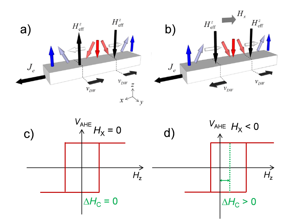
IV.2 Theory and models
Pai et al. [224] first proposed a method to simultaneously determine the spin-torque efficiency and DMI field in HM/FM with PMA, based on current assisted DW propagation model. As shown in Fig. 26(a), in the case of a homochiral Néel-type DW, the net which acts on the DW magnetization is expected to be zero due to the opposite signs of for up-to-down () and down-to-up () DWs. In this case, the opposite at the DWs moves the domain in the same direction and there is no domain expansion. However, when an in-plane external magnetic field is applied that is large enough to overcome , the magnetization in the walls will align parallel to as shown in Fig. 26(b) and the resulting will point along the same direction for both up-to-down and down-to-up DWs. This leads to the expansion or contraction of domains. The magnitude and the polarity of depends on and ., i.e., . Since acts as an effective magnetic field for the device, it is thus expected that the out-of-plane hysteresis loop of the bi-layer can be shifted by . Therefore, by measuring the shift of the hysteresis loop as a function of and , one can determine the magnitude of as well as . Specifically, is determined when the DW is fully aligned by , i.e. , and .
As shown in Fig. 27(a), an anomalous Hall effect (AHE) loop, i.e., an anomalous Hall voltage versus out-of-plane magnetic field, is measured by changing both the magnitude and polarity of and . Under an in-plane bias-field of 0.25 T the AHE-loop shifts to opposite directions at 6 mA, which indicates the opposite sign of the induced due to the SOT. The dependence of the up-to-down switching field and down-to-up switching field is summarized in Fig. 27(c). Two current-related effects should be considered to explain the switching fields, i.e., the effect of Joule heating and . Joule heating reduces the coercivity which is proportional to , i.e., ; while is expected to show a linear behaviour with respect to , i.e., . Thus, for a fixed , the switching field can be written as for up-to-down switching, and for down-to-up switching. By eliminating the effect of Joule heating, the magnitude of can be easily obtained as . As shown in Fig. 27(c), scales linearly with , indicating that is indeed induced by current-induced spin accumulation due to interfacial spin-orbit interaction. One can quantify the conversion efficiency by the slope , and Fig. 27(d) shows the magnitude and polarization of as a function of in-plane bias magnetic-field along x and y directions. One can see that remains zero with the application of , but increases linearly with and saturates at 0.5 T. This observation is in agreement with the domain expansion picture, where the DW magnetization changes from an average value of at to when fully aligns the DW moment, which provides a measure of with . Moreover, the magnitude of is obtained when saturates, from which one can determine the charge-to-spin conversion efficiency .
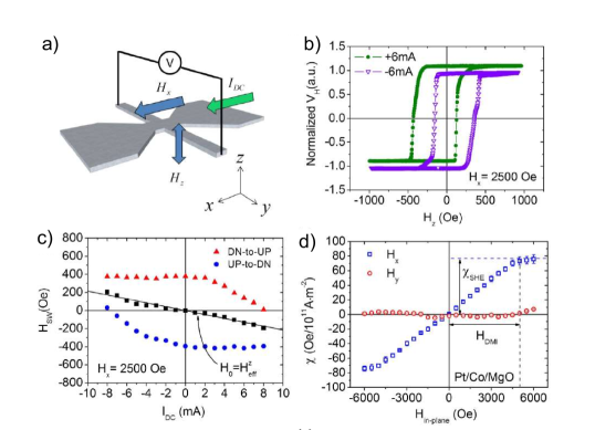
IV.3 Experimental Results
Data of DMI constants determined using the SOT method are reported in Tab. 19. Initially, Pai et al. [224] quantified the magnitude of in Pt/Co/MgO, Pt/CoFeB/MgO and Ta/CoFeB/MgO multilayers, and demonstrated opposite signs of the spin Hall angle for Pt and Ta. They also show that a sizeable DMI exists in wedged Pt/Co(wedge)/MgO samples, where an additional spin-orbit torque appears due to the lateral structure asymmetry and which can be used for in-plane bias magnetic field free switching. By inserting a Pt spacer between a Ta and CoFeB interface, Chen et al. [59] found that both the spin-torque efficiency and the DMI constant gradually decrease as the Pt thickness increases to 1 nm. Note that we did not include ultra thin layers in our summary since the layer formation may not be complete in this case. To generate larger interfacial DMI to support a skyrmion phase, a non centrosymmetric superlattice structure [HM1/FM/HM2]N with PMA is sometimes adopted because of the enhanced interlayer coupling Moreau-Luchaire et al. [216]. Ishikuro et al. [123] demonstrated that the DMI at Ir/Co and Pt/Co interfaces shows comparable magnitude with the same sign, leading to a reduced DMI in Pt/Co/Ir trilayers in agreement with several measurements using BLS and DW methods. Khadka et al. [137] showed that the DMI in Pt/Co/Ru trilayers is comparable to Pt/Co/Ir. Yang et al. [293] measured the spin-orbit torque and DMI in [Ni-Co]/Ir heterostructures. By alloying Cr into Pt, Quan et al. [233] recently found that both the spin-torque efficiency and the DMI can be modulated, reaching a maximum at a Cr concentration of about 25%.
Pai et al. [224] found that in a Pt(4 nm)/Co(1 nm)/MgO(2 nm) stack and a Pt(4 nm)/CoFeB(1 nm)/MgO(2 nm) stack differ by a factor of two. Since DMI is an interfacial effect, the magnitude of is expected to be inversely proportional to the thickness of FM. However, no clear experimental results with the SOT method show this trend indicating that DMI can have a complicated relation to the FM thickness. Interestingly, it has been shown in W/FM/MgO structures (FM = CoFeB, FeB) that changes sign upon increasing the thickness of FM [81], indicating that there could be competing mechanisms contributing to DMI as well as to the interfacial spin-orbit interaction [303, 58, 45].
Recently, measurements have demonstrated the presence of DMI in heavy metal/magnetic insulator heterostrucures, where the DMI is strong enough to stabilize skyrmions [80, 255] and for fast domain motion [7]. Ferrimagnetic insulators are attractive due to their lower Gilbert damping in comparison with ultrathin ferromagnetic metals. Using SOT, Ding et al. [80] quantified the DMI in thulium iron garnet (TmIG)/Pt bi-layers, and have shown that the magnitude of the DMI constant is about 1-2 orders smaller than in metallic heterostructures. They also showed that the magnitude of the DMI constant is inversely proportional to the TmIG thickness, indicating that the DMI in TmIG/Pt bilayer is indeed an interfacial effect. In Ding et al. [78] the origin of the DMI in TmIG/HM bilayers on Gd Garnet (GGG) substrates could be attributed to the GGG/TmIG interface by investigating the FM and HM thickness dependent DMI and SOT.
| FM | Bottom NM | Top NM | HDMI | Ref | ||
| (nm) | (nm) | (nm) | (mT) | (mJ/m2) | (pJ/m) | |
| Co(1) | Pt(4) | MgO(2) | 500 | 3.0 | 3.0 | 224 |
| CoFeB(1) | Pt(4) | 250 | 1.8 | 1.8 | ||
| CoFeB(1) | Ta(6) | 25 | 0.6 | 0.6 | ||
| Co(0.65) | Pt(4) | 110 | 1.45 | 0.94 | ||
| Co(0.80) | Pt(4) | 200 | 1.99 | 1.59 | ||
| Co(0.92) | Pt(4) | 290 | 2.12 | 1.95 | ||
| Co(1.00) | Pt(4) | 400 | 2.64 | 2.64 | ||
| Co(1.10) | Pt(4) | 450 | 2.91 | 3.20 | ||
| Co(1.23) | Pt(4) | 310 | 2.49 | 3.06 | ||
| Co(1.43) | Pt(4) | 160 | 1.62 | 2.32 | ||
| Co(1.52) | Pt(4) | 100 | 1.37 | 2.08 | ||
| Co(0.5) | Pt(4) | Ta(2) | 11010 | 1.010.12 | 0.510.06 | 303 |
| Ta(4) | 11010 | 0.750.09 | 0.380.05 | |||
| Ta(6) | 8010 | 0.700.09 | 0.350.05 | |||
| Ta(8) | 19010 | 1.40.12 | 0.70.06 | |||
| Co(1.2) | Pt(4) | Ir(1) | 656 | 1.090.14 | 1.310.17 | 137 |
| Co(1.2) | Pt(4) | Ir(2) | 818 | 1.420.18 | 1.70.22 | |
| Co(1) | Pt(4) | Ir(1) | 13013 | 2.060.26 | 2.060.26 | |
| Co(1) | Pt(4) | Ru(2) | 140.414 | 2.660.33 | 2.660.33 | |
| Co(0.8) | Pt(4) | Ru(2) | 21221 | 2.400.3 | 1.920.24 | |
| Co(0.8) | Pt(4) | Ru(3) | 21822 | 2.300.29 | 1.840.23 | |
| Co(0.8) | Pt(4) | Ru(4) | 238.624 | 2.560.32 | 2.050.26 | |
| [Pt(1)/Co(0.8)/Ru(1.3)]x2 | Pt(3) | 22022 | 2.070.26 | 1.660.21 | ||
| CoFeB(1.3) | Ta(3) | MgO(1) | 30 | 0.22 | 0.29 | 58 |
| CoFeB(1.4) | Mo(4) | MgO(2) | 20 | 0.35 | 0.49 | 59 |
| FeB(0.96) | -W(4) | MgO(1.6) | 25 | n.a. | n.a. | 81 |
| FeB(0.86) | 30 | n.a. | n.a. | |||
| FeB(0.76) | 18 | n.a. | n.a. | |||
| FeB(0.56) | 50 | n.a. | n.a. | |||
| [Pt(0.6)/Co(0.9)/Ir(0.6)]x3 | Pt(2) | MgO(2) | 80 | 0.4 | 0.36 | 123 |
| [Pt(0.6)/Co(0.9)/Cu(0.6)]x3 | Pt(2) | MgO(2) | 180 | 1.8 | 1.62 | |
| [Pt(0.6)/Co(0.9)/Ir(0.6)]x1 | Pt(2) | MgO(2) | 110 | 0.7 | 0.63 | |
| Co(0.9) | Ir(7) | MgO(2) | 220 | 1.6 | 1.44 | |
| Co(0.9) | Pt(2)/Ir(1) | Ru(1) | 150 | 1.1 | 0.99 | |
| TmIG111Thulium Iron garnet(2.9) | Pt(7) | n.a. | 201 | 0.0360.02 | 0.10.06 | 80 |
| TmIG11footnotemark: 1(2.9-16) | GGG222Gd3Ga5O12 substrate | Pt(7) | 22 - 1.5 | 0.035 - 0.003 | 0.13333the value was obtained from a linear fit over all TmIG thicknesses | 79 |
| TmIG11footnotemark: 1(5.4) | Pt(0.5-7) | n.a. | 0.024 - 0.029 | 0.13444the value was obtained from averaging over all Pt thicknesses | ||
| W(5)/Cu(3) | n.a. | 0.025 | 0.135 | |||
| Cu(3)/Pt(1.5) | n.a. | 0.025 | 0.135 | |||
| Co(0.8) | Cr0.25Pt0.75(8)/Pt(0.4) | AlOx(2) | 100 | 0.87 | 0.70 | 233 |
| [Ni(0.34)/Co(0.16)]2 | Cu(2.5) | Ir(4) | 17.4 | 0.82 | 0.82 | 293 |
IV.4 Advantages and Limitations
Being different from the methods based on DW motion and asymmetric spin-wave propagation, the method based on current-induced shifts of the anomalous Hall loops is a straightforward way for determining the DMI field without involving complicated mathematical models. However, this method requires perpendicular magnetic anisotropy of the ferromagnetic material, which typically limits this method to ultrathin ferromagnetic materials. Non-square shapes of the AHE-loops also lead to inaccuracies in the determination of . To determine the DMI constant, one requires a numerical value for the exchange stiffness; usually an assumed value is used. Moreover, this method is not capable to determine the sign of DMI.
V Comparison of the methods and discussion of problems in the determination of the DMI constant
V.1 Comparing the DMI constants obtained by the different methods
When comparing the DMI constant measured by different methods, it becomes clear that the values sometimes do not coincide within the uncertainties of different measurements, or are even vastly different (as shown in Figs. 28-29), even if the measured stacks are nominally the same or at least very similar. As examples shown in Fig. 28, disagreement on the values are found for Pt/Co/Ir stacks (measured by nucleation, DW creep and BLS), Pt/Co/Ta stacks (measured by BLS, domain pattern and SOT) or Pt/Co/AlOx and Pt/Co/MgO (measured by stripe annihilation, BLS and DW flow). Therefore, it is important not only to consider the advantages and limitations of each individual method, which influences their applicability, but also their intrinsic differences, which might influence the measurement result. The aim of this section is to discuss the intrinsic differences and make some hypotheses about their influence on the measurement result, although currently systematic studies comparing the various methods are unfortunately rare. Furthermore, in most of the available studies, samples are investigated where the different techniques agree well, while the disagreement is rarely discussed. We suppose that the presence of defects or disorder evidences some of the intrinsic differences between the techniques. In general, methods based on domain wall motion are affected by the fact that pinning influences DW dynamics. Pinning is a local phenomenon that - in the case of domain wall motion - may nevertheless have a global influence on the average domain wall movement and thus may complicate the quantitative determination of . Furthermore, quasistatic methods based on imaging usually rely on observing the DW or a number of domains in a certain position, and therefore close to pinning sites. They depend on the local energy landscape at a pinning site which may be different from the one far from the pinning site and the result of the measurement may vary even from spot to spot in a single sample due to the distribution of inhomogeneities and defects. Analytical models and simulations usually do not take these imperfections into account and use average parameters, which may lead to intrinsic errors. Considering a larger sample area may reduce such an effect. Also nucleation of domains, as it is needed also for measurements in creep regime, occurs at pinning sites and single measurements may not be representative. In addition, strain in the thin films might play a role and, in fact, several recent works investigate defect- or strain-induced DMI [89, 208, 72]. Therefore, a statistic assessment across a wafer, measuring at many different locations, could help to understand more about defect related differences in the measurements, but is currently lacking in the literature.
Dynamic methods often average out these effects. Note however, that an average value obtained across a large film area in presence of inhomogeneities might not represent the intrinsic value. DW creep motion can be considered an intermediate regime, where DWs move due to thermal activation from one pinning site to the next. These measurements show generally good agreement with static methods, such as the stray field measurements by NV center magnetometry [261, 104]. However, measurements in the creep regime require simplified models of the domain wall dynamics, as detailed in section II.2. In fact, concerning measurements of DW motion in the creep regime by asymmetric bubble expansion, there are currently various models proposed which evaluate the DMI from the domain velocity profile and fit the data to extract the DMI field. In addition, the evaluation of the DMI constant depends on the DW width or the DW energy, parameters known only up to a certain accuracy. They are often calculated from the exchange stiffness and the anisotropy constant. Both parameters should be therefore determined experimentally, which requires a substantial effort especially for the exchange stiffness in thin films. At that point direct measurements of the DW width by imaging techniques may become a valuable alternative, even if pretty much more complicated.
SW methods have the advantage of a more straightforward evaluation of the DMI constant by measuring a frequency shift, which is possible with high accuracy. Concerning the model, only the gyromagnetic ratio and the saturation magnetization have to be known (the exchange constant is not needed for long wavelength SWs), parameters more easily to be accessed experimentally. Pinning sites usually do not influence the dispersion relation of spin waves directly, but only affect the measured spin wave decay length which is reflected in the line width in frequency domain methods. The most widely employed, direct and effective method is BLS, as it does not require any external spin wave transduction or any kind of patterning, contrary to TR-MOKE and PSWS. Influence of defects, grain boundaries, inclusions and surface roughness play a marginal role, as is generally the case for the spin wave methods. To this respect, it has also to be considered that the revealed SW have wavelength ranging from half a m to a few microns and that measurements average over a rather large sample area. In the case of BLS and TR-MOKE the typical spot size is of the order of 10 m and in the case of PSWS a typical CPW is also about 10 m long, while DWs have a width of the order of 10 nm. Moreover, the propagation distance of SW, even for thermal SW detected by BLS, is of the order of several microns and the influence of nanometric inhomogeneities is averaged out (for instance they may result in a broadening of the BLS peaks, with a minor influence on the mean frequency) so that SW methods are rather insensitive to them due to the different length scales involved. Another simplification of spin wave methods might be that the measurement does in general not require measuring (and evaluating by a model) the spin wave dispersion itself but only the difference , and is therefore a kind of differential method.
The differences in applicability of the various methods explain why a direct comparison on the same sample is rarely reported in the literature. Only in few papers [280, 261, 143, 254, 229, 167], a quantitative comparison of the values of is reported, measured by both BLS and DW-based methods. In general, a reasonable agreement is attained for the different systems if BLS results are compared to those extracted from analysis of DW motion in the flow-regime191919Note, however, that the DW methods use additional parameters with respect to the spin wave methods, as e.g. the exchange stiffness, which may be adapted in order to fit the BLS results.. Instead, when DW motion is analysed in the creep regime, the values obtained by DW-based methods are generally significantly higher or lower than those obtained by BLS. As mentioned, this may depend critically on the accurate analysis of the measured creep data. However, while in the creep regime disorder plays a crucial role, spin wave propagation might be rather insensitive to it. This could be owing to the different magnetic state necessary for the measurement: in the creep regime (nucleating and expanding a bubble domain) the measurement is performed at small applied fields, so at a state where the energy landscape starts to vary locally. Instead the spin wave methods are applied close to saturation, where disorder in the magnetization state becomes negligible. The level of discrepancy may be also strongly influenced by the material properties and layer combinations, as well as by the specific thickness and chosen substrate [261, 254]. In fact, since in the thin film systems DMI is an interface effect, details concerning the structural and chemical quality of the materials, in particular of the interfaces, play a crucial role and should be stated in the papers. Furthermore, in order to judge the relative accuracy and reliability of different methods it is indispensable to compare measurements performed on identical samples and a more intense research effort should respond to this need.
Concerning methods that determine the DMI field under the influence of a current (such as current induced DW motion and SOT field measurements), the main difficulty is the interpretation of the results, taking into account the different contributions of spin orbit torques. Damping and field like torques may have different origins as the SHE and the iSGE, and both contribute to the observed dynamics. Furthermore, in metallic stacks, the current flow in the plane is not well defined as it is partly in the FM and partly in the HM material, depending on the relative resistances and the interface scattering and transparency [267].
An attempt to classify the applicability of three methods (BLS, SOT efficiency, and DW velocity) according to DMI strength and FM layer thickness was performed by Kim et al. [143]. According to their scheme, BLS applies better to larger values and FM film thicknesses, while DW methods are suitable for smaller values, instead SOT applies to small values of , but higher FM layer thicknesses. In an intermediate range all three methods are applicable and a direct comparison of the methods on the same sample is possible. In fact for the samples Pt(2.5)/Co(0.9)/X(2.5) (X = Ti, Ta, Al, Pt) they find an excellent agreement within a 5% difference. While in the case of Pt/Co/W, a 10% difference between DW-based and SW-based methods occurs, and Pt/Co/Cu presents a much larger 40% difference. They argue that the limitation of BLS for measuring low DMI values is the interferometer resolution, while in film thickness, supposing films with PMA, it is due to to the high fields necessary to overcome the out-of-plane anistropy. DW velocity and SOT methods are limited in measuring high DMI values by the maximum in-plane field that can be applied. The DW velocity is limited to smaller film thicknesses by chiral damping [145] with respect to the SOT method where spin transfer torque contributes, instead at higher thicknesses both are limited due to dendrite domain formation. The above considerations are corroborated by a synoptic view of the Tables of results and Figs. 28, and 29 discussed later: one may find that in several examples of nominally similar systems, different groups obtained relatively different results. In this context, even if BLS seems at the moment the most popular and efficient method to determine DMI in layered systems, more systematic multi-technique investigation of the DMI on the same samples, for different materials combination and layer thicknesses (including a cross-check concerning the mutual consistency of results relative to different regions on the same sample) would be highly desirable.
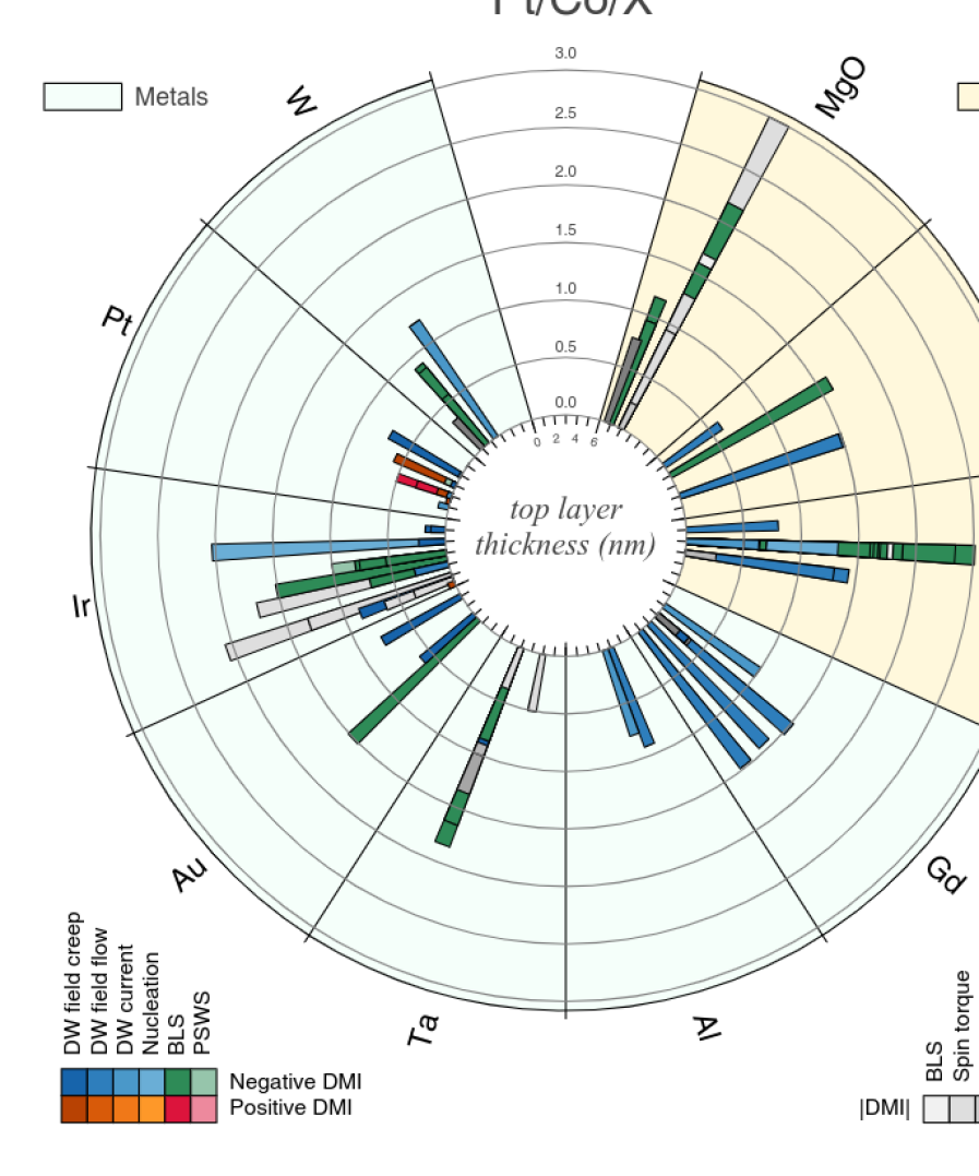
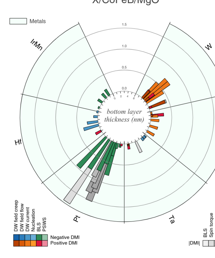
V.2 Comparing the DMI constants in different materials
The two most common material combinations investigated in the literature are heterostructures of a) HM/CoFeB/MgO and b) Co with Pt as a top or bottom layer. We begin by focusing on Pt/Co/X heterostructures, with the top layer X = W, Pt, Ir, Au, Ta, Al, Gd, AlOx, GdO, and MgO, as shown in Fig. 28. When the sign of is not available a gray scale is used, otherwise a positive sign is indicated by orange/red palette and negative by a blue/green one. The sign is mostly negative because it is dominated by the Pt/Co interface which gives a negative sign (according to the conventions used in this paper). The oxides, AlOx, GdO and MgO, as top layers show the largest (negative) DMI values [37], with the record (excluding PSWS measurements) of 3 pJ/m in Pt(4)/Co(1)/MgO(2) thin films measured using the spin-orbit torque method [224]. One could therefore assume that all the top layers contribute with a negative , adding up to the total negative measured. In Chaves et al. [51] it was shown by investigating oxide wedge samples that the Co/Ox interface (with = Al or Gd) gives a contribution to the DMI caused by the Pt underlayer which depends on the oxidation state and that by tuning the Co oxidation an optimization of DMI can be reached. However, a positive sign for (not shown in the figure) was reported measured by PSWS in Pt/Co/MgO films with a thick Co layer (up to 20 nm) [171, 135]. The other elements as top layers show more or less contradicting results, as for Ta, Pt, and Ir. The stacks Pt/Co/Ir/X stacks show a large variety in magnitude and sign, for instance. Note that the introduction of an Ir thin layer in Pt/Co/Ir/Pt reduces the magnitude of and changes the sign for thicker Ir [121]. In Ir/Co/MgO a negative value for was found by BLS, concluding that Ir contributes as a bottom layer with a negative DMI and positive as a top layer, so in the same way as Pt. This fact is in contrast with the theoretical prediction that the contribution of the interface Ir/Co was opposite to that of Pt/Co [296, 292]. Opposite contributions would make it possible to increase the DMI by fabricating Pt/Co/Ir trilayers. As discussed in Sections II.3.2 and IV, the combination Pt/Co/Ir seems to give smaller values than the addition of the values. Furthermore, Ir as a bottom layer gives a positive measured by BLS in Ir/CoFeB/MgO and a negative value for Ir/Co/MgO, so the sign does also depend on the ferromagnetic material. A simple addition of values of top and bottom interfaces seems not to be feasible, as is also shown for Pt/Co/W. Even though W contributes with opposite sign to the DMI with respect to Pt and its contribution to the DMI strength in general is higher than for FM/oxide interfaces, the total DMI value of the stack is smaller than the one obtained by Pt/Co/oxide stacks. The addition of values of the top and bottom interface can be discussed at the Pt/Co/Pt stack. For instance, films with the same thickness of the two Pt layers should, in principle, have a zero DMI, as for epitaxial films. However, a perfect or nearly-perfect compensation of the top/bottom contributions is found in a few cases [229, 144, 1, 143, 19, 100] (not shown in figure), and more generally small values of DMI are found, both positive and negative, as shown in figure. Additionally, current-induced motion experiments in Pt/Co/Pt samples show negative values independent of the thickness of top or bottom layer [95], while creep regime experiments give mostly positive values. In summary, Fig.28 points out the strong influence of film preparation, differences in interface properties of top and bottom layers, etc. on the DMI, which explain the high variability in magnitude and sign of the .
The interpretation of the data for the X/CoFeB/MgO heterostructures (with X = IrMn, Hf, Pt, Ta, TaN, W as shown in Fig. 29), is a bit more clear202020Note: The plot contains both compositions of CoFeB, the Fe rich Co20Fe60B20 and the Co rich Co40Fe40B20.. Similarly to the previous figure, methods not able to determine the sign are shown with gray palette, while positive signs are indicated by a orange/red palette and negative signs by the blue/green one. In general, the different methods give values compatible in magnitude, with the exception of Pt/CoFeB/MgO, where BLS and domain pattern/spin torque methods diverge. The CoFeB/MgO bilayer sputtered directly on the substrate (so without bottom layer X) has a small positive pJ/m [59]. This value is compensated in the case of Pt and IrMn bottom layers showing a negative for the largest thickness (up the maximum value of about -1.75 pJ/m for the Pt layer, measured by spin torque methods). On the contrary, W and TaN increase the positive value of , up to about 0.7 pJ/m for the W layer. Less clear is the contribution of Hf and Ta. Hf leads to a negative obtained by current-induced domain wall motion measurements for a film thickness larger than 2 nm, while a positive is obtained in the creep regime and by BLS for a 1 nm thick layer. It is interesting to note that the negative value is decreasing as the Hf becomes thicker, while for Pt or IrMn increases for thicker films. Ta gives a variation of from negative to positive when increasing the thickness, measured by current-induced domain wall motion [276], which is in contradiction with the positive value for the stack without bottom layer. Furthermore, Karnad et al. [134] reported different signs when measuring by creep regime and by current-induced domain wall motion. This contradiction may originate from the small value of in those Ta samples.
Despite all these difficulties, a few conclusions can be reached concerning the sign and strength of the DMI. If the order of the stack is reversed, then one finds a reversal of the sign by symmetry. The strength of the DMI may be different due to the different growth conditions of a reversed stack, but the sign reversal is effectively verified as in Pt/Co/Ta and Ta/Co/Pt trilayers measured by BLS [60]. All the BLS experiments are consistent with a negative (positive) value of for a Pt bottom (top) layer regardless the FM composition, as verified for CoFeB, Co, Co/Ni, Ni80Fe20, and independent of whether the top layer is an oxide or another heavy metal. This result is also consistent with the sign detected for current-induced domain wall motion and field driven motion in the flow regime. Concerning the absolute value of , the highest values are obtained for Pt/FM interfaces in combination with oxide top layers. In general, Co seems to be more sensitive to the interface quality and more contradictions are found in the literature. Clear trends are observed for CoFeB compounds concerning a) the sign, as Pt as a bottom layer gives negative sign, while Ta and W give positive ones; and b) the trend in HM thickness dependence, increasing with a saturation value for Pt, decreasing for Hf and non monotonic for W with a maximum value for an intermediate thickness.
V.3 Influence of growth conditions on the DMI constant
Due to the large spread of materials used, the investigation of the influence of growth condition on DMI is not conclusive so far. Wells et al. [287] studied the effect of sputter-deposition conditions on DMI in Pt/Co/Pt structures. They found that the growth temperature modifies the interfacial roughness. The different quality of the top Pt/Co interface and the lower Co/Pt one introduces a structural inversion asymmetry, which results in a net DMI field in this nominally symmetric structure. This explains the discrepancies of the sign of for Pt/Co/Pt stacks as mentioned in II.3.2. Regarding the effect of post annealing, Khan et al. [138] studied the influence of annealing on DMI in Ta/CoFeB/MgO. Here the DMI field is determined by magnetic field driven domain motion in the creep regime. They found that both and the DMI constant vary with annealing temperature, reaching a peak at 230 ∘C and then decreasing as the temperature is further increased. They also found that the dependence of interfacial perpendicular magnetic anisotropy field on annealing temperature follows a similar trend as DMI, suggesting a connection between these parameters. They suggested that the increase of and is due to an improved ordering of atoms at the Ta/CoFeB interface. Higher annealing temperature leads to diffusion of B atoms out of CoFeB as well as intermixing at the interface, which significantly reduces and . Cao et al. [42] also reported a similar trend in annealing temperature dependence of in Pt/Co/x/MgO structures (x = Mg or Ta) investigated by magnetic field driven domain motion. A maximum is obtained at an annealing temperature of 300 ∘C, which is independent of the MgO thickness. Similar to Khan et al. [138], they also propose that the enhanced is due to the improved crystalline quality upon annealing. However, Furuta et al. [96] used current-driven domain wall motion to study the effect of annealing on in Pt/[Co/Ni] structures. They show that annealing causes a significant reduction of , domain wall velocity, perpendicular magnetic anisotropy, as well as spin-orbit torques, which is attributed to the diffusion of Co atoms across the Pt/Co interface.
V.4 Outlook and conclusion
In this review nearly than one hundred and fifty articles measuring interfacial DMI have been analyzed. The interest in this topic is still growing, as illustrated by the rapidly increasing number of publications and citations. It may be surprising that only in recent years the topic of chiral magnetism gained such a relevance in the research community, as parity breaking and chirality is intrinsic to magnetic systems.
New opportunities have been foreseen recently moving the interest away from the traditional HM/FM bilayers towards synthetic antiferromagnets (SAF) and oxides. SAFs exploit the RKKY exchange interaction between two ultrathin FM layers separated by a non magnetic spacer layer, which can be tuned by the spacer layer thickness [83]. In these systems, with a HM as spacer layer, it was shown that the DMI is enhanced by the dipolar field between the FM layers [89, 204]. Besides having the advantages of antiferromagnets, such as negligible stray fields and stability against magnetic fields [13], these SAFs exhibit asymmetric DWs and spin wave dynamics. The possibility of tailoring DMI in SAFs makes them extremely interesting for applications of chiral magnetism and topological spin structures [173, 281]. Since this topic goes slightly beyond the review, it is not included in the tables, however it is worth mentioning the upcoming interest in SAFs [109, 34, 269, 277, 204, 89].
A second topic that has come up recently, and which brings us to the microscopic origin of DMI, is DMI in FM oxides [285] and oxidized metallic FM [221] which is not fully understood, yet, but might be related to local charge transfer at the interfaces. In [221] the enhanced DMI is suggested to be caused by an electric dipole moment induced by hybridization and charge transfer at the oxygen/FM metal interface [15]. This iSGE-induced DMI [149] was also observed for a Co/graphene interface [295]. In both cases density functional theory (DFT) calculations were fundamental to interpret the results and the calculations showed that the DMI originates from the FM layer, instead of the HM layer [294, 295]. However, the fact that hybridization at the interface plays an essential role makes the analysis complex and categorizing materials or stacks according to their DMI strength becomes almost impossible. Interface intermixing, interface roughness, dead layers and proximity effects all were known to affect the DMI. In fact, a detailed interface characterization should be performed in order to obtain a complete picture. Although clearly certain materials give higher DMI than others, the interfacial DMI may depend on the interface properties more than on material properties themselves. For example, annealing may change the DMI value by about 20-30% [23] or exchanging top and bottom layer in Cho et al. [60] leads to changes of about 30%. The iSGE-induced DMI is closely related to materials for spin-to-charge conversion which recently attracted attention [57, 235, 79]. A key feature is again the mechanism of SOC, but not necessarily a material with strong SOC, such as HM, is required, but SOC can also be induced at the interface by the iSGE. Similar to other SOC related phenomena (such as spin-orbit torques), the origin of DMI, either from bulk SOC or SOC at the interface, is impossible to disentangle, and have to be treated in a common theoretical approach. The DMI was firstly described by a phenomenological thermodynamic theory, but it appears now fundamental, for developing materials designed for future applications, that the microscopic origin of DMI has to be understood in more detail.
A third new emerging topic investigates the possibility to stabilize chiral spin textures in centrosymmetric magnetic insulators, where high DW speeds (up to 400 ms-1 are reached with minimal currents of A/cm [282]. In systems like Tm3Fe5O12 (TmIG) a small DMI of the order of a few J/m2 has been detected in DW racetracks, and confirmed by scanning nitrogen-vacancy magnetometry. In particular, TmIG thin films grown on Gd3Sc2Ga3O12 exhibit left-handed Néel chirality, changing to an intermediate Néel-Bloch configuration upon Pt deposition. Similarly, 170 show that Pt, W, and Au induce strong interfacial DMI and topological Hall effect, while Ta and Ti cannot, providing insights into the mechanism of electrical detection of spin textures in these magnetic insulator heterostructures.
A fourth and very important research field is that related to the search for systems with large and tailored DMI, paving the way towards the stabilization and exploitation of topological spin structures, such as spirals, helices, merons, skyrmions and anti-skyrmions at temperatures well above room temperature and supporting high-frequency dynamics [93]. This would represent a clear advantage to move towards applications, where non-equilibrium operation is needed to achieve fast switching and information processing. In this respect, the stabilization of topological magnetic objects and the control of their dynamical properties can be made more efficient and reliable by patterning periodic arrays of two-dimensional dots or anti-dots. These systems are also the battleground of the rising and exciting field of magnonics, where information is carried and manipulated by spin waves propagating in periodically modulated media, i.e. artificial magnonic crystals. Integration of DMI in magnonic crystals is expected to open unexplored possibilities, due to the appearance of a sizeable asymmetry in the magnonic band structure, enabling the possibility of unidirectionally energy transfer and magnetic damping tuning [97]. In this context, the concept of topologically protected chiral edge spin waves existing in the bandgap of a topological magnetic material and propagating in a certain direction with respect to the bulk magnetization direction appears to be very promising [286]. Based on this idea, reconfigurable topological spin-wave diodes, beam splitters, and interferometers can be in principle designed and realized for new devices for information and communication technology.
Finally, even if this review was focused on experimental methods and results, it is clear that new challenges and advances for this research field, also in terms of functionalization/engineering of materials, are connected with achieving a better understanding of the microscopic origin of DMI, relying on quantum mechanical and atomistic calculations [296] and integrating them into a multiscale modelling chain, whose uppermost level are the micromagnetic simulations able to mimic the behavior of real devices. One necessary step for this goal will be to shortcut the gap existing between research communities that use either classical or quantum physics, so as to setup efficient computer codes, operating in a multiscale framework, capable of providing quantitative predictions and recipes for the next generation of materials and devices. In terms of experiments, characterising the atomic scale details of real interfaces is a huge but important challenge that must be met in order to tease out the ultimate causes of the variation in DMI observed among the disparate reports to date.
Acknowledgment
The project 17FUN08-TOPS has received funding from the EMPIR programme co-financed by the Participating States and from the European Union’s Horizon 2020 research and innovation programme. F.G.S. acknowledges the support from Project No. SA299P18 from the Consejería de Educación of Junta de Castilla y León. L.C. and C.B. acknowledge the support from DFG through SFB 1277. C.H.M. acknowledges support from the EPSRC, grant number EP/T006803/1. G.D. acknowledges the support from the European Union H2020 Program (MSCA ITN 860060). We kindly thank G. Chen, A. Schmid and T.P. Ma for the unit conversion of the values in Table 13. M.K. thanks H. T. Nembach, J. M. Shaw and A. Magni for fruitful discussions. A special thank to P. Landeros for critical reading of the manuscript and useful suggestions.
References
- Agrawal et al. [2019] Agrawal, Parnika, Felix Büttner, Ivan Lemesh, Sarah Schlotter, and Geoffrey S. D. Beach (2019), “Measurement of interfacial Dzyaloshinskii-Moriya interaction from static domain imaging,” Phys. Rev. B 100 (10), 104430.
- Ahmadi et al. [2020] Ahmadi, Khadijeh, Loghman Jamilpanah, Seyed Ali Seyed Ebrahimi, Abbas Olyaee, Mohammad Mehdi Tehranchi, and Seyed Majid Mohseni (2020), “Observation of the Dzyaloshinskii–Moriya interaction via asymmetry in magnetization reversal,” J. Phys. D 53 (46), 465001.
- Ajejas et al. [2017] Ajejas, Fernando, Viola Křižáková, Dayane de Souza Chaves, Jan Vogel, Paolo Perna, Ruben Guerrero, Adrian Gudin, Julio Camarero, and Stefania Pizzini (2017), “Tuning domain wall velocity with Dzyaloshinskii-Moriya interaction,” Appl. Phys. Lett. 111 (20), 202402.
- Albornoz et al. [2021] Albornoz, Lucas J, Ezequiel E. Ferrero, Alejandro B. Kolton, Vincent Jeudy, Sebastian Bustingorry, and Javier Curiale (2021), “Universal Critical Exponents of the Magnetic Domain Wall Depinning Transition,” arXiv:2101.06555v2 .
- Arias and Mills [1999] Arias, Rodrigo, and D. L. Mills (1999), “Extrinsic contributions to the ferromagnetic resonance response of ultrathin films,” Phys. Rev. B 60 (10), 7395–7409.
- Arora et al. [2020] Arora, Monika, Justin M. Shaw, and Hans T. Nembach (2020), “Variation of sign and magnitude of the Dzyaloshinskii-Moriya interaction of a ferromagnet with an oxide interface,” Phys. Rev. B 101 (5), 54421.
- Avci et al. [2019] Avci, Can Onur, Ethan Rosenberg, Lucas Caretta, Felix Büttner, Maxwell Mann, Colin Marcus, David Bono, Caroline A. Ross, and Geoffrey S. D. Beach (2019), “Interface-driven chiral magnetism and current-driven domain walls in insulating magnetic garnets,” Nat. Nanotechnol. 14 (6), 561–566.
- Baćani et al. [2019] Baćani, Mirko, Miguel A. Marioni, Johannes Schwenk, and Hans J. Hug (2019), “How to measure the local Dzyaloshinskii-Moriya interaction in skyrmion thin-film multilayers,” Sci. Rep. 9 (1), 3114.
- Bailleul et al. [2003] Bailleul, M, D. Olligs, and C. Fermon (2003), “Propagating spin wave spectroscopy in a permalloy film: A quantitative analysis,” Appl. Phys. Lett. 83, 972.
- Bailleul et al. [2001] Bailleul, M, D Olligs, C Fermon, and S. O Demokritov (2001), “Spin waves propagation and confinement in conducting films at the micrometer scale,” Europhys. Lett. 56 (5), 741–747.
- Bak and Jensen [1980] Bak, P, and M H Jensen (1980), “Theory of helical magnetic structures and phase transitions in MnSi and FeGe,” J. Phys. C: Solid State Phys. 13 (31), L881.
- Balk et al. [2017] Balk, A L, K-W. Kim, D. T. Pierce, M. D. Stiles, J. Unguris, and S. M. Stavis (2017), “Simultaneous control of the Dzyaloshinskii-Moriya interaction and magnetic anisotropy in nanomagnetic trilayers,” Phys. Rev. Lett. 119 (7), 077205.
- Baltz et al. [2018] Baltz, V, A Manchon, M Tsoi, T Moriyama, T Ono, and Y Tserkovnyak (2018), “Antiferromagnetic spintronics,” Rev. Mod. Phys. 90, 015005.
- Bauer et al. [2014] Bauer, H G, J.-Y. Chauleau, G. Woltersdorf, and C. H. Back (2014), “k-vector distribution of magneto-static spin waves excited by micro-fabricated antenna structures,” in Springer Proceedings in Physics (Springer International Publishing) pp. 83–85.
- Belabbes et al. [2016] Belabbes, A, G Bihlmayer, F Bechstedt, S Blügel, and A Manchon (2016), “Hund’s rule-driven Dzyaloshinskii-Moriya interaction at 3d-5d interfaces,” Phys. Rev. Lett. 117, 247202.
- Belmeguenai et al. [2017] Belmeguenai, M, H. Bouloussa, Y. Roussigné, M. S. Gabor, T. Petrisor, C. Tiusan, H. Yang, A. Stashkevich, and S. M. Chérif (2017), “Interface Dzyaloshinskii-Moriya interaction in the interlayer antiferromagnetic-exchange coupled Pt/CoFeB/Ru/CoFeB systems,” Phys. Rev. B 96 (14), 144402.
- Belmeguenai et al. [2018] Belmeguenai, M, M. S. Gabor, Y. Roussigné, T. Petrisor, R. B. Mos, A. Stashkevich, S. M. Chérif, and C. Tiusan (2018), “Interfacial Dzyaloshinskii-Moriya interaction sign in Ir/Co2FeAl systems investigated by Brillouin light scattering,” Phys. Rev. B 97 (5), 054425.
- Belmeguenai et al. [2016] Belmeguenai, M, M. S. Gabor, Y. Roussigné, A. Stashkevich, S. M. Chérif, F. Zighem, and C. Tiusan (2016), “Brillouin light scattering investigation of the thickness dependence of Dzyaloshinskii-Moriya interaction in Co0.5Fe0.5 ultrathin films,” Phys. Rev. B 93 (17), 174407.
- Belmeguenai et al. [2019] Belmeguenai, M, Y. Roussigné, S. M. Chérif, A. Stashkevich, T Petrisor, M Nasui, and M S Gabor (2019), “Influence of the capping layer material on the interfacial Dzyaloshinskii–Moriya interaction in Pt/Co/capping layer structures probed by Brillouin light scattering,” J. Phys. D 52 (12), 125002.
- Belmeguenai et al. [2015] Belmeguenai, Mohamed, Jean-Paul Adam, Yves Roussigné, Sylvain Eimer, Thibaut Devolder, Joo-Von Kim, Salim Mourad Cherif, Andrey Stashkevich, and André Thiaville (2015), “Interfacial Dzyaloshinskii-Moriya interaction in perpendicularly magnetized Pt/Co/AlOx ultrathin films measured by Brillouin light spectroscopy,” Phys. Rev. B 91 (18), 180405(R).
- Benguettat-El Mokhtari et al. [2019] Benguettat-El Mokhtari, I, A. Mourkas, P. Ntetsika, I. Panagiotopoulos, Y. Roussigné, S. M. Cherif, A. Stashkevich, F. Kail, L. Chahed, and M. Belmeguenai (2019), “Interfacial Dzyaloshinskii-Moriya interaction, interface-induced damping and perpendicular magnetic anisotropy in Pt/Co/W based multilayers,” J. Appl. Phys. 126 (13), 133902.
- Benguettat-El Mokhtari et al. [2020a] Benguettat-El Mokhtari, I, D. Ourdani, Y. Roussigné, R.B. Mos, M. Nasui, S.M. Chérif, A. Stashkevich, M.S. Gabor, and M. Belmeguenai (2020a), “Investigation of the correlation between perpendicular magnetic anisotropy, spin mixing conductance and interfacial Dzyaloshinskii–Moriya interaction in CoFeB-based systems,” J. Phys. D 53 (50), 505003.
- Benguettat-El Mokhtari et al. [2020b] Benguettat-El Mokhtari, I, D. Ourdani, Y. Roussigné, R.B. Mos, M. Nasui, F. Kail, L. Chahed, S.M. Chérif, A. Stashkevich, M. Gabor, and M. Belmeguenai (2020b), “Perpendicular magnetic anisotropy and interfacial Dzyaloshinskii–Moriya interaction in as grown and annealed X/Co/Y ultrathin systems,” J. Phys.: Cond. Mat. 32 (49), 495802.
- Benguettat-El Mokhtari et al. [2020c] Benguettat-El Mokhtari, I, Y. Roussigné, S. M. Chérif, A. Stashkevich, S. Auffret, C. Baraduc, M. Gabor, H. Béa, and M. Belmeguenai (2020c), “Interface phenomena in ferromagnet/-based systems: Damping, perpendicular magnetic anisotropy, and Dzyaloshinskii-Moriya interaction,” Phys. Rev. Mat. 4, 124408.
- Benitez et al. [2015] Benitez, M J, A. Hrabec, A. P. Mihai, T. A. Moore, G. Burnell, D. McGrouther, C. H. Marrows, and S. McVitie (2015), “Magnetic microscopy and topological stability of homochiral Néel domain walls in a Pt/Co/AlOx trilayer,” Nat. Commun. 6 (1), 034008.
- Berger [1996] Berger, L (1996), “Emission of spin waves by a magnetic multilayer traversed by a current,” Phys. Rev. B 54, 9353–9358.
- Bergqvist et al. [2013] Bergqvist, Lars, Andrea Taroni, Anders Bergman, Corina Etz, and Olle Eriksson (2013), “Atomistic spin dynamics of low-dimensional magnets,” Phys. Rev. B 87 (14), 1–12.
- Bloch [1932] Bloch, F (1932), “Zur theorie des austauschproblems und der remanenzerscheinung der ferromagnetika,” Z. Physik 74, 295–335.
- Bode et al. [2007] Bode, M, M. Heide, K. von Bergmann, P. Ferriani, S. Heinze, G. Bihlmayer, A. Kubetzka, O. Pietzsch, S. Blügel, and R. Wiesendanger (2007), “Chiral magnetic order at surfaces driven by inversion asymmetry,” Nature 447 (7141), 190–193.
- Bogdanov and Hubert [1994] Bogdanov, A, and A. Hubert (1994), “Thermodynamically stable magnetic vortex states in magnetic crystals,” J. Magn. Magn. Mat. 138 (3), 255–269.
- Bogdanov and Rößler [2001] Bogdanov, A N, and U. K. Rößler (2001), “Chiral symmetry breaking in magnetic thin films and multilayers,” Phys. Rev. Lett. 87 (3), 037203.
- Bogdanov et al. [2002] Bogdanov, A N, U. K. Rößler, M. Wolf, and K.-H. Müller (2002), “Magnetic structures and reorientation transitions in noncentrosymmetric uniaxial antiferromagnets,” Phys. Rev. B 66 (21), 214410.
- Bogdanov and Yablonskii [1989] Bogdanov, A N, and D. A. Yablonskii (1989), “Thermodynamically stable ”vortices” in magnetically ordered crystals. The mixed state of magnets,” Zh. Eksp. Teor. Fiz. 95 (1), 178–182.
- Bollero et al. [2020] Bollero, Alberto, Volker Neu, Vincent Baltz, David Serantes, José Luis F. Cuñado, Javier Pedrosa, Ester M. Palmero, Marietta Seifert, Bernard Dieny, Rafael P. Del Real, Manuel Vázquez, Oksana Chubykalo-Fesenko, and Julio Camarero (2020), “An extraordinary chiral exchange-bias phenomenon: Engineering the sign of the bias field in orthogonal bilayers by a magnetically switchable response mechanism,” Nanoscale 12 (2), 1155–1163.
- Boulle et al. [2012] Boulle, O, L. D. Buda-Prejbeanu, M. Miron, and G. Gaudin (2012), “Current induced domain wall dynamics in the presence of a transverse magnetic field in out-of-plane magnetized materials,” J. Appl. Phys. 112 (5), 053901.
- Boulle et al. [2013] Boulle, O, S. Rohart, L. D. Buda-Prejbeanu, E. Jué, I. M. Miron, S. Pizzini, J. Vogel, G. Gaudin, and A. Thiaville (2013), “Domain wall tilting in the presence of the Dzyaloshinskii-Moriya interaction in out-of-plane magnetized magnetic nanotracks,” Phys. Rev. Lett. 111, 217203.
- Boulle et al. [2016] Boulle, Olivier, Jan Vogel, Hongxin Yang, Stefania Pizzini, Dayane de Souza Chaves, Andrea Locatelli, Tevfik Onur Menteş, Alessandro Sala, Liliana D. Buda-Prejbeanu, Olivier Klein, Mohamed Belmeguenai, Yves Roussigné, Andrey Stashkevich, Salim Mourad Chérif, Lucia Aballe, Michael Foerster, Mairbek Chshiev, Stéphane Auffret, Ioan Mihai Miron, and Gilles Gaudin (2016), “Room-temperature chiral magnetic skyrmions in ultrathin magnetic nanostructures,” Nat. Nanotechnol. 11, 449.
- Bouloussa et al. [2019] Bouloussa, H, R. Ramaswamy, Y. Roussigné, A. Stashkevich, H. Yang, M. Belmeguenai, and S. M. Chérif (2019), “Pt concentration dependence of the interfacial Dzyaloshinskii-Moriya interaction, the Gilbert damping parameter and the magnetic anisotropy in Py/Cu1-xPtx systems,” J. Phys. D 52 (5), 055001.
- Bouloussa et al. [2018] Bouloussa, H, J Yu, Y Roussigné, M Belmeguenai, A Stashkevitch, H Yang, and S M Chérif (2018), “Brillouin light scattering investigation of interfacial Dzyaloshinskii–Moriya interaction in ultrathin Co/Pt nanostripe arrays,” J. Phys. D 51 (22), 225005.
- Büttner et al. [2017] Büttner, Felix, Ivan Lemesh, Michael Schneider, Bastian Pfau, Christian M. Günther, Piet Hessing, Jan Geilhufe, Lucas Caretta, Dieter Engel, Benjamin Krüger, Jens Viefhaus, Stefan Eisebitt, and Geoffrey S. D. Beach (2017), “Field-free deterministic ultrafast creation of magnetic skyrmions by spin–orbit torques,” Nat. Nanotechnol. 12 (11), 1040–1044.
- Camley [1987] Camley, RE (1987), “Nonreciprocal surface waves,” Surf. Sci. Rep. 7 (3-4), 103–187.
- Cao et al. [2020a] Cao, Anni, Runze Chen, Xinran Wang, Xueying Zhang, Shiyang Lu, Shishen Yan, Bert Koopmans, and Weisheng Zhao (2020a), “Enhanced interfacial Dzyaloshinskii-Moriya interactions in annealed Pt/Co/MgO structures,” Nanotechnology 31 (15), 155705.
- Cao et al. [2020b] Cao, Anni, Youri L. W. van Hees, Reinoud Lavrijsen, Weisheng Zhao, and Bert Koopmans (2020b), “Dynamics of all-optically switched magnetic domains in Co/Gd heterostructures with Dzyaloshinskii-Moriya interaction,” Phys. Rev. B 102, 104412.
- Cao et al. [2018a] Cao, Anni, Xueying Zhang, Bert Koopmans, Shouzhong Peng, Yu Zhang, Zilu Wang, Shaohua Yan, Hongxin Yang, and Weisheng Zhao (2018a), “Tuning the Dzyaloshinskii-Moriya interaction in Pt/Co/MgO heterostructures through the MgO thickness,” Nanoscale 10 (25), 12062–12067.
- Cao et al. [2018b] Cao, Jiangwei, Yifei Chen, Tianli Jin, Weiliang Gan, Ying Wang, Yuqiang Zheng, Hua Lv, Susana Cardoso, Dan Wei, and Wen Siang Lew (2018b), “Spin orbit torques induced magnetization reversal through asymmetric domain wall propagation in Ta/CoFeB/MgO structures,” Sci. Rep. 8 (1), 1355.
- Carlotti and Gubbiotti [1999] Carlotti, G, and G. Gubbiotti (1999), “Brillouin scattering and magnetic excitations in layered structures,” Nuovo Cim. 22 (12), 1–60.
- Casiraghi et al. [2019] Casiraghi, Arianna, Héctor Corte-León, Mehran Vafaee, Felipe Garcia-Sanchez, Gianfranco Durin, Massimo Pasquale, Gerhard Jakob, Mathias Kläui, and Olga Kazakova (2019), “Individual skyrmion manipulation by local magnetic field gradients,” Commun. Phys. 2 (1), 1–9.
- Chauleau et al. [2014] Chauleau, J-Y, H. G. Bauer, H. S. Körner, J. Stigloher, M. Härtinger, G. Woltersdorf, and C. H. Back (2014), “Self-consistent determination of the key spin-transfer torque parameters from spin-wave Doppler experiments,” Phys. Rev. B 89, 020403.
- Chaurasiya et al. [2016] Chaurasiya, Avinash Kumar, Chandrima Banerjee, Santanu Pan, Sourav Sahoo, Samiran Choudhury, Jaivardhan Sinha, and Anjan Barman (2016), “Direct observation of interfacial Dzyaloshinskii-Moriya interaction from asymmetric spin-wave propagation in W/CoFeB/SiO2 heterostructures down to sub-nanometer CoFeB thickness,” Sci. Rep. 6 (1), 32592.
- Chauve et al. [2000] Chauve, Pascal, Thierry Giamarchi, and Pierre Le Doussal (2000), “Creep and depinning in disordered media,” Phys. Rev. B 62, 6241–6267.
- Chaves et al. [2019] Chaves, Dayane De Souza, Fernando Ajejas, Viola KřiŽáková, Jan Vogel, and Stefania Pizzini (2019), “Oxidation dependence of the Dzyaloshinskii-Moriya interaction in Pt/Co/MOx trilayers (M=Al or Gd),” Phys. Rev. B 99 (14), 1–6.
- Chen et al. [2013a] Chen, G, J. Zhu, A. Quesada, J. Li, A. T. N’Diaye, Y. Huo, T. P. Ma, Y. Chen, H. Y. Kwon, C. Won, Z. Q. Qiu, A. K. Schmid, and Y. Z. Wu (2013a), “Novel chiral magnetic domain wall structure in films,” Phys. Rev. Lett. 110, 177204.
- Chen et al. [2017] Chen, Gong, Sang Pyo Kang, Colin Ophus, Alpha T N’diaye, Hee Young Kwon, Ryan T Qiu, Changyeon Won, Kai Liu, Yizheng Wu, and Andreas K Schmid (2017), “Out-of-plane chiral domain wall spin-structures in ultrathin in-plane magnets,” Nature Commun. 8, 15302.
- Chen et al. [2013b] Chen, Gong, Tianping Ma, Alpha T. N’Diaye, Heeyoung Kwon, Changyeon Won, Yizheng Wu, and Andreas K. Schmid (2013b), “Tailoring the chirality of magnetic domain walls by interface engineering,” Nat. Commun. 4 (1), 2671.
- Chen et al. [2020] Chen, Gong, Arantzazu Mascaraque, Hongying Jia, Bernd Zimmermann, MacCallum Robertson, Roberto Lo Conte, Markus Hoffmann, Miguel Angel González Barrio, Haifeng Ding, Roland Wiesendanger, Enrique G. Michel, Stefan Blügel, Andreas K. Schmid, and Kai Liu (2020), “Large Dzyaloshinskii-Moriya interaction induced by chemisorbed oxygen on a ferromagnet surface,” Sci. Adv. 6, eaba4924.
- Chen et al. [2021] Chen, Gong, MacCallum Robertson, Markus Hoffmann, Colin Ophus, André L. Fernandes Cauduro, Roberto Lo Conte, Haifeng Ding, Roland Wiesendanger, Stefan Blügel, Andreas K. Schmid, and Kai Liu (2021), “Observation of hydrogen-induced dzyaloshinskii-moriya interaction and reversible switching of magnetic chirality,” Phys. Rev. X 11, 021015.
- Chen et al. [2016] Chen, L, M. Decker, M. Kronseder, R. Islinger, M. Gmitra, D. Schuh, D. Bougeard, J. Fabian, D. Weiss, and C. H. Back (2016), “Robust spin-orbit torque and spin-galvanic effect at the Fe/GaAs (001) interface at room temperature,” Nat. Commun. 7 (1), 13802.
- Chen et al. [2018a] Chen, Tian-Yue, Hsin-I Chan, Wei-Bang Liao, and Chi-Feng Pai (2018a), “Current-induced spin-orbit torque and field-free switching in Mo-based magnetic heterostructures,” Phys. Rev. Appl. 10 (4), 044038.
- Chen et al. [2018b] Chen, Yifei, Qihan Zhang, Junxue Jia, Yuqiang Zheng, Ying Wang, Xiaolong Fan, and Jiangwei Cao (2018b), “Tuning Slonczewski-like torque and Dzyaloshinskii-Moriya interaction by inserting a Pt spacer layer in Ta/CoFeB/MgO structures,” Appl. Phys. Lett. 112 (23), 232402.
- Cho et al. [2017] Cho, Jaehun, Nam-Hui Kim, Seung Ku Kang, Hee-Kyeong Hwang, Jinyoung Jung, Henk J M Swagten, June-Seo Kim, and Chun-Yeol You (2017), “The sign of the interfacial Dzyaloshinskii–Moriya interaction in ultrathin amorphous and polycrystalline magnetic films,” J. Phys. D 50 (42), 425004.
- Cho et al. [2015] Cho, Jaehun, Nam-Hui Kim, Sukmock Lee, June-Seo Kim, Reinoud Lavrijsen, Aurelie Solignac, Yuxiang Yin, Dong-Soo Han, Niels J. J. van Hoof, Henk J. M. Swagten, Bert Koopmans, and Chun-Yeol You (2015), “Thickness dependence of the interfacial Dzyaloshinskii–Moriya interaction in inversion symmetry broken systems,” Nat. Commun. 6 (1), 7635.
- Choe and You [2018] Choe, Sug-Bong, and Chun-Yeol You (2018), “Experimental determination schemes of Dzyaloshinskii-Moriya interaction,” J. Korean Phys. Soc. 73 (2), 238–241.
- Ciubotaru et al. [2016] Ciubotaru, F, T. Devolder, M. Manfrini, C. Adelmann, and I. P. Radu (2016), “All electrical propagating spin wave spectroscopy with broadband wavevector capability,” Appl. Phys. Lett. 109 (1), 012403.
- Coffey et al. [1991] Coffey, D, T. M. Rice, and F. C. Zhang (1991), “Dzyaloshinskii-Moriya interaction in the cuprates,” Phys. Rev. B 44 (18), 10112–10116.
- Consolo and Martinez [2012] Consolo, G, and E. Martinez (2012), “The effect of dry friction on domain wall dynamics: A micromagnetic study,” J. Appl. Phys. 111 (7), 07D312.
- Corredor et al. [2017] Corredor, Edna C, Susanne Kuhrau, Fabian Kloodt-Twesten, Robert Frömter, and Hans Peter Oepen (2017), “SEMPA investigation of the Dzyaloshinskii-Moriya interaction in the single, ideally grown Co/Pt(111) interface,” Phys. Rev. B 96, 60410(R).
- Cortés-Ortuño and Landeros [2013] Cortés-Ortuño, D, and P. Landeros (2013), “Influence of the Dzyaloshinskii–Moriya interaction on the spin-wave spectra of thin films,” J. Phys. Condens. Matter 25 (15), 156001.
- Costa et al. [2010] Costa, A T, R. B. Muniz, S. Lounis, A. B. Klautau, and D. L. Mills (2010), “Spin-orbit coupling and spin waves in ultrathin ferromagnets: The spin-wave Rashba effect,” Phys. Rev. B 82, 014428.
- Costa et al. [2003] Costa, A T, R. B. Muniz, and D. L. Mills (2003), “Theory of spin excitations in Fe(110) multilayers,” Phys. Rev. B 68 (22), 224435.
- Crépieux and Lacroix [1998] Crépieux, A, and C. Lacroix (1998), “Dzyaloshinsky–Moriya interactions induced by symmetry breaking at a surface,” J. Magn. Magn. Mat. 182 (3), 341–349.
- Davydenko et al. [2019] Davydenko, A V, A. G. Kozlov, A. G. Kolesnikov, M. E. Stebliy, G. S. Suslin, Yu. E. Vekovshinin, A. V. Sadovnikov, and S. A. Nikitov (2019), “Dzyaloshinskii-Moriya interaction in symmetric epitaxial superlattices with different numbers of Co/Pd bilayers,” Phys. Rev. B 99, 014433.
- Deger [2020] Deger, Caner (2020), “Strain-enhanced Dzyaloshinskii–Moriya interaction at Co/Pt interfaces,” Sci. Rep. 10 (1), 1–7.
- Di et al. [2015a] Di, Kai, Vanessa Li Zhang, Hock Siah Lim, Ser Choon Ng, Meng Hau Kuok, Xuepeng Qiu, and Hyunsoo Yang (2015a), “Asymmetric spin-wave dispersion due to Dzyaloshinskii-Moriya interaction in an ultrathin Pt/CoFeB film,” Appl. Phys. Lett. 106 (5), 052403.
- Di et al. [2015b] Di, Kai, Vanessa Li Zhang, Hock Siah Lim, Ser Choon Ng, Meng Hau Kuok, Jiawei Yu, Jungbum Yoon, Xuepeng Qiu, and Hyunsoo Yang (2015b), “Direct observation of the Dzyaloshinskii-Moriya interaction in a Pt/Co/Ni film,” Phys. Rev. Lett. 114, 047201.
- Dieny et al. [2020] Dieny, B, I. L. Prejbeanu, K. Garello, P. Gambardella, P. Freitas, R. Lehndorff, W. Raberg, U. Ebels, S. O. Demokritov, J. Akerman, A. Deac, P. Pirro, C. Adelmann, A. Anane, A. V. Chumak, A. Hirohata, S. Mangin, Sergio O. Valenzuela, M. Cengiz Onbaşlı, M. d’Aquino, G. Prenat, G. Finocchio, L. Lopez-Diaz, R. Chantrell, O. Chubykalo-Fesenko, and P. Bortolotti (2020), “Opportunities and challenges for spintronics in the microelectronics industry,” Nature Electr. 3 (8), 446–459.
- Diez et al. [2019a] Diez, L Herrera, Y.T. Liu, D.A. Gilbert, M. Belmeguenai, J. Vogel, S. Pizzini, E. Martinez, A. Lamperti, J.B. Mohammedi, A. Laborieux, Y. Roussigné, A.J. Grutter, E. Arenholtz, P. Quarterman, B. Maranville, S. Ono, M. Salah El Hadri, R. Tolley, E.E. Fullerton, L. Sanchez-Tejerina, A. Stashkevich, S.M. Chérif, A.D. Kent, D. Querlioz, J. Langer, B. Ocker, and D. Ravelosona (2019a), “Nonvolatile ionic modification of the Dzyaloshinskii-Moriya interaction,” Phys. Rev. Appl. 12 (3), 034005.
- Diez et al. [2019b] Diez, L Herrera, M. Voto, A. Casiraghi, M. Belmeguenai, Y. Roussigné, G. Durin, A. Lamperti, R. Mantovan, V. Sluka, V. Jeudy, Y. T. Liu, A. Stashkevich, S. M. Chérif, J. Langer, B. Ocker, L. Lopez-Diaz, and D. Ravelosona (2019b), “Enhancement of the Dzyaloshinskii-Moriya interaction and domain wall velocity through interface intermixing in Ta/CoFeB/MgO,” Phys. Rev. B 99, 054431.
- Ding et al. [2020a] Ding, Shilei, Lorenzo Baldrati, Andrew Ross, Zengyao Ren, Rui Wu, Sven Becker, Jinbo Yang, Gerhard Jakob, Arne Brataas, and Mathias Kläui (2020a), “Identifying the origin of the nonmonotonic thickness dependence of spin-orbit torque and interfacial Dzyaloshinskii-Moriya interaction in a ferrimagnetic insulator heterostructure,” Phys. Rev. B 102, 54425.
- Ding et al. [2020b] Ding, Shilei, Andrew Ross, Dongwook Go, Lorenzo Baldrati, Zengyao Ren, Frank Freimuth, Sven Becker, Fabian Kammerbauer, Jinbo Yang, Gerhard Jakob, Yuriy Mokrousov, and Mathias Kläui (2020b), “Harnessing orbital-to-spin conversion of interfacial orbital currents for efficient spin-orbit torques,” Phys. Rev. Lett. 125, 177201.
- Ding et al. [2019] Ding, Shilei, Andrew Ross, Romain Lebrun, Sven Becker, Kyujoon Lee, Isabella Boventer, Souvik Das, Yuichiro Kurokawa, Shruti Gupta, Jinbo Yang, Gerhard Jakob, and Mathias Kläui (2019), “Interfacial Dzyaloshinskii-Moriya interaction and chiral magnetic textures in a ferrimagnetic insulator,” Phys. Rev. B 100, 100406.
- Dohi et al. [2019] Dohi, Takaaki, Samik DuttaGupta, Shunsuke Fukami, and Hideo Ohno (2019), “Reversal of domain wall chirality with ferromagnet thickness in W/(Co)FeB/MgO systems,” Appl. Phys. Lett. 114 (4), 042405.
- Dugato et al. [2019] Dugato, D A, J. Brandão, R. L. Seeger, F. Béron, J. C. Cezar, L. S. Dorneles, and T. J. A. Mori (2019), “Magnetic domain size tuning in asymmetric Pd/Co/W/Pd multilayers with perpendicular magnetic anisotropy,” Appl. Phys. Lett. 115 (18), 182408.
- Duine et al. [2018] Duine, R A, Kyung-Jin Lee, Stuart S P Parkin, and M D Stiles (2018), “Synthetic antiferromagnetic spintronics,” Nat. Phys. 14, 217.
- Durin et al. [2021] Durin, G, A. Casiraghi, A. Magni, L. Herrera-Diez, D. Ravelosona, L. Foini, and A. Rosso (2021), “Earthquake-like dynamics of weakly-driven domain walls in ultrathin magnetic films,” In preparation.
- Dzyaloshinskii [1957] Dzyaloshinskii, IE (1957), “Thermodynamic theory of ”weak” ferromagnetism in antiferromagnetic substances,” Sov. Phys. JETP 5 (6), 1259.
- Emori et al. [2013] Emori, Satoru, Uwe Bauer, Sung-Min Ahn, Eduardo Martinez, and Geoffrey S. D. Beach (2013), “Current-driven dynamics of chiral ferromagnetic domain walls,” Nat. Mater. 12, 611.
- Emori et al. [2014] Emori, Satoru, Eduardo Martinez, Kyung-Jin Lee, Hyun-Woo Lee, Uwe Bauer, Sung-Min Ahn, Parnika Agrawal, David C. Bono, and Geoffrey S. D. Beach (2014), “Spin Hall torque magnetometry of Dzyaloshinskii domain walls,,” Phys. Rev. B 90, 184427.
- Emtage [1978] Emtage, P R (1978), “Interaction of magnetostatic waves with a current,” J. Appl. Phys. 49 (8), 4475–4484.
- Fernández-Pacheco et al. [2019] Fernández-Pacheco, Amalio, Elena Vedmedenko, Fanny Ummelen, Rhodri Mansell, Dorothée Petit, and Russell P Cowburn (2019), “Symmetry-breaking interlayer Dzyaloshinskii–Moriya interactions in synthetic antiferromagnets,” Nat. Mater. 18 (7), 679–684.
- Ferriani et al. [2008] Ferriani, P, K. von Bergmann, E. Y. Vedmedenko, S. Heinze, M. Bode, M. Heide, G. Bihlmayer, S. Blügel, and R. Wiesendanger (2008), “Atomic-scale spin spiral with a unique rotational sense: Mn monolayer on W(001),” Phys. Rev. Lett. 101 (2), 1517–1530.
- Fert and Levy [1980] Fert, A, and Peter M. Levy (1980), “Role of anisotropic exchange interactions in determining the properties of spin-glasses,” Phys. Rev. Lett. 44 (23), 1538–1541.
- Fert [1991] Fert, AR (1991), “Magnetic and transport properties of metallic multilayers,” in Metallic Multilayers, Materials Science Forum, Vol. 59 (Trans Tech Publications Ltd) pp. 439–480.
- Finocchio et al. [2016] Finocchio, Giovanni, Felix Büttner, Riccardo Tomasello, Mario Carpentieri, and Mathias Kläui (2016), “Magnetic skyrmions: from fundamental to applications,” J. Phys. D 49 (42), 423001.
- Fischer et al. [2017] Fischer, Jeison A, Leonid M. Sandratskii, Soo-hyon Phark, Dirk Sander, and Stuart Parkin (2017), “Atomic structure governed diversity of exchange-driven spin helices in Fe nanoislands: Experiment and theory,” Phys. Rev. B 96, 140407.
- Franken et al. [2014] Franken, J H, M. Herps, H. J. M. Swagten, and B. Koopmans (2014), “Tunable chiral spin texture in magnetic domain-walls,” Sci. Rep. 4, 5248.
- Furuta et al. [2017] Furuta, M, Y. Liu, H. Sepehri-Amin, K. Hono, and J. Zhu (2017), “Annealing effect on current-driven domain wall motion in Pt/[Co/Ni] wire,” J. Appl. Phys. 122, 113901.
- Gallardo et al. [2019a] Gallardo, R A, D. Cortés-Ortuño, T. Schneider, A. Roldán-Molina, Fusheng Ma, R. E. Troncoso, K. Lenz, H. Fangohr, J. Lindner, and P. Landeros (2019a), “Flat bands, indirect gaps, and unconventional spin-wave behavior induced by a periodic Dzyaloshinskii-Moriya interaction,” Phys. Rev. Lett. 122, 067204.
- Gallardo et al. [2019b] Gallardo, R A, D. Cortés-Ortuño, R. E. Troncoso, and P. Landeros (2019b), “Spin-waves in thin films and magnonic crystals with Dzyaloshinskii-Moriya interactions,” in Three-dimensional Magnonics: Layered, Micro- and Nanostructures, edited by G. Gubbiotti (Jenny Stanford Publishing) p. 121.
- Garlow et al. [2019] Garlow, Joseph A, Shawn D. Pollard, Marco Beleggia, Tanmay Dutta, Hyunsoo Yang, and Yimei Zhu (2019), “Quantification of Mixed Bloch-Néel Topological Spin Textures Stabilized by the Dzyaloshinskii-Moriya Interaction in Co/Pd Multilayers,” Phys. Rev. Lett. 122 (23), 237201.
- Géhanne et al. [2020] Géhanne, P, S. Rohart, A. Thiaville, and V. Jeudy (2020), “Strength and length scale of the interaction between domain walls and pinning disorder in thin ferromagnetic films,” Phys. Rev. Research 2, 043134.
- Gladii et al. [2020] Gladii, O, M. Collet, Y. Henry, J.-V. Kim, A. Anane, and M. Bailleul (2020), “Determining key spin-orbitronic parameters via propagating spin waves,” Phys. Rev. Appl. 13 (1), 014016.
- Gladii et al. [2016] Gladii, O, M. Haidar, Y. Henry, M. Kostylev, and M. Bailleul (2016), “Frequency nonreciprocity of surface spin wave in permalloy thin films,” Phys. Rev. B 93 (5), 054430.
- Grassi et al. [2018] Grassi, Matías Pablo, Alejandro B. Kolton, Vincent Jeudy, Alexandra Mougin, Sebastian Bustingorry, and Javier Curiale (2018), “Intermittent collective dynamics of domain walls in the creep regime,” Phys. Rev. B 98, 224201.
- Gross et al. [2016] Gross, I, L. J. Martínez, J.-P. Tetienne, T. Hingant, J.-F. Roch, K. Garcia, R. Soucaille, J. P. Adam, J.-V. Kim, S. Rohart, A. Thiaville, J. Torrejon, M. Hayashi, and V. Jacques (2016), “Direct measurement of interfacial Dzyaloshinskii-Moriya interaction in X | CoFeB | MgO heterostructures with a scanning NV magnetometer (X = Ta, TaN, and W),” Phys. Rev. B 94 (6), 064413.
- Gurevich [1996] Gurevich, A G (1996), Magnetization Oscillations and Waves (CRC Press, Boca Raton).
- Gusev et al. [2020] Gusev, N S, A. V. Sadovnikov, S. A. Nikitov, M. V. Sapozhnikov, and O. G. Udalov (2020), “Manipulation of the Dzyaloshinskii–Moriya interaction in Co/Pt multilayers with strain,” Phys. Rev. Lett. 124, 157202.
- Haazen et al. [2013] Haazen, P P J, E. Murè, J. H. Franken, R. Lavrijsen, H. J. M. Swagten, and B. Koopmans (2013), “Domain wall depinning governed by the spin Hall effect,” Nat. Mater. 12, 299.
- Han et al. [2016] Han, Dong-Soo, Nam-Hui Kim, June-Seo Kim, Yuxiang Yin, Jung-Woo Koo, Jaehun Cho, Sukmock Lee, Mathias Kläui, Henk J. M. Swagten, Bert Koopmans, and Chun-Yeol You (2016), “Asymmetric hysteresis for probing Dzyaloshinskii–Moriya interaction,” Nano Lett. 16 (7), 4438–4446.
- Han et al. [2019] Han, Dong-Soo, Kyujoon Lee, Jan-Philipp Hanke, Yuriy Mokrousov, Kyoung-Whan Kim, Woosuk Yoo, Youri L W Van Hees, Tae-Wan Kim, Reinoud Lavrijsen, Chun-Yeol You, Henk J M Swagten, Myung-Hwa Jung, and Mathias Kläui (2019), “Long-range chiral exchange interaction in synthetic antiferromagnets,” Nat. Mater. 18, 703–708.
- Hartmann et al. [2019] Hartmann, Dion M F, Rembert A. Duine, Mariëlle J. Meijer, Henk J. M. Swagten, and Reinoud Lavrijsen (2019), “Creep of chiral domain walls,” Phys. Rev. B 100, 094417.
- Hayashi et al. [2012] Hayashi, Masamitsu, Yoshinobu Nakatani, Shunsuke Fukami, Michihiko Yamanouchi, Seiji Mitani, and Hideo Ohno (2012), “Domain wall dynamics driven by spin transfer torque and the spin-orbit field,” J. Phys. Condens. Matter. 24 (2), 024221.
- Heide et al. [2008] Heide, M, G. Bihlmayer, and S. Blügel (2008), “Dzyaloshinskii-Moriya interaction accounting for the orientation of magnetic domains in ultrathin films: Fe/W(110),” Phys. Rev. B 78 (14), 140403.
- Heinze [2000] Heinze, S (2000), “Real-space imaging of two-dimensional antiferromagnetism on the atomic scale,” Science 288 (5472), 1805–1808.
- Heinze [2006] Heinze, S (2006), “Simulation of spin-polarized scanning tunneling microscopy images of nanoscale non-collinear magnetic structures,” Applied Physics A 85 (4), 407–414.
- Heinze et al. [2011] Heinze, Stefan, Kirsten von Bergmann, Matthias Menzel, Jens Brede, André Kubetzka, Roland Wiesendanger, Gustav Bihlmayer, and Stefan Blügel (2011), “Spontaneous atomic-scale magnetic skyrmion lattice in two dimensions,” Nat. Phys. 7 (9), 713–718.
- Hellman et al. [2017] Hellman, Frances, Axel Hoffmann, Yaroslav Tserkovnyak, Geoffrey S. D. Beach, Eric E. Fullerton, Chris Leighton, Allan H. MacDonald, Daniel C. Ralph, Dario A. Arena, Hermann A. Dürr, Peter Fischer, Julie Grollier, Joseph P. Heremans, Tomas Jungwirth, Alexey V. Kimel, Bert Koopmans, Ilya N. Krivorotov, Steven J. May, Amanda K. Petford-Long, James M. Rondinelli, Nitin Samarth, Ivan K. Schuller, Andrei N. Slavin, Mark D. Stiles, Oleg Tchernyshyov, André Thiaville, and Barry L. Zink (2017), “Interface-induced phenomena in magnetism,” Rev. Mod. Phys. 89, 025006.
- Hillebrands et al. [1987] Hillebrands, B, P. Baumgart, and G. Güntherodt (1987), “In situ Brillouin scattering from surface-anisotropy-dominated Damon-Eshbach modes in ultrathin epitaxial Fe(110) layers,” Phys. Rev. B 36 (4), 2450–2453.
- Hillebrands [1990] Hillebrands, Burkard (1990), “Spin-wave calculations for multilayered structures,” Phys. Rev. B 41 (1), 530–540.
- Hiramatsu et al. [2014] Hiramatsu, Ryo, Kab-Jin Kim, Yoshinobu Nakatani, Takahiro Moriyama, and Teruo Ono (2014), “Proposal for quantifying the Dzyaloshinsky–Moriya interaction by domain walls annihilation measurement,” Jpn. J. Appl. Phys. 53 (10), 108001.
- Holstein and Primakoff [1940] Holstein, T, and H. Primakoff (1940), “Field dependence of the intrinsic domain magnetization of a ferromagnet,” Phys. Rev. 58 (12), 1098–1113.
- Hrabec et al. [2014] Hrabec, A, N. A. Porter, A. Wells, M. J. Benitez, G. Burnell, S. McVitie, D. McGrouther, T. A. Moore, and C. H. Marrows (2014), “Measuring and tailoring the Dzyaloshinskii-Moriya interaction in perpendicularly magnetized thin films,” Phys. Rev. B 90 (2), 020402(R).
- Hsu et al. [2018] Hsu, Pin-Jui, Levente Rózsa, Aurore Finco, Lorenz Schmidt, Krisztián Palotás, Elena Vedmedenko, László Udvardi, László Szunyogh, André Kubetzka, Kirsten von Bergmann, and Roland Wiesendanger (2018), “Inducing skyrmions in ultrathin Fe films by hydrogen exposure,” Nat. Commun. 9 (1), 1571.
- Ishikuro et al. [2019] Ishikuro, Yuto, Masashi Kawaguchi, Naoaki Kato, Yong-Chang Lau, and Masamitsu Hayashi (2019), “Dzyaloshinskii-Moriya interaction and spin-orbit torque at the Ir/Co interface,” Phys. Rev. B 99 (13), 134421.
- Jaiswal et al. [2017] Jaiswal, S, K. Litzius, I. Lemesh, F. Büttner, S. Finizio, J. Raabe, M. Weigand, K. Lee, J. Langer, B. Ocker, G. Jakob, G. S. D. Beach, and M. Kläui (2017), “Investigation of the Dzyaloshinskii-Moriya interaction and room temperature skyrmions in W/CoFeB/MgO thin films and microwires,” Appl. Phys. Lett. 111 (2), 022409.
- Je et al. [2013] Je, Soong-Geun, Duck-Ho Kim, Sang-Cheol Yoo, Byoung-Chul Min, Kyung-Jin Lee, and Sug-Bong Choe (2013), “Asymmetric magnetic domain-wall motion by the Dzyaloshinskii-Moriya interaction,” Phys. Rev. B 88 (21), 214401.
- Jena et al. [2021] Jena, Sukanta Kumar, Rajibul Islam, Ewelina Milińska, Marcin M. Jakubowski, Roman Minikayev, Sabina Lewińska, Artem Lynnyk, Aleksiej Pietruczik, Paweł Aleszkiewicz, Carmine Autieri, and Andrzej Wawro (2021), “Interfacial Dzyaloshinskii–Moriya interaction in the epitaxial W/Co/Pt multilayers,” Nanoscale 13 (16), 7685–7693.
- Jué et al. [2016a] Jué, E, A. Thiaville, S. Pizzini, J. Miltat, J. Sampaio, L. D. Buda-Prejbeanu, S. Rohart, J. Vogel, M. Bonfim, O. Boulle, S. Auffret, I. M. Miron, and G. Gaudin (2016a), “Domain wall dynamics in ultrathin Pt/Co/AlOx microstrips under large combined magnetic fields,” Phys. Rev. B 93 (1), 014403.
- Jué et al. [2016b] Jué, Emilie, C. K. Safeer, Marc Drouard, Alexandre Lopez, Paul Balint, Liliana Buda-Prejbeanu, Olivier Boulle, Stephane Auffret, Alain Schuhl, Aurelien Manchon, Ioan Mihai Miron, and Gilles Gaudin (2016b), “Chiral damping of magnetic domain walls,” Nat. Mater. 15 (3), 272–277.
- Kabanov et al. [2010] Kabanov, Y P, Y. L. Iunin, V. I. Nikitenko, A. J. Shapiro, R. D. Shull, L. Y. Zhu, and C. L. Chien (2010), “In-plane field effects on the dynamics of domain walls in ultrathin Co films with perpendicular anisotropy,” IEEE Trans. Magn. 46 (6), 2220–2223.
- Kalinikos [1981] Kalinikos, B A (1981), “Spectrum and linear excitation of spin waves in ferromagnetic films,” Sov. Phys. J. 24 (8), 718–731.
- Kalinikos [1994] Kalinikos, B A (1994), “Dipole-exchange spin-wave spectrum of magnetic films,” in Linear and Nonlinear Spin Waves in Magnetic Films and Superlattices, edited by Cottam M, G (World Scientific) pp. 89–156.
- Kalinikos and Slavin [1986] Kalinikos, B A, and A N Slavin (1986), “Theory of dipole-exchange spin wave spectrum for ferromagnetic films with mixed exchange boundary conditions,” J. Phys. C 19 (35), 7013–7033.
- Karakas et al. [2018] Karakas, Vedat, Aisha Gokce, Ali Taha Habiboglu, Sevdenur Arpaci, Kaan Ozbozduman, Ibrahim Cinar, Cenk Yanik, Riccardo Tomasello, Silvia Tacchi, Giulio Siracusano, Mario Carpentieri, Giovanni Finocchio, Thomas Hauet, and Ozhan Ozatay (2018), “Observation of magnetic radial vortex nucleation in a multilayer stack with tunable anisotropy,” Sci. Rep. 8 (1), 7180.
- Karnad et al. [2018] Karnad, G V, F. Freimuth, E. Martinez, R. Lo Conte, G. Gubbiotti, T. Schulz, S. Senz, B. Ocker, Y. Mokrousov, and M. Kläui (2018), “Modification of Dzyaloshinskii-Moriya-interaction-stabilized domain wall chirality by driving currents,” Phys. Rev. Lett. 121, 147203.
- Kasukawa et al. [2018] Kasukawa, Shuhei, Yoichi Shiota, Takahiro Moriyama, and Teruo Ono (2018), “Evaluation of electric field effect on interface magnetic properties by propagating spin wave in Pt/Co/MgO structures,” Jpn. J. Appl. Phys. 57 (8), 080309.
- Kataoka [1987] Kataoka, Mitsuo (1987), “Spin waves in systems with long period helical spin density waves due to the antisymmetric and symmetric exchange interactions,” J. Phys. Soc. Jpn. 56, 3635.
- Khadka et al. [2018] Khadka, Durga, Sabit Karayev, and S. X. Huang (2018), “Dzyaloshinskii–Moriya interaction in Pt/Co/Ir and Pt/Co/Ru multilayer films,” J. Appl. Phys. 123 (12), 123905.
- Khan et al. [2016] Khan, R A, P. M. Shepley, A. Hrabec, A. W. J. Wells, B. Ocker, C. H. Marrows, and T. A. Moore (2016), “Effect of annealing on the interfacial Dzyaloshinskii-Moriya interaction in Ta/CoFeB/MgO trilayers,” Appl. Phys. Lett. 109 (13), 132404.
- Khan et al. [2018] Khan, Risalat A, Hans T. Nembach, Mannan Ali, Justin M. Shaw, Christopher H. Marrows, and Thomas A. Moore (2018), “Magnetic domain texture and the Dzyaloshinskii-Moriya interaction in Pt/Co/IrMn and Pt/Co/FeMn thin films with perpendicular exchange bias,” Phys. Rev. B 98 (6), 064413.
- Khvalkovskiy et al. [2013] Khvalkovskiy, A V, V. Cros, D. Apalkov, V. Nikitin, M. Krounbi, K. A. Zvezdin, A. Anane, J. Grollier, and A. Fert (2013), “Matching domain-wall configuration and spin-orbit torques for efficient domain-wall motion,” Phys. Rev. B 87, 020402.
- Kim et al. [2016a] Kim, Dae-Yun, Duck-Ho Kim, and Sug-Bong Choe (2016a), “Intrinsic asymmetry in chiral domain walls due to the Dzyaloshinskii–Moriya interaction,” Appl. Phys. Exp. 9 (5), 053001.
- Kim et al. [2015a] Kim, Dae-Yun, Duck-Ho Kim, Joon Moon, and Sug-Bong Choe (2015a), “Determination of magnetic domain-wall types using Dzyaloshinskii–Moriya interaction induced domain patterns,” Appl. Phys. Lett. 106 (26), 262403.
- Kim et al. [2019a] Kim, Dae-Yun, Nam-Hui Kim, Yong-Keun Park, Min-Ho Park, Joo-Sung Kim, Yune-Seok Nam, Jinyong Jung, Jaehun Cho, Duck-Ho Kim, June-Seo Kim, Byoung-Chul Min, Sug-Bong Choe, and Chun-Yeol You (2019a), “Quantitative accordance of Dzyaloshinskii-Moriya interaction between domain-wall and spin-wave dynamics,” Phys. Rev. B 100, 224419.
- Kim et al. [2018a] Kim, Dae-Yun, Min-Ho Park, Yong-Keun Park, Joo-Sung Kim, Yune-Seok Nam, Duck-Ho Kim, Soong-Geun Je, Hyeok-Cheol Choi, Byoung-Chul Min, and Sug-Bong Choe (2018a), “Chirality-induced antisymmetry in magnetic domain wall speed,” Npg Asia Mater. 10, e464.
- Kim et al. [2018b] Kim, Dae-Yun, Min-Ho Park, Yong-Keun Park, Joo-Sung Kim, Yune-Seok Nam, Duck-Ho Kim, Soong-Geun Je, Hyeok-Cheol Choi, Byoung-Chul Min, and Sug-Bong Choe (2018b), “Chirality-induced antisymmetry in magnetic domain wall speed,” NPG Asia Materials 10 (1), e464–e464.
- Kim et al. [2019b] Kim, Duck-Ho, Dae-Yun Kim, Sang-Cheol Yoo, Byoung-Chul Min, and Sug-Bong Choe (2019b), “Universality of Dzyaloshinskii-Moriya interaction effect over domain-wall creep and flow regimes,” Phys. Rev. B 99, 134401.
- Kim et al. [2017a] Kim, Duck-Ho, Sang-Cheol Yoo, Dae-Yun Kim, Byoung-Chul Min, and Sug-Bong Choe (2017a), “Wide-range probing of Dzyaloshinskii-Moriya interaction,” Sci. Rep. 7, 45498.
- Kim et al. [2018c] Kim, Gyu Won, Alexander S. Samardak, Yong Jin Kim, In Ho Cha, Alexey V. Ognev, Alexandr V. Sadovnikov, Sergey A. Nikitov, and Young Keun Kim (2018c), “Role of the heavy metal’s crystal phase in oscillations of perpendicular magnetic anisotropy and the interfacial Dzyaloshinskii-Moriya interaction in W/Co-Fe-B/MgO films,” Phys. Rev. Appl 9 (6), 064005.
- Kim et al. [2013] Kim, Kyoung-Whan, Hyun-Woo Lee, Kyung-Jin Lee, and M. D. Stiles (2013), “Chirality from interfacial spin-orbit coupling effects in magnetic bilayers,” Phys. Rev. Lett. 111, 216601.
- Kim et al. [2015b] Kim, Nam-Hui, Dong-Soo Han, Jinyong Jung, Jaehun Cho, June-Seo Kim, Henk J. M. Swagten, and Chun-Yeol You (2015b), “Improvement of the interfacial Dzyaloshinskii-Moriya interaction by introducing a Ta buffer layer,” Appl. Phys. Lett. 107 (14), 142408.
- Kim et al. [2017b] Kim, Nam-Hui, Dong-Soo Han, Jinyong Jung, Kwonjin Park, Henk J. M. Swagten, June-Seo Kim, and Chun-Yeol You (2017b), “Dependence of interfacial Dzyaloshinskii–Moriya interaction and perpendicular magnetic anisotropy on the thickness of the heavy-metal layer,” Appl. Phys. Express 10 (10), 103003.
- Kim et al. [2016b] Kim, Nam-Hui, Jinyong Jung, Jaehun Cho, Dong-Soo Han, Yuxiang Yin, June-Seo Kim, Henk J. M. Swagten, and Chun-Yeol You (2016b), “Interfacial Dzyaloshinskii-Moriya interaction, surface anisotropy energy, and spin pumping at spin orbit coupled Ir/Co interface,” Appl. Phys. Lett. 108 (14), 142406.
- Kim et al. [2017c] Kim, Sanghoon, Peong-Hwa Jang, Duck-Ho Kim, Mio Ishibashi, Takuya Taniguchi, Takahiro Moriyama, Kab-Jin Kim, Kyung-Jin Lee, and Teruo Ono (2017c), “Magnetic droplet nucleation with a homochiral Néel domain wall,” Phys. Rev. B 95 (22), 220402(R).
- Kim et al. [2018d] Kim, Sanghoon, Kohei Ueda, Gyungchoon Go, Peong-Hwa Jang, Kyung-Jin Lee, Abderrezak Belabbes, Aurelien Manchon, Motohiro Suzuki, Yoshinori Kotani, Tetsuya Nakamura, Kohji Nakamura, Tomohiro Koyama, Daichi Chiba, Kihiro. T. Yamada, Duck-Ho Kim, Takahiro Moriyama, Kab-Jin Kim, and Teruo Ono (2018d), “Correlation of the Dzyaloshinskii–Moriya interaction with Heisenberg exchange and orbital asphericity,” Nat. Commun. 9 (1), 1648.
- Kim et al. [2019c] Kim, Woo-Yeong, Hyung Keun Gweon, Kyung-Jin Lee, and Chun-Yeol You (2019c), “Correlation between interfacial Dzyaloshinskii-Moriya interaction and interfacial magnetic anisotropy of Pt/Co/MgO structures,” Appl. Phys Express 12 (5), 053007.
- Kloodt-Twesten et al. [2019] Kloodt-Twesten, Fabian, Susanne Kuhrau, Hans Peter Oepen, and Robert Frömter (2019), “Measuring the Dzyaloshinskii-Moriya interaction of the epitaxial Co/Ir(111) interface,” Phys. Rev. B 100, 100402.
- Kolesnikov et al. [2021] Kolesnikov, AG, M.E. Stebliy, A.V. Davydenko, A.G. Kozlov, I.S. Osmushko, V.V. Korochentsev, A.V. Ognev, A.V. Gerasimenko, A.V. Sadovnikov, V.A. Gubanov, S.A. Nikitov, X. Wang, C.H. Wan, C. Fang, M. Zhao, X.F. Han, and Alexander Samardak (2021), “Magnetic properties and the interfacial Dzyaloshinskii-Moriya interaction in exchange biased Pt/Co/NixOy films,” Appl. Surf. Sci. 543, 148720.
- Kooy and Enz [1960] Kooy, C, and U. Enz (1960), “Experimental and theoretical study of the domain configuration in thin layers of BaFe12O19,” Philips Res. Rep. 15, 7–29.
- Körner et al. [2015] Körner, H S, J. Stigloher, H. G. Bauer, H. Hata, T. Taniguchi, T. Moriyama, T. Ono, and C. H. Back (2015), “Interfacial Dzyaloshinskii-Moriya interaction studied by time-resolved scanning Kerr microscopy,” Phys. Rev. B 92 (22), 220413(R).
- Kostylev [2014] Kostylev, M (2014), “Interface boundary conditions for dynamic magnetization and spin wave dynamics in a ferromagnetic layer with the interface Dzyaloshinskii-Moriya interaction,” J. Appl. Phys. 115 (23), 233902.
- Koyama et al. [2011] Koyama, T, D. Chiba, K. Ueda, K. Kondou, H. Tanigawa, S. Fukami, T. Suzuki, N. Ohshima, N. Ishiwata, Y. Nakatani, K. Kobayashi, and T. Ono (2011), “Observation of the intrinsic pinning of a magnetic domain wall in a ferromagnetic nanowire,” Nat. Mater. 10, 194.
- Kozlov et al. [2020] Kozlov, A G, A. G. Kolesnikov, M. E. Stebliy, A. P. Golikov, and A. V. Davydenko (2020), “Domain-period method for determination of the energy of the Dzyaloshinskii-Moriya interaction in superlattices,” Phys. Rev. B 102, 144411.
- Krizakova et al. [2019] Krizakova, V, J. Peña Garcia, J. Vogel, N. Rougemaille, D. de Souza Chaves, S. Pizzini, and A. Thiaville (2019), “Study of the velocity plateau of Dzyaloshinskii domain walls,” Phys. Rev. B 100, 214404.
- Kubetzka et al. [2003] Kubetzka, A, O. Pietzsch, M. Bode, and R. Wiesendanger (2003), “Spin-polarized scanning tunneling microscopy study of 360∘ walls in an external magnetic field,” Phys. Rev. B 67 (2), 020401.
- Küß et al. [2020] Küß, M, M. Heigl, L. Flacke, A. Hörner, M. Weiler, M. Albrecht, and A. Wixforth (2020), “Nonreciprocal Dzyaloshinskii–Moriya magnetoacoustic waves,” Phys. Rev. Lett. 125, 217203.
- Kuświk et al. [2018] Kuświk, P, M. Matczak, M. Kowacz, K. Szuba-Jabłoński, N. Michalak, B. Szymański, A. Ehresmann, and F. Stobiecki (2018), “Asymmetric domain wall propagation caused by interfacial Dzyaloshinskii-Moriya interaction in exchange biased Au/Co/NiO layered system,” Phys. Rev. B 97 (2), 024404.
- Lau et al. [2018] Lau, D, J. P. Pellegren, H. T. Nembach, J. M. Shaw, and V. Sokalski (2018), “Disentangling factors governing Dzyaloshinskii domain-wall creep in Co/Ni thin films using PtxIr1-x seed layers,” Phys. Rev. B 98 (18), 184410.
- Lau et al. [2016] Lau, Derek, Vignesh Sundar, Jian-Gang Zhu, and Vincent Sokalski (2016), “Energetic molding of chiral magnetic bubbles,” Phys. Rev. B 94 (6), 060401(R).
- Lavrijsen et al. [2015] Lavrijsen, R, D. M. F. Hartmann, A. van den Brink, Y. Yin, B. Barcones, R. A. Duine, M. A. Verheijen, H. J. M. Swagten, and B. Koopmans (2015), “Asymmetric magnetic bubble expansion under in-plane field in Pt/Co/Pt: Effect of interface engineering,” Phys. Rev. B 91 (10), 104414.
- Lee et al. [2020] Lee, Aidan J, Adam S. Ahmed, Jose Flores, Side Guo, Binbin Wang, Nuria Bagués, David W. McComb, and Fengyuan Yang (2020), “Probing the source of the interfacial Dzyaloshinskii-Moriya interaction responsible for the topological Hall effect in systems,” Phys. Rev. Lett. 124, 107201.
- Lee et al. [2016] Lee, Jong Min, Chaun Jang, Byoung-Chul Min, Seo-Won Lee, Kyung-Jin Lee, and Joonyeon Chang (2016), “All-electrical measurement of interfacial Dzyaloshinskii-Moriya interaction using collective spin-wave dynamics,” Nano Lett. 16 (1), 62–67.
- Legrand et al. [2018] Legrand, William, Jean-Yves Chauleau, Davide Maccariello, Nicolas Reyren, Sophie Collin, Karim Bouzehouane, Nicolas Jaouen, Vincent Cros, and Albert Fert (2018), “Hybrid chiral domain walls and skyrmions in magnetic multilayers,” Sci. Adv. 4 (7), eaat0415.
- Legrand et al. [2020] Legrand, William, Davide Maccariello, Fernando Ajejas, Sophie Collin, Aymeric Vecchiola, Karim Bouzehouane, Nicolas Reyren, Vincent Cros, and Albert Fert (2020), “Room-temperature stabilization of antiferromagnetic skyrmions in synthetic antiferromagnets,” Nat. Mater. 19 (1), 34–42.
- Lemerle et al. [1998] Lemerle, S, J. Ferré, C. Chappert, V. Mathet, T. Giamarchi, and P. Le Doussal (1998), “Domain wall creep in an Ising ultrathin magnetic film,” Phys. Rev. Lett. 80, 849–852.
- Lemesh and Beach [2018] Lemesh, Ivan, and Geoffrey S. D. Beach (2018), “Twisted domain walls and skyrmions in perpendicularly magnetized multilayers,” Phys. Rev. B 98, 104402.
- Lemesh and Beach [2019] Lemesh, Ivan, and Geoffrey S.D. Beach (2019), “Walker breakdown with a twist: Dynamics of multilayer domain walls and skyrmions driven by spin-orbit torque,” Phys. Rev. Appl. 12, 044031.
- Lemesh et al. [2017] Lemesh, Ivan, Felix Büttner, and Geoffrey S. D. Beach (2017), “Accurate model of the stripe domain phase of perpendicularly magnetized multilayers,” Phys. Rev. B 95 (17), 174423.
- Lemesh et al. [2018] Lemesh, Ivan, Kai Litzius, Marie Böttcher, Pedram Bassirian, Nico Kerber, Daniel Heinze, Jakub Zázvorka, Felix Büttner, Lucas Caretta, Maxwell Mann, Markus Weigand, Simone Finizio, Jörg Raabe, Mi-Young Im, Hermann Stoll, Gisela Schütz, Bertrand Dupé, Mathias Kläui, and Geoffrey S. D. Beach (2018), “Current-induced skyrmion generation through morphological thermal transitions in chiral ferromagnetic heterostructures,” Adv. Mater. 30 (49), 1805461.
- Levy and Fert [1981] Levy, Peter M, and A. Fert (1981), “Anisotropy induced by nonmagnetic impurities in Mn spin-glass alloys,” Phys. Rev. B 23, 4667–4690.
- Lin et al. [2018] Lin, T, H. Liu, S. Poellath, Y. Zhang, B. Ji, N. Lei, J. J. Yun, L. Xi, D. Z. Yang, T. Xing, Z. L. Wang, L. Sun, Y. Z. Wu, L. F. Yin, W. B. Wang, J. Shen, J. Zweck, C. H. Back, Y. G. Zhang, and W. S. Zhao (2018), “Observation of room-temperature magnetic skyrmions in Pt/Co/W structures with a large spin-orbit coupling,” Phys. Rev. B 98, 174425.
- Lin et al. [2020] Lin, Weinan, Baishun Yang, Andy Paul Chen, Xiaohan Wu, Rui Guo, Shaohai Chen, Liang Liu, Qidong Xie, Xinyu Shu, Yajuan Hui, Gan Moog Chow, Yuanping Feng, Giovanni Carlotti, Silvia Tacchi, Hongxin Yang, and Jingsheng Chen (2020), “Perpendicular magnetic anisotropy and Dzyaloshinskii-Moriya interaction at an oxide/ferromagnetic metal interface,” Phys. Rev. Lett. 124, 217202.
- Litzius et al. [2017] Litzius, Kai, Ivan Lemesh, Benjamin Krüger, Pedram Bassirian, Lucas Caretta, Kornel Richter, Felix Büttner, Koji Sato, Oleg A. Tretiakov, Johannes Förster, Robert M. Reeve, Markus Weigand, Iuliia Bykova, Hermann Stoll, Gisela Schütz, Geoffrey S. D. Beach, and Mathias Kläui (2017), “Skyrmion Hall effect revealed by direct time-resolved X-ray microscopy,” Nat. Phys. 13 (2), 170–175.
- Liu et al. [2018] Liu, Chuanpu, Jilei Chen, Tao Liu, Florian Heimbach, Haiming Yu, Yang Xiao, Junfeng Hu, Mengchao Liu, Houchen Chang, Tobias Stueckler, Sa Tu, Youguang Zhang, Yan Zhang, Peng Gao, Zhimin Liao, Dapeng Yu, Ke Xia, Na Lei, Weisheng Zhao, and Mingzhong Wu (2018), “Long-distance propagation of short-wavelength spin waves,” Nat. Commun. 9, 738.
- Liu et al. [2012] Liu, Luqiao, Chi-Feng Pai, Y. Li, H. W. Tseng, D. C. Ralph, and R. A. Buhrman (2012), “Spin-torque switching with the giant spin Hall effect of tantalum,” Science 336 (6081), 555–558.
- Lo Conte et al. [2017] Lo Conte, R, G. V. Karnad, E. Martinez, K. Lee, N.-H. Kim, D.-S. Han, J.-S. Kim, S. Prenzel, T. Schulz, C.-Y. You, H. J. M. Swagten, and M. Kläui (2017), “Ferromagnetic layer thickness dependence of the Dzyaloshinskii-Moriya interaction and spin-orbit torques in PtCoAlx,” AIP Adv. 7 (6), 065317.
- Lo Conte et al. [2015] Lo Conte, R, E. Martinez, A. Hrabec, A. Lamperti, T. Schulz, L. Nasi, L. Lazzarini, R. Mantovan, F. Maccherozzi, S. S. Dhesi, B. Ocker, C. H. Marrows, T. A. Moore, and M. Kläui (2015), “Role of B diffusion in the interfacial Dzyaloshinskii-Moriya interaction in Ta/Co20Fe60B20/MgO nanowires,” Phys. Rev. B 91 (1), 014433.
- Lucassen et al. [2017] Lucassen, Juriaan, Fabian Kloodt-Twesten, Robert Frömter, Hans Peter Oepen, Rembert A. Duine, Henk J. M. Swagten, Bert Koopmans, and Reinoud Lavrijsen (2017), “Scanning electron microscopy with polarization analysis for multilayered chiral spin textures,” Appl. Phys. Lett. 111 (13), 132403.
- Lucassen et al. [2020] Lucassen, Juriaan, Casper F. Schippers, Marcel A. Verheijen, Patrizia Fritsch, Erik Jan Geluk, Beatriz Barcones, Rembert A. Duine, Sabine Wurmehl, Henk J. M. Swagten, Bert Koopmans, and Reinoud Lavrijsen (2020), “Extraction of Dzyaloshinskii-Moriya interaction from propagating spin waves,” Phys. Rev. B 101 (6), 064432.
- Luo et al. [1999] Luo, H M, Y. Y. Hsu, B. N. Lin, Y. P. Chi, T. J. Lee, and H. C. Ku (1999), “Correlation between weak ferromagnetism and crystal symmetry in Gd2CuO4-type cuprates,” Phys. Rev. B 60 (18), 13119–13124.
- Ma et al. [2016] Ma, Xin, Guoqiang Yu, Xiang Li, Tao Wang, Di Wu, Kevin S. Olsson, Zhaodong Chu, Kyongmo An, John Q. Xiao, Kang L. Wang, and Xiaoqin Li (2016), “Interfacial control of Dzyaloshinskii-Moriya interaction in heavy metal/ferromagnetic metal thin film heterostructures,” Phys. Rev. B 94 (18), 180408(R).
- Ma et al. [2017] Ma, Xin, Guoqiang Yu, Seyed A. Razavi, Stephen S. Sasaki, Xiang Li, Kai Hao, Sarah H. Tolbert, Kang L. Wang, and Xiaoqin Li (2017), “Dzyaloshinskii-Moriya interaction across an antiferromagnet-ferromagnet interface,” Phys. Rev. Lett. 119 (2), 027202.
- Ma et al. [2018] Ma, Xin, Guoqiang Yu, Chi Tang, Xiang Li, Congli He, Jing Shi, Kang L. Wang, and Xiaoqin Li (2018), “Interfacial Dzyaloshinskii-Moriya interaction: Effect of 5d band filling and correlation with spin mixing conductance,” Phys. Rev. Lett. 120 (15), 157204.
- Málek and Kamberský [1958] Málek, Z, and V. Kamberský (1958), “On the theory of the domain structure of thin films of magnetically uni-axial materials,” Czech. J. Phys. 8, 416–421.
- Malozemoff and Slonczewski [1979] Malozemoff, A P, and J. C. Slonczewski (1979), Magnetic Domain Walls in Bubble Materials, edited by Raymond Wolfe (Academic Press, New York).
- Manchon et al. [2019] Manchon, A, J. Železný, I. M. Miron, T. Jungwirth, J. Sinova, A. Thiaville, K. Garello, and P. Gambardella (2019), “Current-induced spin-orbit torques in ferromagnetic and antiferromagnetic systems,” Rev. Mod. Phys. 91 (3), 035004.
- Martinez et al. [2007] Martinez, E, L. Lopez-Diaz, L. Torres, C. Tristan, and O. Alejos (2007), “Thermal effects in domain wall motion: Micromagnetic simulations and analytical model,” Phys. Rev. B 75, 174409.
- Martínez and Alejos [2014] Martínez, Eduardo, and Óscar. Alejos (2014), “Coupled Dzyaloshinskii walls and their current-induced dynamics by the spin Hall effect,” J. Appl. Phys. 116 (2), 023909.
- Martinez et al. [2013a] Martinez, Eduardo, Satoru Emori, and Geoffrey S. D. Beach (2013a), “Current-driven domain wall motion along high perpendicular anisotropy multilayers: The role of the Rashba field, the spin Hall effect, and the Dzyaloshinskii-Moriya interaction,” Appl. Phys. Lett. 103 (7), 072406.
- Martinez et al. [2014] Martinez, Eduardo, Satoru Emori, Noel Perez, Luis Torres, and Geoffrey S. D. Beach (2014), “Current-driven dynamics of Dzyaloshinskii domain walls in the presence of in-plane fields: Full micromagnetic and one-dimensional analysis,” J. Appl. Phys. 115 (21), 213909.
- Martinez et al. [2013b] Martinez, Eduardo, Giovanni Finocchio, Luis Torres, and Luis Lopez-Diaz (2013b), “The influence of the spin-orbit torques on the current-driven domain wall motion,” AIP Adv. 3 (7), 072109.
- Meckler et al. [2009a] Meckler, S, M. Gyamfi, O. Pietzsch, and R. Wiesendanger (2009a), “A low-temperature spin-polarized scanning tunneling microscope operating in a fully rotatable magnetic field,” Rev. Sci. Instrum. 80 (2), 023708.
- Meckler et al. [2009b] Meckler, S, N. Mikuszeit, A. Preßler, E. Y. Vedmedenko, O. Pietzsch, and R. Wiesendanger (2009b), “Real-space observation of a right-rotating inhomogeneous cycloidal spin spiral by spin-polarized scanning tunneling microscopy in a triple axes vector magnet,” Phys. Rev. Lett. 103, 157201.
- Meier et al. [2017] Meier, T N G, M. Kronseder, and C. H. Back (2017), “Domain-width model for perpendicularly magnetized systems with Dzyaloshinskii-Moriya interaction,” Phys. Rev. B 96 (14), 144408.
- Meijer et al. [2020a] Meijer, Mariëlle J, Juriaan Lucassen, Fabian Kloodt-Twesten, Robert Frömter, Oleg Kurnosikov, Rembert A Duine, Henk J M Swagten, Bert Koopmans, and Reinoud Lavrijsen (2020a), “Magnetic chirality controlled by the interlayer exchange interaction,” Phys. Rev. Lett. 124, 207203.
- Meijer et al. [2020b] Meijer, Mariëlle J, Juriaan Lucassen, Rembert A. Duine, Henk J.M. Swagten, Bert Koopmans, Reinoud Lavrijsen, and Marcos H. D. Guimarães (2020b), “Chiral spin spirals at the surface of the van der waals ferromagnet fe3gete2,” Nano Letters 20 (12), 8563–8568.
- Melcher [1973] Melcher, R L (1973), “Linear contribution to spatial dispersion in the spin-wave spectrum of ferromagnets,” Phys. Rev. Lett. 30, 125.
- Metaxas et al. [2007] Metaxas, P J, J. P. Jamet, A. Mougin, M. Cormier, J. Ferré, V. Baltz, B. Rodmacq, B. Dieny, and R. L. Stamps (2007), “Creep and flow regimes of magnetic domain-wall motion in ultrathin films with perpendicular anisotropy,” Phys. Rev. Lett. 99, 217208.
- Michels et al. [2019] Michels, Andreas, Denis Mettus, Ivan Titov, Artem Malyeyev, Mathias Bersweiler, Philipp Bender, Inma Peral, Rainer Birringer, Yifan Quan, Patrick Hautle, Joachim Kohlbrecher, Dirk Honecker, Jesús Rodríguez Fernández, Luis Fernández Barquín, and Konstantin L. Metlov (2019), “Microstructural-defect-induced Dzyaloshinskii-Moriya interaction,” Phys. Rev. B 99, 014416.
- Miron et al. [2010] Miron, Ioan Mihai, Gilles Gaudin, Stéphane Auffret, Bernard Rodmacq, Alain Schuhl, Stefania Pizzini, Jan Vogel, and Pietro Gambardella (2010), “Current-driven spin torque induced by the Rashba effect in a ferromagnetic metal layer,” Nat. Mater. 9, 230.
- Miron et al. [2011] Miron, Ioan Mihai, Thomas Moore, Helga Szambolics, Liliana Daniela Buda-Prejbeanu, Stéphane Auffret, Bernard Rodmacq, Stefania Pizzini, Jan Vogel, Marlio Bonfim, Alain Schuhl, and Gilles Gaudin (2011), “Fast current-induced domain-wall motion controlled by the Rashba effect,” Nat. Mater. 10, 419.
- Mock et al. [1987] Mock, R, B. Hillebrands, and R. Sandercock (1987), “Construction and performance of a Brillouin scattering set-up using a triple-pass tandem Fabry-Perot interferometer,” J. Phys. E: Sci. Instrum. 20, 656.
- Moon et al. [2013] Moon, Jung-Hwan, Soo-Man Seo, Kyung-Jin Lee, Kyoung-Whan Kim, Jisu Ryu, Hyun-Woo Lee, R. D. McMichael, and M. D. Stiles (2013), “Spin-wave propagation in the presence of interfacial Dzyaloshinskii-Moriya interaction,” Phys. Rev. B 88, 184404.
- Moon et al. [2015] Moon, Kyoung-Woong, Duck-Ho Kim, Sang-Cheol Yoo, Soong-Geun Je, Byong Sun Chun, Wondong Kim, Byoung-Chul Min, Chanyong Hwang, and Sug-Bong Choe (2015), “Magnetic bubblecade memory based on chiral domain walls,” Sci. Rep. 5 (1), 9166.
- Moore et al. [2008] Moore, T A, I. M. Miron, G. Gaudin, G. Serret, S. Auffret, B. Rodmacq, A. Schuhl, S. Pizzini, J. Vogel, and M. Bonfim (2008), “High domain wall velocities induced by current in ultrathin Pt/Co/AlOx wires with perpendicular magnetic anisotropy,” Appl. Phys. Lett. 93 (26), 262504.
- Moore et al. [2009] Moore, T A, I. M. Miron, G. Gaudin, G. Serret, S. Auffret, B. Rodmacq, A. Schuhl, S. Pizzini, J. Vogel, and M. Bonfim (2009), “Erratum: “High domain wall velocities induced by current in ultrathin Pt/Co/AlOx wires with perpendicular magnetic anisotropy” [Appl. Phys. Lett. 93, 262504 (2008)],” Appl. Phys. Lett. 95 (17), 179902.
- Moreau-Luchaire et al. [2016] Moreau-Luchaire, C, C. Moutafis, N. Reyren, J. Sampaio, C. A. F. Vaz, N. Van Horne, K. Bouzehouane, K. Garcia, C. Deranlot, P. Warnicke, P. Wohlhüter, J.-M. George, M. Weigand, J. Raabe, V. Cros, and A. Fert (2016), “Additive interfacial chiral interaction in multilayers for stabilization of small individual skyrmions at room temperature,” Nature Nanotech. 11 (5), 444–448.
- Moriya [1960] Moriya, Tôru (1960), “Anisotropic superexchange interaction and weak ferromagnetism,” Phys. Rev. 120 (6), 91.
- Mühlbauer et al. [2009] Mühlbauer, S, B. Binz, F. Jonietz, C. Pfleiderer, A. Rosch, A. Neubauer, R. Georgii, and P. Böni (2009), “Skyrmion lattice in a chiral magnet,” Science 323 (5916), 915–919.
- Nasseri et al. [2018] Nasseri, S Ali, Eduardo Martinez, and Gianfranco Durin (2018), “Collective coordinate descriptions of magnetic domain wall motion in perpendicularly magnetized nanostructures under the application of in-plane fields,” J. Magn. Magn. Mat. 468, 25–43.
- Nasseri et al. [2017] Nasseri, S Ali, Simone Moretti, Eduardo Martinez, Claudio Serpico, and Gianfranco Durin (2017), “Collective coordinate models of domain wall motion in perpendicularly magnetized systems under the spin Hall effect and longitudinal fields,” J. Magn. Magn. Mat. 426, 195–201.
- Nembach et al. [2020] Nembach, Hans T, Emilie Jué, Eric R. Evarts, and Justin M. Shaw (2020), “Correlation between Dzyaloshinskii-Moriya interaction and orbital angular momentum at an oxide-ferromagnet interface,” Phys. Rev. B 101, 020409.
- Nembach et al. [2015] Nembach, Hans T, Justin M. Shaw, Mathias Weiler, Emilie Jué, and Thomas J. Silva (2015), “Linear relation between Heisenberg exchange and interfacial Dzyaloshinskii-Moriya interaction in metal films,” Nat. Phys. 11 (10), 825–829.
- Neusser et al. [2010] Neusser, S, G. Duerr, H. G. Bauer, S. Tacchi, M. Madami, G. Woltersdorf, G. Gubbiotti, C. H. Back, and D. Grundler (2010), “Anisotropic propagation and damping of spin waves in a nanopatterned antidot lattice,” Phys. Rev. Lett. 105 (6), 067208.
- Pai et al. [2016] Pai, Chi-Feng, Maxwell Mann, Aik Jun Tan, and Geoffrey S. D. Beach (2016), “Determination of spin torque efficiencies in heterostructures with perpendicular magnetic anisotropy,” Phys. Rev. B 93 (14), 144409.
- Parkin and Yang [2015] Parkin, Stuart, and See-Hun Yang (2015), “Memory on the racetrack,” Nature Nanotech. 10, 195.
- Pellegren et al. [2017] Pellegren, J P, D. Lau, and V. Sokalski (2017), “Dispersive stiffness of Dzyaloshinskii domain walls,” Phys. Rev. Lett. 119 (2), 027203.
- Perini et al. [2018] Perini, Marco, Sebastian Meyer, Bertrand Dupé, Stephan von Malottki, André Kubetzka, Kirsten von Bergmann, Roland Wiesendanger, and Stefan Heinze (2018), “Domain walls and Dzyaloshinskii-Moriya interaction in epitaxial Co/Ir(111) and Pt/Co/Ir(111),” Phys. Rev. B 97 (18), 184425.
- Petit et al. [2015] Petit, Dorothée, Peter R. Seem, Marine Tillette, Rhodri Mansell, and Russell P. Cowburn (2015), “Two-dimensional control of field-driven magnetic bubble movement using Dzyaloshinskii-Moriya interactions,” Appl. Phys. Lett. 106 (2), 022402.
- Pham et al. [2016] Pham, Thai Ha, J. Vogel, J. Sampaio, M. Vaňatka, J.-C. Rojas-Sánchez, M. Bonfim, D. S. Chaves, F. Choueikani, P. Ohresser, E. Otero, A. Thiaville, and S. Pizzini (2016), “Very large domain wall velocities in Pt/Co/GdOx and Pt/Co/Gd trilayers with Dzyaloshinskii-Moriya interaction,” EPL 113 (6), 67001.
- Pietzsch and Wiesendanger [2011] Pietzsch, Oswald, and Roland Wiesendanger (2011), “Non-collinear magnetic order in nanostructures investigated by spin-polarized scanning tunneling microscopy,” Pure Appl. Chem. 83 (11), 1981–1988.
- Pizzini et al. [2014] Pizzini, S, J. Vogel, S. Rohart, L. D. Buda-Prejbeanu, E. Jué, O. Boulle, I. M. Miron, C. K. Safeer, S. Auffret, G. Gaudin, and A. Thiaville (2014), “Chirality-induced asymmetric magnetic nucleation in Pt/Co/AlOx ultrathin microstructures,” Phys. Rev. Lett. 113 (4), 047203.
- Prabhakar and Stancil [2009] Prabhakar, A, and D. Stancil (2009), Spin Waves (Springer–Verlag US, Boston).
- Quan et al. [2020] Quan, J, X. Zhao, W. Liu, L. Liu, Y. Song, Y. Li, J. Ma, S. Li, X. Zhao, and Z. Zhang (2020), “Enhancement of spin-orbit torque and modulation of Dzyaloshinskii-Moriya interaction in Pt100-xCrx/Co/AlOx trilayer,” Appl. Phys. Lett. 117 (6), 222405.
- P. del Real et al. [2017] P. del Real, Rafael, Victor Raposo, Eduardo Martinez, and Masamitsu Hayashi (2017), “Current-induced generation and synchronous motion of highly packed coupled chiral domain walls,” Nano Lett. 17 (3), 1814–1818.
- Rojas-Sánchez and Fert [2019] Rojas-Sánchez, J C, and A. Fert (2019), “Compared efficiencies of conversions between charge and spin current by spin-orbit interactions in two- and three-dimensional systems,” Phys. Rev. Appl. 11 (5), 1.
- Romming et al. [2018] Romming, Niklas, Henning Pralow, André Kubetzka, Markus Hoffmann, Stephan von Malottki, Sebastian Meyer, Bertrand Dupé, Roland Wiesendanger, Kirsten von Bergmann, and Stefan Heinze (2018), “Competition of Dzyaloshinskii-Moriya and higher-order exchange interactions in atomic bilayers on Ir(111),” Phys. Rev. Lett. 120, 207201.
- Rößler et al. [2006] Rößler, U K, A. N. Bogdanov, and C. Pfleiderer (2006), “Spontaneous skyrmion ground states in magnetic metals,” Nature 442, 797.
- Rougemaille and Schmid [2010] Rougemaille, N, and A. K. Schmid (2010), “Magnetic imaging with spin-polarized low-energy electron microscopy,” Eur. Phys. J. Appl. Phys. 50 (2), 201011–2010118.
- Rowan-Robinson et al. [2017] Rowan-Robinson, R M, A. A. Stashkevich, Y. Roussigné, M. Belmeguenai, S.-M. Chérif, A. Thiaville, T. P. A. Hase, A. T. Hindmarch, and D. Atkinson (2017), “The interfacial nature of proximity-induced magnetism and the Dzyaloshinskii-Moriya interaction at the Pt/Co interface,” Sci. Rep. 7 (1), 16835.
- Ryu et al. [2013] Ryu, Kwang-Su, Luc Thomas, See-Hun Yang, and Stuart Parkin (2013), “Chiral spin torque at magnetic domain walls,” Nature Nanotech. 8, 527.
- Ryu et al. [2012] Ryu, Kwang-Su, Luc Thomas, See-Hun Yang, and Stuart S. P. Parkin (2012), “Current induced tilting of domain walls in high velocity motion along perpendicularly magnetized micron-sized Co/Ni/Co racetracks,” Appl. Phys. Expr. 5 (9), 093006.
- Ryu et al. [2014] Ryu, Kwang-Su, See-Hun Yang, Luc Thomas, and Stuart S. P. Parkin (2014), “Chiral spin torque arising from proximity-induced magnetization,” Nat. Commun. 5, 3910.
- Saha et al. [2019] Saha, S, M. Zelent, S. Finizio, M. Mruczkiewicz, S. Tacchi, A. K. Suszka, S. Wintz, N. S. Bingham, J. Raabe, M. Krawczyk, and L. J. Heyderman (2019), “Formation of Néel-type skyrmions in an antidot lattice with perpendicular magnetic anisotropy,” Phys. Rev. B 100, 144435.
- dos Santos et al. [2018] dos Santos, Flaviano José, Manuel dos Santos Dias, Filipe Souza Mendes Guimarães, Juba Bouaziz, and Samir Lounis (2018), “Spin-resolved inelastic electron scattering by spin waves in noncollinear magnets,” Phys. Rev. B 97, 024431.
- dos Santos et al. [2020] dos Santos, Flaviano José, Manuel dos Santos Dias, and Samir Lounis (2020), “Nonreciprocity of spin waves in noncollinear magnets due to the dzyaloshinskii-moriya interaction,” Phys. Rev. B 102, 104401.
- Sarma et al. [2018] Sarma, Bhaskarjyoti, Felipe Garcia-Sanchez, S. Ali Nasseri, Arianna Casiraghi, and Gianfranco Durin (2018), “Dynamics and morphology of chiral magnetic bubbles in perpendicularly magnetized ultra-thin films,” J. Magn. Magn. Mat. 456, 433 – 438.
- Schilz [1973] Schilz, W (1973), “Spin-wave propagation in epitaxial YIG films,” Philips Res. Rep. 28, 50–65.
- Schlotter et al. [2018] Schlotter, Sarah, Parnika Agrawal, and Geoffrey S. D. Beach (2018), “Temperature dependence of the Dzyaloshinskii-Moriya interaction in Pt/Co/Cu thin film heterostructures,” Appl. Phys. Lett. 113 (9), 092402.
- Schott et al. [2021] Schott, M, L. Ranno, H. Béa, C. Baraduc, S. Auffret, and A. Bernand-Mantel (2021), “Electric field control of interfacial Dzyaloshinskii-Moriya interaction in Pt/Co/AlOx thin films,” J. Magn. Magn. Mat. 520, 167122.
- Schryer and Walker [1974] Schryer, N L, and L. R. Walker (1974), “The motion of 180∘ domain walls in uniform dc magnetic fields,” J. Appl. Phys. 45 (12), 5406–5421.
- Seo et al. [2012] Seo, Soo-Man, Kyoung-Whan Kim, Jisu Ryu, Hyun-Woo Lee, and Kyung-Jin Lee (2012), “Current-induced motion of a transverse magnetic domain wall in the presence of spin Hall effect,” Appl. Phys. Lett. 101 (2), 022405.
- Serga et al. [2010] Serga, A A, A V Chumak, and B Hillebrands (2010), “YIG magnonics,” J. Phys. D 43 (26), 264002.
- Shahbazi et al. [2018] Shahbazi, Kowsar, Aleš Hrabec, Simone Moretti, Michael B. Ward, Thomas A. Moore, Vincent Jeudy, Eduardo Martinez, and Christopher H. Marrows (2018), “Magnetic properties and field-driven dynamics of chiral domain walls in epitaxial Pt/Co/Aux/Pt1-x trilayers,” Phys. Rev. B 98, 214413.
- Shahbazi et al. [2019] Shahbazi, Kowsar, Joo-Von Kim, Hans T. Nembach, Justin M. Shaw, Andreas Bischof, Marta D. Rossell, Vincent Jeudy, Thomas A. Moore, and Christopher H. Marrows (2019), “Domain-wall motion and interfacial Dzyaloshinskii-Moriya interactions in Pt/Co/Ir(tIr)/Ta multilayers,” Phys. Rev. B 99 (9), 094409.
- Shao et al. [2019] Shao, Q, Y. Li, G. Yu, S.K. Kim, X. Che, C. Tang, Q.L. He, Y. Tsrerkovnyak, J. Shi, and K.L. Wang (2019), “Topological hall effect at above room temperature in heterostructures composed of a magnetic insulator and a heavy metal,” Nat. Electron. 2, 182–186.
- Shepley et al. [2018] Shepley, Philippa M, Harry Tunnicliffe, Kowsar Shahbazi, Gavin Burnell, and Thomas A. Moore (2018), “Magnetic properties, domain-wall creep motion, and the Dzyaloshinskii-Moriya interaction in Pt/Co/Ir thin films,” Phys. Rev. B 97 (13), 134417.
- Slonczewski [1996] Slonczewski, JC (1996), “Current-driven excitation of magnetic multilayers,” J. Magn. Magn. Mat. 159 (1), L1 – L7.
- Sobolev et al. [1995] Sobolev, V L, S. C. Chen, and H. L. Huang (1995), “Domain wall dynamics in the presence of an external magnetic field normal to the anisotropy axis,” J. Magn. Magn. Mat. 147, 284.
- Sobolev et al. [1994] Sobolev, Vladimir L, Huei Li Huang, and Shoan Chung Chen (1994), “Generalized equations for domain wall dynamics,” J. Appl. Phys. 75, 5797.
- Soohoo [1963] Soohoo, R F (1963), “General exchange boundary condition and surface anisotropy energy of a ferromagnet,” Phys. Rev. 131 (2), 594–601.
- Soucaille et al. [2016] Soucaille, R, M. Belmeguenai, J. Torrejon, J.-V. Kim, T. Devolder, Y. Roussigné, S.-M. Chérif, A. A. Stashkevich, M. Hayashi, and J.-P. Adam (2016), “Probing the Dzyaloshinskii-Moriya interaction in CoFeB ultrathin films using domain wall creep and Brillouin light spectroscopy,” Phys. Rev. B 94 (10), 104431.
- Soumyanarayanan et al. [2017] Soumyanarayanan, Anjan, M. Raju, A. L. Gonzalez Oyarce, Anthony K. C. Tan, Mi-Young Im, A. P. Petrović, Pin Ho, K. H. Khoo, M. Tran, C. K. Gan, F. Ernult, and C. Panagopoulos (2017), “Tunable room-temperature magnetic skyrmions in Ir/Fe/Co/Pt multilayers,” Nat. Mater. 16, 898–904.
- de Souza Chaves et al. [2019] de Souza Chaves, Dayane, Fernando Ajejas, Viola Křižáková, Jan Vogel, and Stefania Pizzini (2019), “Oxidation dependence of the Dzyaloshinskii-Moriya interaction in Pt/Co/MOx trilayers ( M=Al or Gd),” Phys. Rev. B 99 (14), 144404.
- Srivastava et al. [2018] Srivastava, Titiksha, Marine Schott, Roméo Juge, Viola Křižáková, Mohamed Belmeguenai, Yves Roussigné, Anne Bernand-Mantel, Laurent Ranno, Stefania Pizzini, Salim-Mourad Chérif, Andrey Stashkevich, Stéphane Auffret, Olivier Boulle, Gilles Gaudin, Mairbek Chshiev, Claire Baraduc, and Hélène Béa (2018), “Large-voltage tuning of Dzyaloshinskii–Moriya interactions: A route toward dynamic control of skyrmion chirality,” Nano Lett. 18 (8), 4871–4877.
- Stamps and Hillebrands [1991] Stamps, R L, and Burkard Hillebrands (1991), “Dipolar interactions and the magnetic behavior of two-dimensional ferromagnetic systems,” Phys. Rev. B 44 (22), 12417–12423.
- Stashkevich et al. [2015] Stashkevich, A A, M. Belmeguenai, Y. Roussigné, S. M. Cherif, M. Kostylev, M. Gabor, D. Lacour, C. Tiusan, and M. Hehn (2015), “Experimental study of spin-wave dispersion in Py/Pt film structures in the presence of an interface Dzyaloshinskii-Moriya interaction,” Phys. Rev. B 91 (21), 214409.
- Stejskal et al. [2020] Stejskal, Ond řej, André Thiaville, Jaroslav Hamrle, Shunsuke Fukami, and Hideo Ohno (2020), “Current distribution in metallic multilayers from resistance measurements,” Phys. Rev. B 101, 235437.
- Tacchi et al. [2017] Tacchi, S, R. E. Troncoso, M. Ahlberg, G. Gubbiotti, M. Madami, J. Åkerman, and P. Landeros (2017), “Interfacial Dzyaloshinskii-Moriya interaction in Pt/CoFeB films: Effect of the heavy-metal thickness,” Phys. Rev. Lett. 118 (14), 147201.
- Tanaka et al. [2020] Tanaka, Masaaki, Musashi Shimazaki, Tatsuro Ohmasa, Takafumi Suzuki, Shunsuke Honda, Syuta Honda, Hiroyuki Awano, and Ko Mibu (2020), “Stabilization of Néel-type domain walls in multilayered magnetic wires using antiferromagnetic interlayer exchange coupling,” J. Appl. Phys 128, 63902.
- Tarasenko et al. [1998] Tarasenko, SV, A. Stankiewicz, V.V. Tarasenko, and J. Ferré (1998), “Bloch wall dynamics in ultrathin ferromagnetic films,” J. Magn. Magn. Mat. 189 (1), 19 – 24.
- Tersoff and Hamann [1983] Tersoff, J, and D. R. Hamann (1983), “Theory and application for the scanning tunneling microscope,” Phys. Rev. Lett. 50, 1998–2001.
- Tetienne et al. [2015] Tetienne, J-P, T. Hingant, L.J. Martínez, S. Rohart, A. Thiaville, L. Herrera Diez, K Garcia, J.-P. Adam, J.-V. Kim, J.-F. Roch, I.M. Miron, G. Gaudin, L. Vila, B. Ocker, D. Ravelosona, and V. Jacques (2015), “The nature of domain walls in ultrathin ferromagnets revealed by scanning nanomagnetometry,” Nat. Commun. 6 (1), 6733.
- Thiaville et al. [2002] Thiaville, A, J. M. García, and J. Miltat (2002), “Domain wall dynamics in nanowires,” J. Magn. Magn. Mat. 242-245, 1061.
- Thiaville et al. [2005] Thiaville, A, Y. Nakatani, J. Miltat, and Y. Suzuki (2005), “Micromagnetic understanding of current-driven domain wall motion in patterned nanowires,” EPL 69 (6), 990.
- Thiaville et al. [2012] Thiaville, André, Stanislas Rohart, Émilie Jué, Vincent Cros, and Albert Fert (2012), “Dynamics of Dzyaloshinskii domain walls in ultrathin magnetic films,” EPL 100 (5), 57002.
- Torrejon et al. [2014] Torrejon, Jacob, Junyeon Kim, Jaivardhan Sinha, Seiji Mitani, Masamitsu Hayashi, Michihiko Yamanouchi, and Hideo Ohno (2014), “Interface control of the magnetic chirality in CoFeB/MgO heterostructures with heavy-metal underlayers,” Nat. Commun. 5 (1), 4655.
- Tsurkan and Zakeri [2020] Tsurkan, S, and Kh Zakeri (2020), “Giant Dzyaloshinskii-Moriya interaction in epitaxial Co/Fe bilayers with symmetry,” Phys. Rev. B 102, 060406(R).
- Udvardi and Szunyogh [2009] Udvardi, L, and L. Szunyogh (2009), “Chiral asymmetry of the spin-wave spectra in ultrathin magnetic films,” Phys. Rev. Lett. 102, 207204.
- Udvardi et al. [2003] Udvardi, L, L. Szunyogh, K. Palotás, and P. Weinberger (2003), “First-principles relativistic study of spin waves in thin magnetic films,” Phys. Rev. B 68 (10), 104436.
- Vaňatka et al. [2015] Vaňatka, M, J-C Rojas-Sánchez, J Vogel, M Bonfim, M Belmeguenai, Y Roussigné, A Stashkevich, A Thiaville, and S Pizzini (2015), “Velocity asymmetry of Dzyaloshinskii domain walls in the creep and flow regimes,” J. Phys. Condens. Matter 27 (32), 326002.
- Vedmedenko et al. [2020] Vedmedenko, E Y, R. K. Kawakami, D. D. Sheka, P. Gambardella, A. Kirilyuk, A. Hirohata, C. Binek, O. Chubykalo-Fesenko, S. Sanvito, V. J. Kirby, J. Grollier, K. Everschor-Sitte, T. Kampfrath, You C.-Y., and Berger A. (2020), “The 2020 magnetism roadmap,” J. Phys. D 53, 453001.
- Vélez et al. [2019] Vélez, Saül, Jakob Schaab, Martin S. Wörnle, Marvin Müller, Elzbieta Gradauskaite, Pol Welter, Cameron Gutgsell, Corneliu Nistor, Christian L. Degen, Morgan Trassin, Manfred Fiebig, and Pietro Gambardella (2019), “High-speed domain wall racetracks in a magnetic insulator,” Nat. Commun. 10 (1), 4750.
- Vlaminck and Bailleul [2010] Vlaminck, V, and M. Bailleul (2010), “Spin-wave transduction at the submicrometer scale: Experiment and modeling,” Phys. Rev. B 81, 014425.
- Vogel et al. [2006] Vogel, Jan, Jérôme Moritz, and Olivier Fruchart (2006), “Nucleation of magnetisation reversal, from nanoparticles to bulk materials,” C. R. Physique 7 (9-10), 977–987.
- Wang et al. [2020] Wang, Hanchen, Jilei Chen, Tao Liu, Jianyu Zhang, Korbinian Baumgaertl, Chenyang Guo, Yuehui Li, Chuanpu Liu, Ping Che, Sa Tu, Song Liu, Peng Gao, Xiufeng Han, Dapeng Yu, Mingzhong Wu, Dirk Grundler, and Haiming Yu (2020), “Chiral spin-wave velocities induced by all-garnet interfacial Dzyaloshinskii-Moriya interaction in ultrathin yttrium iron garnet films,” Phys. Rev. Lett. 124 (2), 027203.
- Wang et al. [2018] Wang, X S, H. W. Zhang, and X. R. Wang (2018), “Topological magnonics: A paradigm for spin-wave manipulation and device design,” Phys. Rev. Applied 9, 024029.
- Wells et al. [2017] Wells, Adam W J, Philippa M. Shepley, Christopher H. Marrows, and Thomas A. Moore (2017), “Effect of interfacial intermixing on the Dzyaloshinskii-Moriya interaction in Pt/Co/Pt,” Phys. Rev. B 95 (5), 054428.
- Wong et al. [2018] Wong, Q Y, W L Gan, F L Luo, G J Lim, C C I Ang, F N Tan, W C Law, and W S Lew (2018), “In situ Kerr and harmonic measurement in determining current-induced effective fields in MgO/CoFeB/Ta,” J. Phys. D 51 (11), 115004.
- Woo et al. [2016] Woo, Seonghoon, Kai Litzius, Benjamin Krüger, Mi-Young Im, Lucas Caretta, Kornel Richter, Maxwell Mann, Andrea Krone, Robert M. Reeve, Markus Weigand, Parnika Agrawal, Ivan Lemesh, Mohamad-Assaad Mawass, Peter Fischer, Mathias Kläui, and Geoffrey S. D. Beach (2016), “Observation of room-temperature magnetic skyrmions and their current-driven dynamics in ultrathin metallic ferromagnets,” Nat. Mater. 15 (5), 501–506.
- Woo et al. [2017] Woo, Seonghoon, Kyung Mee Song, Hee-Sung Han, Min-Seung Jung, Mi-Young Im, Ki-Suk Lee, Kun Soo Song, Peter Fischer, Jung-Il Hong, Jun Woo Choi, Byoung-Chul Min, Hyun Cheol Koo, and Joonyeon Chang (2017), “Spin-orbit torque-driven skyrmion dynamics revealed by time-resolved X-ray microscopy,” Nat. Commun. 8, 15573.
- Wortmann et al. [2001] Wortmann, D, S. Heinze, Ph. Kurz, G. Bihlmayer, and S. Blügel (2001), “Resolving complex atomic-scale spin structures by spin-polarized scanning tunneling microscopy,” Phys. Rev. Lett. 86, 4132–4135.
- Yamamoto et al. [2016] Yamamoto, Kento, Abdul-Muizz Pradipto, Kenji Nawa, Toru Akiyama, Tomonori Ito, Teruo Ono, and Kohji Nakamura (2016), “Interfacial Dzyaloshinskii-Moriya interaction and orbital magnetic moments of metallic multilayer films,” AIP Adv. 7 (5), 056302.
- Yang et al. [2021] Yang, H, S. Hu, M. Tang, S. Che, H. Chen, D. Wu, and X. Qiu (2021), “Spin-orbit torque and Dzyaloshinskii-Moriya interaction in perpendicularly magnetized heterostructures with iridium,” Appl. Phys. Lett. 118 (6), 062409.
- Yang et al. [2018a] Yang, Hongxin, Olivier Boulle, Vincent Cros, Albert Fert, and Mairbek Chshiev (2018a), “Controlling Dzyaloshinskii-Moriya interaction via chirality dependent atomic-layer stacking, insulator capping and electric field,” Sci. Rep. 8, 12356.
- Yang et al. [2018b] Yang, Hongxin, Gong Chen, Alexandre A C Cotta, Alpha T N’diaye, Sergey A Nikolaev, Edmar A Soares, Waldemar A A Macedo, Kai Liu, Andreas K Schmid, Albert Fert, and Mairbek Chshiev (2018b), “Significant Dzyaloshinskii-Moriya interaction at graphene-ferromagnet interfaces due to the Rashba effect,” Nat. Mater. 17, 605–609.
- Yang et al. [2015] Yang, Hongxin, André Thiaville, Stanislas Rohart, Albert Fert, and Mairbek Chshiev (2015), “Anatomy of Dzyaloshinskii-Moriya interaction at Co/Pt interfaces,” Phys. Rev. Lett. 115 (26), 267210.
- Yoshida et al. [2012] Yoshida, Y, S. Schröder, P. Ferriani, D. Serrate, A. Kubetzka, K. von Bergmann, S. Heinze, and R. Wiesendanger (2012), “Conical spin-spiral state in an ultrathin film driven by higher-order spin interactions,” Phys. Rev. Lett. 108, 087205.
- Yoshimura et al. [2016] Yoshimura, Yoko, Kab-Jin Kim, Takuya Taniguchi, Takayuki Tono, Kohei Ueda, Ryo Hiramatsu, Takahiro Moriyama, Keisuke Yamada, Yoshinobu Nakatani, and Teruo Ono (2016), “Soliton-like magnetic domain wall motion induced by the interfacial Dzyaloshinskii-Moriya interaction,” Nat. Phys. 12, 157.
- Yu et al. [2016a] Yu, Guoqiang, Pramey Upadhyaya, Xiang Li, Wenyuan Li, Se Kwon Kim, Yabin Fan, Kin L. Wong, Yaroslav Tserkovnyak, Pedram Khalili Amiri, and Kang L. Wang (2016a), “Room-temperature creation and spin–orbit torque manipulation of skyrmions in thin films with engineered asymmetry,” Nano Lett. 16 (3), 1981–1988.
- Yu et al. [2017] Yu, Guoqiang, Pramey Upadhyaya, Qiming Shao, Hao Wu, Gen Yin, Xiang Li, Congli He, Wanjun Jiang, Xiufeng Han, Pedram Khalili Amiri, and Kang L. Wang (2017), “Room-temperature skyrmion shift device for memory application,” Nano Lett. 17, 261–268.
- Yu et al. [2016b] Yu, Jiawei, Xuepeng Qiu, Yang Wu, Jungbum Yoon, Praveen Deorani, Jean Mourad Besbas, Aurelien Manchon, and Hyunsoo Yang (2016b), “Spin orbit torques and Dzyaloshinskii-Moriya interaction in dual-interfaced Co-Ni multilayers,” Sci. Rep. 6 (1), 32629.
- Yu et al. [2010] Yu, X Z, Y. Onose, N. Kanazawa, J. H. Park, J. H. Han, Y. Matsui, N. Nagaosa, and Y. Tokura (2010), “Real-space observation of a two-dimensional skyrmion crystal,” Nature 465, 901.
- Yun et al. [2018] Yun, Jijun, Dong Li, Baoshan Cui, Xiaobin Guo, Kai Wu, Xu Zhang, Yupei Wang, Jian Mao, Yalu Zuo, and Li Xi (2018), “Current induced domain wall motion and tilting in Pt/Co/Ta structures with perpendicular magnetic anisotropy in the presence of the Dyzaloshinskii-Moriya interaction,” J. Phys. D 51 (15), 155001.
- Zakeri et al. [2010] Zakeri, Kh, Y. Zhang, J. Prokop, T.-H. Chuang, N. Sakr, W. X. Tang, and J. Kirschner (2010), “Asymmetric spin-wave dispersion on Fe(110): Direct evidence of the Dzyaloshinskii-Moriya interaction,” Phys. Rev. Lett. 104 (13), 137203.
- Zakeri [2016] Zakeri, Khalil (2016), “Probing of the interfacial Heisenberg and Dzyaloshinskii–Moriya exchange interaction by magnon spectroscopy,” J. Phys. Condens. Matter 29 (1), 013001.
- Zhang and Li [2004] Zhang, S, and Z. Li (2004), “Roles of nonequilibrium conduction electrons on the magnetization dynamics of ferromagnets,” Phys. Rev. Lett. 93, 127204.
- Zhang et al. [2015] Zhang, Vanessa Li, Kai Di, Hock Siah Lim, Ser Choon Ng, Meng Hau Kuok, Jiawei Yu, Jungbum Yoon, Xuepeng Qiu, and Hyunsoo Yang (2015), “In-plane angular dependence of the spin-wave nonreciprocity of an ultrathin film with Dzyaloshinskii-Moriya interaction,” Appl. Phys. Lett. 107 (2), 022402.
- Zhang et al. [2021] Zhang, W, R. Chen, B. Jiang, X. Zhao, W. Zhao, S. S. Yan, G. Han, S. Yu, G. Liu, and S. Kang (2021), “Tunable interfacial dzyaloshinskii–moriya interaction in symmetrical Au/[Fe/Au]n multilayers,” Nanoscale 13, 2665–2672.
- Zhang et al. [2018] Zhang, W, H Zhong, R Zang, Y Zhang, S Yu, G Han, G L Liu, S S Yan, S Kang, and L M Mei (2018), “Electrical field enhanced interfacial Dzyaloshinskii-Moriya interaction in MgO/Fe/Pt system,” Appl. Phys. Lett 113, 122406.
- Zheludev et al. [1999] Zheludev, A, S. Maslov, G. Shirane, I. Tsukada, T. Masuda, K. Uchinokura, I. Zaliznyak, R. Erwin, and L. P. Regnault (1999), “Magnetic anisotropy and low-energy spin waves in the Dzyaloshinskii-Moriya spiral magnet Ba2CuGe2O7,” Phys. Rev. B 59, 11432–11444.