Non-local reconfigurable sparse metasurface: Efficient near-field and far-field wavefront manipulations
Abstract
In recent years, metasurfaces have shown extremely powerful abilities for manipulation of electromagnetic waves.
However, the local electromagnetic response of conventional metasurfaces yields to an intrinsic performance limitation in terms of efficiency, minimizing their implementation in real-life applications.
The efficiency of reconfigurable metasurfaces further decreases because of the high density of meta-atoms, reaching 74 meta-atoms per area, incorporating lossy tunable elements.
To address these problems, we implement strong electromagnetic non-local features in a sparse metasurface composed of electronically reconfigurable meta-atoms.
As a proof-of-concept demonstration, a dynamic sparse metasurface having as few as meta-atoms per area is experimentally realized in the microwave domain to control wavefronts in both near-field and far-field regions for focusing and beam-forming, respectively.
The proposed metasurface with its sparsity not only facilitates design and fabrication, but also opens the door to high-efficiency real-time reprogrammable functionalities in beam manipulations, wireless power transfer and imaging holography.
I Introduction
From long ago, composite structures have been serving to go beyond characteristics of natural materials. A leap further from classical composites was made when the concept of metamaterials emerged as a way to knowingly engineer properties of structures and adapt them to real-life applications. In recent years, thin two-dimensional structured surfaces, known as metasurfaces, have demonstrated unprecedented capabilities in electromagnetic wavefronts tailoring. Nowadays, there is an increasing research interest in reconfigurable (or tunable) metasurfaces Sievenpiper et al. (2003); Lau and Hum (2012); Clemente et al. (2013); Zhu et al. (2014); Cui et al. (2014); Della Giovampaola and Engheta (2014); Kaina et al. (2014); Zhu et al. (2015); Dupré et al. (2015); Xu et al. (2016a); Yang et al. (2016); Li et al. (2016); Xu et al. (2016b); del Hougne et al. (2016); Xu et al. (2016c); Chen et al. (2017); Li et al. (2017); Ratni et al. (2018); del Hougne et al. (2018); Komar et al. (2018); del Hougne and Lerosey (2018); Li et al. (2019); Ma et al. (2019); Liu et al. (2019); del Hougne et al. (2019); Leitis et al. (2020); Ratni et al. (2020) due to ongoing fundamental research on time-modulated and nonreciprocal systems Hadad et al. (2015); Zhao et al. (2018); Zhang et al. (2018); Liu et al. (2018); Salary et al. (2018); Caloz et al. (2018); Zang et al. (2019a, b); Mirmoosa et al. (2019); Ptitcyn et al. (2019) on the one hand and novel emerging applications on the other hand. As such, concepts of analogue computing, computer vision, Internet of Things (IoT), smart homes and smart cities del Hougne and Lerosey (2018); del Hougne et al. (2018); Li et al. (2019); Ma et al. (2019); Liu et al. (2019) create an ever increasing demand for compact, versatile and efficient microwave devices to manipulate electromagnetic wavefronts.
Conceptually, the operational principle of conventional metasurfaces is based on adjusting the local phase response of constituting meta-atoms. Generally, single-layered metasurfaces do not allow to achieve the required phase shift for wavefront control in transmission. In most cases, several transmissive layers or a reflective-type metasurface where meta-atoms are patterned on a metal-backed dielectric substrate is exploited. In a reconfigurable metasurface, the dynamic phase range can be narrowed due to ohmic losses inherent to tunable electronic elements Ratni et al. (2018). At microwave frequencies, PIN diodes and varactor diodes are usually implemented in meta-atoms for the reconfigurability mechanism. PIN diodes offering two different states (on and off) have been widely used in digital meta-atoms to achieve binary phase states Clemente et al. (2013); Cui et al. (2014); Kaina et al. (2014); Dupré et al. (2015); Xu et al. (2016a); Yang et al. (2016); Li et al. (2016); del Hougne et al. (2016); Li et al. (2017); del Hougne et al. (2018); del Hougne and Lerosey (2018); Li et al. (2019); Ma et al. (2019); del Hougne et al. (2019). Varactor diodes on their side provide a more flexible solution in achieving real-time reconfigurablity since the capacitance value can be modified continuously with a change in applied bias voltage. As such, dispersion compensation and dynamical functionality switching has been demonstrated in varactor-based metasurfaces Lau and Hum (2012); Zhu et al. (2014); Xu et al. (2016b); Chen et al. (2017); Ratni et al. (2018); Liu et al. (2019); Ratni et al. (2020). Complicated designs of reconfigurable meta-atoms and ohmic losses of electronic elements make it very challenging, especially in optical and visible domains Wang et al. (2016); Huang et al. (2016); Komar et al. (2018); Cui et al. (2019); He et al. (2019), to bring the reconfigurability mechanism to more advanced concepts of Huygens’ Pfeiffer and Grbic (2013); Epstein and Eleftheriades (2014); Epstein et al. (2016) and bianisotropic metasurfaces Asadchy et al. (2016); Epstein and Eleftheriades (2016a, b).
While it can be necessary to consider complex designs of reconfigurable meta-atoms for full wavefront control, there are fundamental limitations on the performance of conventionnal metasurfaces as a result of the local normal power flow conservation condition Epstein and Eleftheriades (2014, 2016a); Asadchy et al. (2016); Mohammadi Estakhri and Alù (2016). Indeed, metasurfaces are theoretically considered as continuous surface impedances Kuester et al. (2003); Pfeiffer and Grbic (2013); Epstein and Eleftheriades (2016c) and, being of deeply subwavelength thickness, they effectively realize an abrupt discontinuity of the electromagnetic field while forcing the equality between entering and leaving local power flows Epstein and Eleftheriades (2014, 2016a). In the case of an impenetrable (reflective) metasurface, only the tangential component of power flow exists in its proximity. A theoretical solution proposed to overcome this limitation suggests implementing a strongly non-local metasurface Epstein and Eleftheriades (2016b); Díaz-Rubio et al. (2017); Kwon (2018), which implies existence of a substantial interaction between distant parts of the metasurface via surface waves propagating along it. So far, strong non-locality has never been implemented in conventional reconfigurable metasurfaces, making therefore their efficiency suffer from dissipation of energy in parasitic directions. The efficiency further decreases because of the high density of meta-atoms, reaching meta-atoms per area Sievenpiper et al. (2003), incorporating tunable elements that bring additional ohmic losses to the system. Taking the above statements in consideration, the contribution of this study is twofold. First, we design and experimentally validate a reconfigurable sparse metasurface requiring less tunable elements compared to their traditional counterparts and possessing intrinsic strongly non-local response Ra’di et al. (2017); Epstein and Rabinovich (2017); Popov et al. (2019a). Secondly, direct evidences of strongly non-local behavior of a reconfigurable metasurface are demonstrated for the first time. The developed approach represents a radically new paradigm to dynamically manipulate electromagnetic wavefronts and allows us to experimentally demonstrate extreme examples of far-field wave manipulation and subdiffraction near-field focusing.

II Results
Theory. Recently, it has been adopted that functionalities such as excitation of multiple beams do not require finely discretized metasurfaces and can be achieved with so-called metagratings Ra’di et al. (2017); Epstein and Rabinovich (2017); Wong and Eleftheriades (2018); Popov et al. (2018). In contrast to metasurfaces, metagratings handle less elements and are not bounded by the local normal power flow conservation condition. However, being periodic structures illuminated by a plane wave, the functionality of metagratings is limited to the control of a finite number of Floquet modes. Furthermore, a plane-wave illumination as in the case of dense metasurfaces significantly reduces the efficiency of the radiating system (a metagrating plus an external source) because of the spillover effect. These two factors render the theoretical model of metagratings based on the Floquet periodicity condition impractical in real-life environment. By dropping this constraint and considering finite-size structures straightaway, we make a conceptual transition from metagratings to sparse metasurfaces. In comparison to the former, sparse metasurfaces are able to arbitrarily control a continuous spectrum of scattered waves, while respecting features of practical excitation sources, which never radiate a simple plane wave. In what follows, we describe a theoretical approach of finite-size sparse metasurfaces.
A sparse metasurface cannot be described in terms of local reflection and/or transmission coefficients and continuous surface impedances, similarly to metagratings Popov et al. (2018, 2019a). Specifically, here we deal with a reflective sparse metasurface represented by a finite array of loaded wires placed on top of a metal-backed dielectric substrate, as presented in Figure 1a. From the microscopic perspective, a loaded wire is built up of subwavelength meta-atoms arranged in a line, as schematically shown in Figure 1b. Such system can be studied theoretically in accordance with the theoretical approach presented in Popov et al. (2020). Namely, structured wires can be accurately approximated and modeled as uniform and having a deeply subwavelength effective radius . The incident wave, which can be arbitrary and not only a plane wave, has its electric field polarized along the -direction exciting polarization currents in the loaded wires. Each current radiates the electric field with being the Green’s function corresponding to the th wire at (). Then, the total scattered field is a superposition of waves scattered by the wires and the incident wave reflected in the specular direction from the substrate
| (1) |
The scattering pattern is determined by values of the currents. Meanwhile, each current is related via Ohm’s law to a load-impedance density of the corresponding wire and the total electric field induced at its position
| (2) |
with and being the mutual- and input-impedance densities. A load-impedance density can be controlled by engineering the meta-atoms composing a wire. Desirable scattering patterns can then be tailored by judiciously choosing . For instance, the inverse scattering problem can be solved by maximizing power scattered by the metasurface in desirable directions in far-field or spots in near-field focusing with respect to load-impedance densities. The maximization procedure is implemented via particle swarm optimization Kennedy and Eberhart (1995).
Since this study deals with a complex finite-size system, there is no applicable analytical formula for a Green’s function. Following Ref. Popov et al. (2020), we built a 2D simulation model using commercially available COMSOL Multiphysics FEM-based software to calculate Green’s functions. The model is represented by a finite-size grounded dielectric substrate placed in free-space. To that end, an elementary source is placed at the positions of loaded wires, i.e. (, ). The schematics of the model are shown in Figure S1 in the Supplementary Information. Since there is no need to know Green’s functions over the whole 2D plane, we extract the electric field created by the source only at certain locations: (i) at the top of the dielectric substrate to construct the mutual-impedance matrix and find input-impedance densities , (ii) in the far field to show beam-forming performances, and (iii) in the desired focal plane to perform near-field focusing. Typical Green’s functions are shown in Figure S2 and S3 in the Supplementary Information.
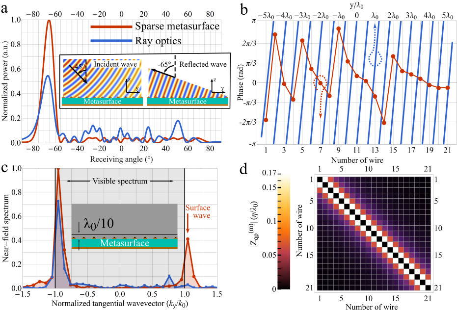
Numerical example. Since the majority of reconfigurable metasurfaces operates under the ray optics approach, in what follows we compare the efficiency of a sparse metasurface to that of a phase-gradient metasurface by considering a simple illustrative example. The sparse metasurface is represented by loaded wires equidistantly distributed along the top surface of a metal-backed dielectric substrate and the distance between two neighboring wires is ( being the free-space central operating wavelength), as illustrated in Figure 1a,b. In this example demonstrated by means of 2D full-wave simulations, the wires are modeled as hollow cylinders of radius with an electric surface current density boundary condition of . To compare wavefront transformation performances between the sparse metasurface and a phase-gradient metasurface, we implement an extreme example of anomalous reflection of . It is important to note that in conceptual studies, an incident wave is typically represented by a plane wave Asadchy et al. (2016); Mohammadi Estakhri and Alù (2016). In this work, we deal with a cylindrical wave illumination. Namely, the excitation is set as a TE-polarized cylindrical wave incident at and having the phase center away from the center of the metasurfaces, as shown in the inset of Figure 2a. Such configuration makes the separation between the specular reflection and the anomalously reflected wave equal to . Both classical phase-gradient and sparse metasurfaces are considered to be purely reactive. Ray optics approach suggests that the phase profile shown as the blue curve in Figure 2b should be established by the phase-gradient metasurface. The red dot markers in Figure 2b correspond to the fictitious local reflection coefficient calculated for the sparse metasurface according to the retrieval procedure described in the Supplementary Note 3. Since the red dots do not overlap with the blue curve, one can conclude that the approach of ray optics cannot be applied to design sparse metasurfaces. Figure 2a compares the scattering patterns created by the sparse metasurface (red curve) and the phase-gradient metasurface (blue curve). The classical metasurface exhibits strong spurious scattering in the far-field which makes the power scattered in the desired direction twice less than in case of the sparse metasurface. A key feature of sparse metasurfaces, allowing one to outperform gradient metasurfaces, is their strong non-locality. By extracting the scattered near-field at a distance above the sparse metasurface and performing discrete Fourier transform Oppenheim and Schafer (1989), a strong peak manifesting a surface wave is observed outside the visible part of the near-field spectrum (), as highlighted by the red trace in Figure 2c. Although the interaction between elements of the sparse metasurface decreases with distance and well localized, as shown in Figure 2d, the surface wave propagates along the whole metasurface, representing a collective effect. Conversely, the spectrum of the scattered near-field above the gradient metasurface (blue line in Figure 2c) does not exhibit any signature of surface waves.
Design. By gaining control over load-impedance densities of the wires, we are able to adjust the currents and manipulate the scattered field dynamically. In order to realize real-time control over load-impedance densities at microwave frequencies, we use a radio-frequency varactor diode where the capacitance can be tuned by an applied bias voltage. The schematic layout of the developed reconfigurable meta-atom is shown in Figure 1c. The design procedure was performed with the help of local periodic approximation recently established for periodic metagratings Popov et al. (2019b) since the conventional design methods of dense metasurfaces Epstein and Eleftheriades (2016c) are not applicable for sparse metasurfaces. Three principal parts of the elementary cell can be distinguished: a varactor loaded microstrip line (top), a microstrip line (middle), and a bias line (alongside). The microstrip lines together with the varactor diode form an equivalent parallel circuit. The middle microstrip line plays the role of an inductance that allows one to effectively decrease the minimal capacitance of the varactor diode and expand the dynamic range of accessible load-impedance densities without increasing the density of meta-atoms. The latter is extremely important when one tends to decrease the Ohmic losses of varactor diodes. The bias voltage is applied to the varactor diode through the metallized via connecting the top and bottom layers.
Similar to the theoretical example of anomalous reflection above, the experimental sample is composed of loaded wires, each represented by a chain of the designed meta-atoms, distributed along the surface of a metal-backed dielectric substrate, as shown in Figure 1a,b. Individual control of each wire in the metasurface is implemented by a bias network appearing behind the metal-backed substrate and powered by a multichannel DC voltage source. Once the metasurface is fabricated using printed circuit board technique and surface-mount component soldering (Figure 3a), it is characterized to establish the dependence of the load-impedance density upon the biasing voltage . The characterization procedure is described in the Methods and Supplementary Information. The measured load impedance density is plotted at GHz for different bias voltages in Figure 3b.

Dynamic far-field beam-forming. The experimental setup used to demonstrate the dynamic far-field manipulation capabilities of the proposed metasurface is schematically illustrated in Figure 3c. The sample and a feeding horn antenna are both placed on a rotating platform to be used as a transmitter and the radiation pattern is measured by a receiving horn antenna. The feeding horn placed at cm () away from the sample constitutes a cylindrical wave source, which makes it a very compact radiation system compared to generally exploited plane wave source. Other sources such as planar microstrip patch antenna can also be used in order to illuminate the sample and further reduce the profile of the system. In the first set of measurements, the incidence angle is set to in concordance with the numerical example above, and the operating frequency is fixed to GHz. Bias voltages for desired steering angles are found by means of the theoretical procedure described above and the experimental characterization of the sample detailed in Methods and Supplementary Note 4, and no further fine-tuning of voltages is required. Figure 3d demonstrates dynamic beam steering from up to , the corresponding bias voltages are also shown. The spurious scattering in the far-field region remains below 0.1, being well beyond limits of phase-gradient metasurfaces for large steering angles Asadchy et al. (2016); Mohammadi Estakhri and Alù (2016). As follows from the conclusions derived when analyzing Figure 2a,c, the efficient large-angle anomalous reflection serves as an indirect manifestation of a strong non-locality by the fabricated sparse reconfigurable metasurface. Even though we deal with a sparse metasurface, the employed design approach does not impose any restriction on the achievable beam-steering angle, which is in strong contrast with traditional periodic metasurface.
| Reference | № of elements | Frequency | Instantaneous | Incidence | Max. reflection | Level of | Total | Max. № |
| per area | range | bandwidth | angle | angle | side-lobes | absorption | of beams | |
| D. Sievenpiper et al. Sievenpiper et al. (2003) | 74–44 | 3.5-4.5 GHz | 8% | dB | for refl. angle | 1 | ||
| H. Yang et al. Yang et al. (2016) | 5 | 11.1 GHz | N/A | dB | N/A | 3 | ||
| B. Ratni et al. Ratni et al. (2018) | 31–21 | 9-11 GHz | N/A | dB | 1 | |||
| This work | 13–8 | 8.5-10 GHz | 5% | -10 dB at 10 GHz | at 10 GHz | |||
| -12.5 dB at 9.5 GHz | at 9.5 GHz |
The efficiency of beam-forming can be estimated more rigorously by calculating the scattering efficiency and the absorption of the sample. The former is found as the power in the desired beam divided by the total reflected power
| (3) |
where is the scattered power measured in the angle , angles and confine the main lobe. In Supplementary Note 6, we also compare the sample’s directivity to that of a uniform aperture of the same size, which serves as a standard reference. The scattering efficiency of the beam-steering functionality, displayed in Fig. 3d, lies in the range of 72% to 83%. The minimum efficiency corresponds to steering and the maximum one to steering. This little bit counter-intuitive result can be explained on the one hand by the relatively large beamwidth () in the case of . On the other hand, the level of side-lobes is the same for the beam-steering at and . It should also be noted that the scattering efficiency (3) of the non-periodic sparse metasurface cannot be directly compared to scattering efficiencies of metagratings reported in literature. Indeed, when estimating experimental scattering efficiency of a metagrating, one generally normalizes the power scattered in a desired diffraction order to the total power scattered in all diffraction orders Rabinovich et al. (2019). While a fabricated metagrating always has a finite size and therefore creates a continuous angular spectrum of the scattered field, such a procedure does not account for the power scattered in other directions apart from the diffraction orders represented by a finite set of Floquet modes. The absorbed energy by the sample can be estimated by normalizing the total power scattered from the sample to the one reflected from a metallic plate of the same dimensions (see Supplementary Note 6 for details)
| (4) |
In the examples demonstrated in Figure 3d, the absorption lies in the range from 40% () to 51% (). The main source of the absorption are the varactor diodes which are relatively lossy at GHz.
More complex examples of beam-forming are illustrated in Figure 3e under incidence, which demonstrates the ability to dynamically control the number of radiated beams and also highlights the metasurface’s agility with respect to the excitation. When applying successive sequence of pre-registered bias voltage profiles, one beam is firstly radiated at , then two symmetrical beams at and , and finally three beams centered around . Additional examples of beam-forming are demonstrated in Figure S7-S9 in the Supplementary Information. In all examples, the spurious scattering does not exceed the dB level. The high scattering efficiency of the sample is due to the rigorous theoretical model behind: we account for the mutual interactions between the elements, consider real-type excitation (non-planar incident wavefront in our specific case) and precisely solve the inverse scattering problem. The instantaneous operating bandwidth of the sample also depends on the configuration and reaches approximately %. On the other hand, the reconfigurability mechanism allows the sample to demonstrate frequency agility over a broad frequency range around centre frequency of GHz (%). The beamwidths are calculated assuming a level of side-lobes remaining below dB. The Supplementary Information provides additional details on the performances of the sample for beam-steering applications and on a much compact antenna system using a point source in close proximity of the sparse metasurface.

Table 1 allows one to compare the efficiency and functionalities of the reconfigurable sparse metasurface to traditional reconfigurable metasurfaces. From this comparison, it is clearly observed that the implemented mechanism of strong electromagnetic non-locality allows the reconfigurable sparse metasurface to outperform traditional designs, reach larger steering angles and effectively excite multiple beams. Furthermore, the levels of side-lobes and absorption are lower or similar to those of traditional metasurfaces demonstrating more modest functionality.
Adaptive near-field focusing. To further demonstrate the vast capabilities of the approach in manipulating fields, we study the flexibility and efficiency of the proposed reconfigurable metasurface for dynamic shaping of the near-field. Another experimental setup is mounted to measure the distribution of the electric field in front of the sample with a moving dielectric probe as sketched in Figure 4a. The EFS-105-12 fiber optic active antenna is used as field-sensing probe to measure both the amplitude and the phase of the electric field. It is composed of a purely dielectric head of 6.6 x 6.6 mm2 cross-section with negligible field perturbation pro . The sample is illuminated at normal incidence by a cylindrical wave radiated by a horn antenna, as illustrated by the corresponding measured electric field profile in Figure 4b. The processed experimental data are presented in Figures 4c, e and f. The processing procedure is described and compared to raw data in the Supplementary Note 7. In the first sequence of voltage settings, the sample acts as a high numerical aperture (NA) diffractive lens and focuses the incident wave at the distance as shown in Figure 4c. With the physical aperture of the sample being mm and the focal length of mm, the NA is approximately . The experimentally measured spot size being (corresponding FWHM is ), which is smaller (for the given NA) than the size of Airy spot establishing the diffraction limit Abbe (1873); Novotny and Hecht (2012), demonstrates subdiffraction focusing. Meanwhile, the minimum spot size of a subdiffraction focal spot is found to be Huang et al. (2018). The depth of focus (DOF), characterized as full width of the focal spot in the longitudinal direction at half maximum, is experimentally measured as , which agrees very well with the theoretical estimation Huang et al. (2018). The imaging and total efficiencies in this configuration are and , respectively. The level of secondary lobes is -8.5 dB. The imaging (total) efficiency is calculated as the reflected power in the focal spot divided over the total reflected (incident) power in the focal plane
| (5) |
| (6) |
where the coordinates and refer to the lateral limits of the focal spot and the coordinates and correspond to the lateral boundaries of the scanned region.
| Reference | № of elements | Frequency | Focal | FWHM () | Imaging | Total | Max. № |
| per area | length () | efficiency (%) | efficiency (%) | of spots | |||
| W. Zhu et al. Zhu et al. (2015) | 14 | 16 GHz | 5.1, 10, 15.2 | 2.1, 2.2, 2.5 | N/A | 10 | 1 |
| H.-X. Xu et al. Xu et al. (2016c) | 21 | 5.5 GHz | 0.83,1.38,1.65,2.20 | –,,,– | N/A | N/A | 1 |
| K. Chen et al. Chen et al. (2017) | 27 | 6.9 GHz | 1, 1.5, 2, 4 | N/A | N/A | 36 | 2 |
| B. Ratni et al. Ratni et al. (2020) | 31 | 9 GHz | 1.5, 2.25, 3 | 0.53, 0.6, 0.69 | 52, 56, 60 | 33, 40, 42 | 2 |
| This work | 8 at 10 GHz | 9.5 GHz | 1, 3 (Figs. 4c and e) | 0.43, 0.6 | 68, 78 | 21, 30 | |
| 10 GHz | 3 (Fig. 4f) | 0.6 | 88 | 57 |
Extracting the amplitude and phase of the electric field in the proximity of the sample allows us to directly observe surface waves manifesting strong non-locality. Performing discrete Fourier transform Oppenheim and Schafer (1989) on the measured electric field at the distance from the metasurface reveals two strong peaks outside the visible range (), as shown in Figure 4d. The peaks correspond to two surface waves propagating along the sample in opposite directions. The surface waves contribute to the aperture field and through the aperture field they are responsible for breaking the diffraction limit. However, being evanescent, the surface waves do not constitute the focal spot at distance from the sample. Indeed, the spectrum of the field in the focal plane consists in only propagating waves as shown in Figure S19 in the Supplementary Information. On the other hand, if one moves the focal spot closer to the metasurface, surface waves can be used to perform super-focusing and achieve the spot size much less than that of the subdiffraction limit (, ). As demonstrated in the Supplementary Information, to that end a denser, but still sparse, metasurface is required Popov et al. (2019a). In Figure S21-S24 an example of a sparse metasurface with the inter-wire distance of demonstrates focusing of the incident wave at focal length to the spot size of . In strong contrast to the phenomenon of super-oscillations Huang et al. (2018), which also allows to overcome the subdiffraction limit, the level of side-lobes remains very low due to the surface waves contributing significantly to the formation of the focal spot as revealed in the Supplementary Information.
By changing the applied voltage sequence and thus the load-impedance densities, one can move the focal spot further away from the sample and change the NA of the lens (from in Figure 4c to in Figure 4e). The spot size of (FWHM is ) is still smaller than the size of the corresponding Airy spot. Multiple subdiffraction focal spots can also be created and independently controlled (Figure 4f and Figure S16-S18 in the Supplementary Information), demonstrating the high efficiency and manipulation flexibility of the real-time reconfigurable metasurface. In Figure 4e,f, the measured DOF and its corresponding theoretical estimation is, respectively, and . At 9.5 GHz, for a single focal spot at distance (Figure 4e), the imaging and total efficiencies constitute, respectively, and . The increase of the total efficiency to (in comparison to for Figure 4c) is due to the lower level of side-lobes (-12 dB) and the higher imaging efficiency ( vs. ). The total (imaging) efficiency increases to () for two focal spots at 10 GHz displayed in Figure 4f. The difference between the total efficiencies at 9.5 and 10 GHz can be explained by different resonant behavior of the load-impedance density at these two frequencies, as it can be compared from Figures S6a and b. Indeed, when creating a single focal spot at 10 GHz (shown in Figure S18c in the Supplementary Information), the total efficiency also increases to and the imaging efficiency reaches .
Table 2 compares the focusing performances of the tested sample with those of conventional reconfigurable metasurfaces reported previously in literature. The comparison shows that the strong non-locality implemented in our reconfigurable metasurface allows achieving superior performances in terms of spot size and imaging efficiency for multiple functionalities. Furthermore, the total efficiency of the fabricated sparse metasurface can exceed those of traditional designs due to lower density of elements and operation outside resonance, where mainly capacitive response is required.
III Discussion and conclusion
In this work we have demonstrated implementation of the mechanism of strong electromagnetic non-locality in a reconfigurable sparse metasurface. The design procedure of such a metasurface has been described in details: from the theoretical model based on a numerical calculation of a Green’s function to the microscopic design of a unit cell incorporating a tunable element. It can be especially useful for implementation of reconfigurable metasurfaces at optical and visible frequencies where they suffer a lot from efficiency problems. Indeed, by reducing the density of meta-atoms and thus, complexity of the design and fabrication of a reconfigurable metasurface, one is actually able to outperform conventional metasurfaces, which often require more sophisticated design. Furthermore, the generality of the theoretical approach allows one to design conformal reconfigurable metasurfaces as well as planar ones.
As a direct endorsement of the proposed approach, a reconfigurable sparse metasurface loaded with controllable varactor diodes has been proposed to efficiently and dynamically manipulate fields in both near-field and far-field regions with an arbitrary incident wave illumination. Fundamentally, we have experimentally demonstrated direct and indirect evidences of surface waves propagating along the reconfigurable sparse metasurface manifesting its strongly non-local response. By comparing experimental performances of the fabricated sample to others reported previously in literature, we have demonstrated that the dynamic strongly non-local response allows to outperform conventional designs of reconfigurable metasurfaces in a broad range of functionalities both in near-field and far-field regions. As such, subdiffraction focusing, anomalous reflection at extreme angles, dynamic control of multiple beams and focal spots have been demonstrated. The ability of the proposed sparse metasurface to dynamically manipulate near- and far-fields in real-time paves the way to applications in reconfigurable devices such as lenses, antennas and imaging systems with superior performances.
Methods
Sample fabrication. The sample was fabricated by means of the conventional printed circuit board (PCB) technique and represents a six-layer sample with the bottom layer reserved for the bias network of the varactor diodes. Three woven-glass dielectric substrates F4BM220 (relative permittivity is , loss tangent is ) were used: one of mm thickness and two of mm thickness. Thickness of the copper cladding is m. Selected varactor diode (MAVR-011020-1411) has capacitance varying in the range from pF to pF. Metallic vias of mm radius are used to apply bias voltage to varactors.
Electronic control module. In order to control the fabricated sample, an electronic control module was developed upstream. It consists of a Raspberry Pi 3 B+, an ARM processor single board nano-computer, and a stack of two electronic cards integrating 16 independent DC voltage outputs each. The nano-computer is used as an operating unit for the two electronic cards and allows one to control the DC voltage of each of the 32 outputs from 0 to 30V. To facilitate the control, a human-machine interface in Python was developed. On the electronic side, each card is supplied with a fixed voltage of 30 V and operational amplifiers are used in a comparator assembly to control the voltage of each output. Each output is therefore controlled via the nano-computer using the SPI communication protocol.
Characterization. The aim of the experimental characterization of the sample is to establish the dependence between the applied bias voltage and the load-impedance density of the loaded wire comprising the sparse metasurface. A schematics and a photography of the experimental setup are shown respectively in Figure S5a,b in the Supplementary Information. We measure the frequency dependence of the complex amplitude of the specularly reflected wave from the sample as a function of the applied bias voltage. The same bias voltage is applied to all varactor diodes. The complex amplitude is normalized to the one measured from a metallic plate of the same size and thickness as the sample. The absolute value of the reflection coefficient is plotted in Figure S5c in the Supplementary Information. Then, we correlate the experimental frequency dependencies with the ones obtained via 3D full-wave numerical simulations of a unit cell (Figure 1c) with applied periodic boundary conditions, see Figure S5d in the Supplementary Information. In the simulations the varactor diode is modeled as a lumped RC-circuit with the impedance , where is the series resistance and is the capacitance. It is assumed that neither nor depend on the frequency. By comparing the positions of the experimental and theoretical resonances (Figure S5e in the Supplementary Information), we obtain the relation between the bias voltage and the varactor’s capacitance presented in Figure S5f in the Supplementary Information. Eventually, with known, we are able to find .
Data availability
The data that support the findings of this study are available from the authors on reasonable request.
Author contributions
V.P. and F.B. conceived the concept, V.P. developed the theory and the design methodology, performed numerical simulations, V.P., F.B. and S.N.B. carried out the design of the experimental samples, F.B. and S.N.B. oversaw the manufacture of the samples, B.R. participated in development of the multichannel voltage source used to power the reconfigurable sample, V.P. and B.R. performed experimental measurements. All the authors contributed to the interpretation of results and participated in the preparation of the manuscript.
Additional information
Supplementary Information accompanies this paper at [URL provided by the publisher].
Conflict of interests
The authors declare no competing financial interests.
References
- Sievenpiper et al. (2003) D. F. Sievenpiper, J. H. Schaffner, H. J. Song, R. Y. Loo, and G. Tangonan, “Two-dimensional beam steering using an electrically tunable impedance surface,” IEEE Transactions on Antennas and Propagation 51, 2713–2722 (2003).
- Lau and Hum (2012) J. Y. Lau and S. V. Hum, “Reconfigurable transmitarray design approaches for beamforming applications,” IEEE Transactions on Antennas and Propagation 60, 5679–5689 (2012).
- Clemente et al. (2013) A. Clemente, L. Dussopt, R. Sauleau, P. Potier, and P. Pouliguen, “Wideband 400-element electronically reconfigurable transmitarray in x band,” IEEE Transactions on Antennas and Propagation 61, 5017–5027 (2013).
- Zhu et al. (2014) B. O. Zhu, K. Chen, N. Jia, L. Sun, J. Zhao, T. Jiang, and Y. Feng, “Dynamic control of electromagnetic wave propagation with the equivalent principle inspired tunable metasurface,” Scientific reports 4, 1–7 (2014).
- Cui et al. (2014) T. J. Cui, M. Q. Qi, X. Wan, J. Zhao, and Q. Cheng, “Coding metamaterials, digital metamaterials and programmable metamaterials,” Light: Science & Applications 3, e218 (2014).
- Della Giovampaola and Engheta (2014) C. Della Giovampaola and N. Engheta, “Digital metamaterials,” Nature materials 13, 1115 (2014).
- Kaina et al. (2014) N. Kaina, M. Dupré, G. Lerosey, and M. Fink, “Shaping complex microwave fields in reverberating media with binary tunable metasurfaces,” Scientific reports 4, 1–8 (2014).
- Zhu et al. (2015) W. Zhu, Q. Song, L. Yan, W. Zhang, P-C. Wu, L. K. Chin, H. Cai, D. P. Tsai, Z. X. Shen, T. W. Deng, S. K. Ting, Y. Gu, G. Q. Lo, D. L. Kwong, Z. C. Yang, R. Huang, A-Q. Liu, and N. Zheludev, “A flat lens with tunable phase gradient by using random access reconfigurable metamaterial,” Advanced Materials 27, 4739–4743 (2015).
- Dupré et al. (2015) M. Dupré, P. del Hougne, M. Fink, F. Lemoult, and G. Lerosey, “Wave-field shaping in cavities: Waves trapped in a box with controllable boundaries,” Phys. Rev. Lett. 115, 017701 (2015).
- Xu et al. (2016a) H.-X. Xu, S. Sun, S. Tang, S. Ma, Q. He, G.-M. Wang, T. Cai, H.-P. Li, and L. Zhou, “Dynamical control on helicity of electromagnetic waves by tunable metasurfaces,” Scientific reports 6, 1–10 (2016a).
- Yang et al. (2016) H. Yang, X. Cao, F. Yang, J. Gao, S. Xu, M. Li, X. Chen, Y. Zhao, Y. Zheng, and S. Li, “A programmable metasurface with dynamic polarization, scattering and focusing control,” Scientific reports 6, 35692 (2016).
- Li et al. (2016) Y. B. Li, L. L. Li, B. B. Xu, W. Wu, R. Y. Wu, X. Wan, Q. Cheng, and T. J. Cui, “Transmission-type 2-bit programmable metasurface for single-sensor and single-frequency microwave imaging,” Scientific reports 6, 23731 (2016).
- Xu et al. (2016b) H.-X. Xu, S. Tang, S. Ma, W. Luo, T. Cai, S. Sun, Q. He, and L. Zhou, “Tunable microwave metasurfaces for high-performance operations: dispersion compensation and dynamical switch,” Scientific reports 6, 38255 (2016b).
- del Hougne et al. (2016) P. del Hougne, F. Lemoult, M. Fink, and G. Lerosey, “Spatiotemporal wave front shaping in a microwave cavity,” Phys. Rev. Lett. 117, 134302 (2016).
- Xu et al. (2016c) H.-X. Xu, S. Ma, W. Luo, T. Cai, S. Sun, Q. He, and L. Zhou, “Aberration-free and functionality-switchable meta-lenses based on tunable metasurfaces,” Applied Physics Letters 109, 193506 (2016c), https://doi.org/10.1063/1.4967438 .
- Chen et al. (2017) K. Chen, Y. Feng, F. Monticone, J. Zhao, B. Zhu, T. Jiang, L. Zhang, Y. Kim, X. Ding, S. Zhang, A. Alù, and C.-W. Qiu, “A reconfigurable active huygens’ metalens,” Advanced Materials 29, 1606422 (2017).
- Li et al. (2017) L. Li, T. J. Cui, W. Ji, S. Liu, J. Ding, X. Wan, Y. B. Li, M. Jiang, C.-W. Qiu, and S. Zhang, “Electromagnetic reprogrammable coding-metasurface holograms,” Nature communications 8, 1–7 (2017).
- Ratni et al. (2018) B. Ratni, A. de Lustrac, G.-P. Piau, and S. N. Burokur, “Reconfigurable meta-mirror for wavefronts control: applications to microwave antennas,” Opt. Express 26, 2613–2624 (2018).
- del Hougne et al. (2018) P. del Hougne, M. F Imani, T. Sleasman, J. N. Gollub, M. Fink, G. Lerosey, and D. R. Smith, “Dynamic metasurface aperture as smart around-the-corner motion detector,” Scientific reports 8, 1–10 (2018).
- Komar et al. (2018) A. Komar, R. Paniagua-Dominguez, A. Miroshnichenko, Y. F. Yu, Y. S. Kivshar, A. I. Kuznetsov, and D. Neshev, “Dynamic beam switching by liquid crystal tunable dielectric metasurfaces,” ACS Photonics 5, 1742–1748 (2018).
- del Hougne and Lerosey (2018) P. del Hougne and G. Lerosey, “Leveraging chaos for wave-based analog computation: Demonstration with indoor wireless communication signals,” Phys. Rev. X 8, 041037 (2018).
- Li et al. (2019) L. Li, Y. Shuang, Q. Ma, H. Li, H. Zhao, M. Wei, C. Liu, C. Hao, C.-W. Qiu, and T. J. Cui, “Intelligent metasurface imager and recognizer,” Light: Science & Applications 8, 1–9 (2019).
- Ma et al. (2019) Q. Ma, G. D. Bai, H. B. Jing, C. Yang, L. Li, and T. J. Cui, “Smart metasurface with self-adaptively reprogrammable functions,” Light: Science & Applications 8, 1–12 (2019).
- Liu et al. (2019) F. Liu, O. Tsilipakos, A. Pitilakis, A. C. Tasolamprou, M. S. Mirmoosa, N. V. Kantartzis, D-H. Kwon, J. Georgiou, K. Kossifos, M. A. Antoniades, M. Kafesaki, C. M. Soukoulis, and S. A. Tretyakov, “Intelligent metasurfaces with continuously tunable local surface impedance for multiple reconfigurable functions,” Phys. Rev. Applied 11, 044024 (2019).
- del Hougne et al. (2019) P. del Hougne, M. Fink, and G. Lerosey, “Optimally diverse communication channels in disordered environments with tuned randomness,” Nature Electronics 2, 36–41 (2019).
- Leitis et al. (2020) A. Leitis, A. Heßler, S. Wahl, M. Wuttig, T. Taubner, A. Tittl, and H. Altug, “All-dielectric programmable huygens’ metasurfaces,” Advanced Functional Materials , 1910259 (2020).
- Ratni et al. (2020) B. Ratni, Z. Wang, K. Zhang, X. Ding, A. de Lustrac, G.-P. Piau, and S. N. Burokur, “Dynamically controlling spatial energy distribution with a holographic metamirror for adaptive focusing,” Phys. Rev. Applied 13, 034006 (2020).
- Hadad et al. (2015) Y. Hadad, D. L. Sounas, and A. Alù, “Space-time gradient metasurfaces,” Phys. Rev. B 92, 100304 (2015).
- Zhao et al. (2018) J. Zhao, X. Yang, J. Y. Dai, Q. Cheng, X. Li, N. H. Qi, J. C. Ke, G. D. Bai, S. Liu, S. Jin, A. Alù, and T. J. Cui, “Programmable time-domain digital-coding metasurface for non-linear harmonic manipulation and new wireless communication systems,” National Science Review 6, 231–238 (2018).
- Zhang et al. (2018) L. Zhang, X. Q. Chen, S. Liu, Q. Zhang, J. Zhao, J. Y. Dai, G. D. Bai, X. Wan, Q. Cheng, G. Castaldi, V. Galdi, and T. J. Cui, “Space-time-coding digital metasurfaces,” Nature communications 9, 1–11 (2018).
- Liu et al. (2018) M. Liu, D. A. Powell, Y. Zarate, and I. V. Shadrivov, “Huygens’ metadevices for parametric waves,” Phys. Rev. X 8, 031077 (2018).
- Salary et al. (2018) M. M. Salary, S. Jafar-Zanjani, and H. Mosallaei, “Electrically tunable harmonics in time-modulated metasurfaces for wavefront engineering,” New Journal of Physics 20, 123023 (2018).
- Caloz et al. (2018) C. Caloz, A. Alù, S. Tretyakov, D. Sounas, K. Achouri, and Z.-L. Deck-Léger, “Electromagnetic nonreciprocity,” Phys. Rev. Applied 10, 047001 (2018).
- Zang et al. (2019a) J.W. Zang, D. Correas-Serrano, J.T.S. Do, X. Liu, A. Alvarez-Melcon, and J.S. Gomez-Diaz, “Nonreciprocal wavefront engineering with time-modulated gradient metasurfaces,” Phys. Rev. Applied 11, 054054 (2019a).
- Zang et al. (2019b) J.W. Zang, A. Alvarez-Melcon, and J.S. Gomez-Diaz, “Nonreciprocal phased-array antennas,” Phys. Rev. Applied 12, 054008 (2019b).
- Mirmoosa et al. (2019) M.S. Mirmoosa, G.A. Ptitcyn, V.S. Asadchy, and S.A. Tretyakov, “Time-varying reactive elements for extreme accumulation of electromagnetic energy,” Phys. Rev. Applied 11, 014024 (2019).
- Ptitcyn et al. (2019) G. Ptitcyn, M. S. Mirmoosa, and S. A. Tretyakov, “Time-modulated meta-atoms,” Phys. Rev. Research 1, 023014 (2019).
- Wang et al. (2016) Q. Wang, E. T.F. Rogers, B. Gholipour, C-M. Wang, G. Yuan, J. Teng, and N. I. Zheludev, “Optically reconfigurable metasurfaces and photonic devices based on phase change materials,” Nature Photonics 10, 60 (2016).
- Huang et al. (2016) Y.-W. Huang, H. W. H. Lee, R. Sokhoyan, R. A. Pala, K. Thyagarajan, S. Han, D. P. Tsai, and H. A. Atwater, “Gate-tunable conducting oxide metasurfaces,” Nano letters 16, 5319–5325 (2016).
- Cui et al. (2019) T. Cui, B. Bai, and H.-B. Sun, “Tunable metasurfaces based on active materials,” Advanced Functional Materials 29, 1806692 (2019).
- He et al. (2019) Q. He, S. Sun, and L. Zhou, “Tunable/reconfigurable metasurfaces: Physics and applications,” Research 2019, 1849272 (2019).
- Pfeiffer and Grbic (2013) C. Pfeiffer and A. Grbic, “Metamaterial huygens’ surfaces: Tailoring wave fronts with reflectionless sheets,” Phys. Rev. Lett. 110, 197401 (2013).
- Epstein and Eleftheriades (2014) A. Epstein and G. V. Eleftheriades, “Passive lossless huygens metasurfaces for conversion of arbitrary source field to directive radiation,” IEEE Transactions on Antennas and Propagation 62, 5680–5695 (2014).
- Epstein et al. (2016) A. Epstein, J. P. S. Wong, and G. V. Eleftheriades, “Cavity-excited huygens’ metasurface antennas for near-unity aperture illumination efficiency from arbitrarily large apertures,” Nature communications 7, 10360 (2016).
- Asadchy et al. (2016) V. S. Asadchy, M. Albooyeh, S. N. Tcvetkova, A. Díaz-Rubio, Y. Ra’di, and S. A. Tretyakov, “Perfect control of reflection and refraction using spatially dispersive metasurfaces,” Phys. Rev. B 94, 075142 (2016).
- Epstein and Eleftheriades (2016a) A. Epstein and G. V. Eleftheriades, “Arbitrary power-conserving field transformations with passive lossless omega-type bianisotropic metasurfaces,” IEEE Transactions on Antennas and Propagation 64, 3880–3895 (2016a).
- Epstein and Eleftheriades (2016b) A. Epstein and G. V. Eleftheriades, “Synthesis of passive lossless metasurfaces using auxiliary fields for reflectionless beam splitting and perfect reflection,” Phys. Rev. Lett. 117, 256103 (2016b).
- Mohammadi Estakhri and Alù (2016) N. Mohammadi Estakhri and A. Alù, “Wave-front transformation with gradient metasurfaces,” Phys. Rev. X 6, 041008 (2016).
- Kuester et al. (2003) E. F. Kuester, M. A. Mohamed, M. Piket-May, and C. L. Holloway, “Averaged transition conditions for electromagnetic fields at a metafilm,” IEEE Transactions on Antennas and Propagation 51, 2641–2651 (2003).
- Epstein and Eleftheriades (2016c) A. Epstein and G. V. Eleftheriades, “Huygens’ metasurfaces via the equivalence principle: design and applications,” J. Opt. Soc. Am. B 33, A31–A50 (2016c).
- Díaz-Rubio et al. (2017) A. Díaz-Rubio, V. S. Asadchy, A. Elsakka, and S. A. Tretyakov, “From the generalized reflection law to the realization of perfect anomalous reflectors,” Science Advances 3 (2017), 10.1126/sciadv.1602714.
- Kwon (2018) D. Kwon, “Lossless scalar metasurfaces for anomalous reflection based on efficient surface field optimization,” IEEE Antennas and Wireless Propagation Letters 17, 1149–1152 (2018).
- Ra’di et al. (2017) Y. Ra’di, D. L. Sounas, and A. Alù, “Metagratings: Beyond the limits of graded metasurfaces for wave front control,” Phys. Rev. Lett. 119, 067404 (2017).
- Epstein and Rabinovich (2017) A. Epstein and O. Rabinovich, “Unveiling the properties of metagratings via a detailed analytical model for synthesis and analysis,” Phys. Rev. Applied 8, 054037 (2017).
- Popov et al. (2019a) V. Popov, F. Boust, and S. N. Burokur, “Constructing the near field and far field with reactive metagratings: Study on the degrees of freedom,” Phys. Rev. Applied 11, 024074 (2019a).
- Wong and Eleftheriades (2018) A. M. H. Wong and G. V. Eleftheriades, “Perfect anomalous reflection with a bipartite huygens’ metasurface,” Phys. Rev. X 8, 011036 (2018).
- Popov et al. (2018) V. Popov, F. Boust, and S. N. Burokur, “Controlling diffraction patterns with metagratings,” Phys. Rev. Applied 10, 011002 (2018).
- Popov et al. (2020) V. Popov, S. N. Burokur, and F. Boust, “Conformal sparse metasurfaces for wavefront manipulation,” (2020), arXiv:2001.09878 [physics.app-ph] .
- Kennedy and Eberhart (1995) J. Kennedy and R. Eberhart, “Particle swarm optimization,” in Proceedings of ICNN’95 - International Conference on Neural Networks, Vol. 4 (1995) pp. 1942–1948 vol.4.
- Oppenheim and Schafer (1989) A. V. Oppenheim and R. W. Schafer, Discrete-time Signal Processing (Prentice-Hall, Inc., Upper Saddle River, NJ, USA, 1989).
- Popov et al. (2019b) V. Popov, M. Yakovleva, F. Boust, J-L. Pelouard, F. Pardo, and S. N. Burokur, “Designing metagratings via local periodic approximation: From microwaves to infrared,” Phys. Rev. Applied 11, 044054 (2019b).
- Rabinovich et al. (2019) O. Rabinovich, I. Kaplon, J. Reis, and A. Epstein, “Experimental demonstration and in-depth investigation of analytically designed anomalous reflection metagratings,” Phys. Rev. B 99, 125101 (2019).
- (63) For further details on the EFS-105-12 fiber optic probe: http://www.enprobe.de/products.htm.
- Abbe (1873) E. Abbe, “Beiträge zur theorie des mikroskops und der mikroskopischen wahrnehmung,” Archiv für mikroskopische Anatomie 9, 413–418 (1873).
- Novotny and Hecht (2012) L. Novotny and B. Hecht, Principles of nano-optics (Cambridge university press, 2012).
- Huang et al. (2018) K. Huang, F. Qin, H. Liu, H. Ye, C-W. Qiu, M. Hong, B. Luk’yanchuk, and J. Teng, “Planar diffractive lenses: Fundamentals, functionalities, and applications,” Advanced Materials 30, 1704556 (2018).