Beamforming Design for Multiuser Transmission Through Reconfigurable Intelligent Surface
Abstract
This paper investigates the problem of resource allocation for multiuser communication networks with a reconfigurable intelligent surface (RIS)-assisted wireless transmitter. In this network, the sum transmit power of the network is minimized by controlling the phase beamforming of the RIS and transmit power of the BS. This problem is posed as a joint optimization problem of transmit power and RIS control, whose goal is to minimize the sum transmit power under signal-to-interference-plus-noise ratio (SINR) constraints of the users. To solve this problem, a dual method is proposed, where the dual problem is obtained as a semidefinite programming problem. After solving the dual problem, the phase beamforming of the RIS is obtained in the closed form, while the optimal transmit power is obtained by using the standard interference function. Simulation results show that the proposed scheme can reduce up to 94% and 27% sum transmit power compared to the maximum ratio transmission (MRT) beamforming and zero-forcing (ZF) beamforming techniques, respectively.
Index Terms:
Resource allocation, power minimization, reconfigurable intelligent surface, phase shift optimization, semidefinite programming, beamforming design.I Introduction
Driven by the rapid development of advanced multimedia applications, it is urgent for the next-generation wireless network to support high spectral efficiency and massive connectivity [1]. Due to the demand of high data rate and serving a massive number of users, energy consumption has become a challenging problem in the design of the future wireless network [2, 3, 4, 5, 6].
Recently, reconfigurable intelligent surface (RIS)-assisted wireless communication has been proposed as a potential solution for enhancing the energy efficiency of wireless networks [7, 8, 9, 10, 11, 12, 13, 14, 15, 16]. RIS is a new paradigm that can flexibly manipulate electromagnetic (EM) waves. Researches of RIS-assisted wireless communications mainly follow into two aspects: RIS as a passive reflector and RIS as an active transceiver.
On one hand, RIS can serve as a passive reflector. An RIS is a meta-surface equipped with low-cost and passive elements that can be programmed to turn wireless channels into a partially deterministic space. In RIS-assisted wireless communication systems, a base station (BS) sends control signals to an RIS controller so as to optimize the properties of incident waves and improve the communication quality of users [17, 18, 19]. The RIS acting as a reflector does not perform any decoding or digitalization operation. Hence, if properly deployed, the RIS promises much lower energy consumption than traditional amplify-and-forward (AF) relays [20, 21, 22, 23, 24, 25, 26, 27]. A number of existing works such as in [28, 29, 9, 30, 31, 32, 33, 34, 35, 36] have studied to optimize the deployment of RISs in wireless networks. In [28], the downlink sum-rate of an RIS-assisted wireless communication system was characterized. Asymptotic analysis of uplink data rate in an RIS-based large antenna-array system was presented in [29]. Considering energy harvesting, an RIS was invoked for enhancing the sum-rate performance of a system with simultaneous wireless information and power transfer [9]. Instead of considering the availability of instantaneous channel state information (CSI), the authors in [30] proposed a two-time-scale transmission protocol to maximize the average achievable sum-rate for an RIS-aided multiuser system under a general correlated Rician channel model. Taking the secrecy into consideration, the work in [31] investigated the problem of secrecy rate maximization of an RIS-assisted multi-antenna system. Further considering imperfect CSI, the physical layer security was enhanced by an RIS in a wireless channel [32]. Beyond the above studies, the use of RISs for enhanced wireless energy efficiency has been studied in [37]. In [37], authors proposed a new approach to maximize the energy efficiency of a multiuser multiple-input single-output (MISO) system by jointly controlling the transmit power of the BS and the phase shifts of the RIS. The RIS-assisted simultaneous wireless information and power transfer (SWIPT) system was studied in [33], where the sum transmit power at the BS was minimized via jointly optimizing its transmit precoders and the reflect phase shifts at all RISs, subject to the quality-of-service (QoS) constraints at all users. The authors in [34] studied the resource allocation design for secure communication in RIS-assisted multiuser MISO communication systems by using artificial noise (AN). Considering both security and SWIPT, the energy efficiency maximization problem was studied in [35] for the secure RIS-aided SWIPT. For spectrum sensing, an RIS-assisted cognitive radio system was investigated in [36], where an RIS is deployed to assist in the spectrum sharing between a primary user link and a secondary user link.
On the other hand, the RIS-assisted wireless transmitter [38, 39, 40, 41, 42, 43] can directly perform modulation on the EM carrier signals, without the need for conventional radio-frequency (RF) chains, which can be used for holographic multiuser multiple-input multiple-output (MIMO) technologies. In [39], authors investigated the RIS-based quadrature phase shift keying (QPSK) transmission over wireless channels. The RIS-based 8-phase shift keying (8PSK) was further studied in [40]. The feasibility of using RIS for MIMO with higher-order modulations was studied in [43], which presented an analytical modelling of the RIS-based system. However, the above works [38, 39, 40, 41, 42, 43] only considered the RIS-assisted wireless transmitter for single-user cases. In this paper, we investigate the beamforming design for multiuser transmission with the RIS-assisted wireless transmitter. The main contributions of this paper include:
-
•
We consider a downlink wireless communication system with one RIS-assisted wireless transmitter and multiple users. To minimize the sum transmit power of the BS, we jointly optimize phase shifts of the RIS and the multiuser power allocation at the BS. We formulate an optimization problem with the objective of minimizing the sum transmit power under individual user constraints in terms of signal-to-interference-plus-noise ratio (SINR) and unit-modulus constraint of the RIS phase shifts.
-
•
To minimize the sum transmit power of the BS, a dual method is proposed. By using the dual method, the dual problem of the sum transmit power minimization problem is first obtained. Then, phase shifts of the RIS can be obtained in the closed form. For the transmit power of the BS, an iterative power control scheme based on the standard interference function is proposed to obtain the optimal power control.
-
•
We consider both maximum ratio transmission (MRT) beamforming and zero-forcing (ZF) beamforming techniques when solving the sum transmit power minimization problem. The power scaling law performance of the multiuser communication is evaluated for the RIS-assisted wireless transmitter. Simulation results show that the proposed method saves up to 94% and 27% sum transmit power compared to the conventional MRT and ZF schemes, respectively.
The rest of this paper is organized as follows. System model and problem formulation are described in Section II. Section III provides the algorithm design. Simulation results are presented in Section IV. Conclusions are drawn in Section V.
Notations: In this paper, the imaginary unit of a complex number is denoted by . Matrices and vectors are denoted by boldface capital and lower-case letters, respectively. Matrix denotes a diagonal matrix whose diagonal components are . The real part of a complex number is denoted by . indicates that is a positive semidefinite matrix. , , and respectively denote the conjugate, transpose, and conjugate transpose of vector . and denote the -th and -th elements of the respective vector and matrix . stands for the module of a complex number , while denotes the -norm of vector . The identity matrix is denoted by , while an all-one vector is denoted by . The distribution of a circularly symmetric complex Gaussian variable with mean and covariance is denoted by . The expectation operation is denoted by . denotes the Moore-Penrose pseudoinverse of matrix . The optimal value of an optimization variable is denoted by .
II System Model and Problem Formulation
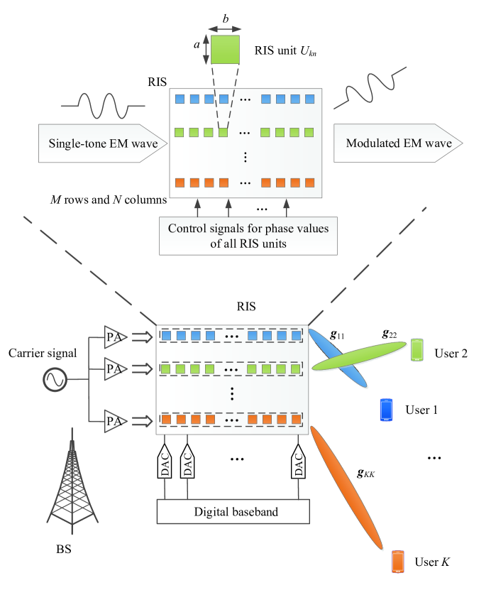
Consider an RIS-assisted multiuser wireless communication system that consists of one BS with a single antenna, an RIS, and a set of users. The RIS consists of rows and columns of RIS units, while each user is equipped with one antenna. The RIS unit in the -th row and -th column is denoted by .
II-A RIS-Assisted Modulation
RIS is indeed a programmable metasurface composed of sub-wavelength units, which can manipulate EM waves. All RIS units are regularly arranged in a two-dimensional structure, as shown in Fig. 1. The length and width of each RIS unit are denoted by and , respectively. The control signal of each RIS unit can change the electrical parameter of the tunable component, such as the phase [43].
Let and denote the incident and reflecting EM waves on RIS unit , respectively. Following the definition of reflection phase of an EM, say as the reflection phase of RIS unit , it follows:
| (1) |
In particular, if the incident EM wave is a single-tone EM wave (i.e., a carrier signal) with frequency and amplitude , equation (1) can be further expressed by:
| (2) |
From (2), it can be observed that the adjustable phase can achieve a phase modulation on the carrier signal, which is referred to as the RIS-assisted modulation.
II-B RIS-Assisted Multiuser Communication
An RIS-assisted multiuser wireless communication system111In system model, the authors in [44] considered RIS as a passive relay, while RIS is used as a passive transmitter in this paper. Due to this difference, the mathematical signal model in this paper is different from [44]. is illustrated in Fig. 1 [39, 43]. The reflection phase of each RIS unit is controlled by the digital baseband through the digital-to-analog converters (DACs), i.e., each RIS unit is controlled by one dedicated DAC. Before the carrier signal is reflected to each row of the RIS units, one narrow-band power amplifier (PA) is used to control the power of the carrier signal and the energy flux density on each RIS unit in the -th row is denoted as . The number of PAs equal to the number of served users. Note that in the considered system, the information is actually embedded in the phase control signals of each row of the RIS. As shown in Fig. 1, RIS is not connected with the digital baseband directly and RIS is used to reflect the baseband signal.
Compared to the traditional hybrid mmWave system, the differences of the current RIS-transmitter setup include:
-
1.
Transmit antenna: There are multiple transmit antennas in the traditional hybrid mmWave system, while only one transmit antenna is needed for the RIS-assisted wireless transmitter system in this paper.
-
2.
Modulation: For the traditional hybrid mmWave system, the signals are modulated in multiple antennas before the baseband precoder. The RIS-assisted wireless transmitter can directly perform modulation on the EM carrier signals, i.e., continuous phase modulation scheme is adopted.
-
3.
RF chain: For the traditional hybrid mmWave system, multiple RF chains are needed. In contrast, the proposed RIS-assisted wireless transmitter is considered as an RF chain-free transmitter.
To construct the multiple data streams for multiple users, the units in the -th row of the RIS are allocated to user 222In this paper, the RIS unit allocation for each user is assumed to be fixed for the convenience of deployment, i.e., ., i.e., the phases of RIS units are used to modulate the transmitted signal for user . Let the transmitted signal for user be:
| (3) |
Through changing the value of , signal can be modulated by phase shift-keying (PSK). In [43], it was shown that quadrature amplitude modulation (QAM) can also by achieved by equation (3) of proper designs. As a result, the transmitted signal by the RIS units can be presented by:
| (4) |
where . For notational simplicity, we introduce:
| (5) |
and equation (II-B) can be rewritten as
| (6) |
where is the phase beamformer of user which can be adjusted by the RIS.
Assume that the carrier signal with frequency is a uniform plane wave. In consequence, the transmitted signal at the BS is
| (7) |
where is the transmit power of the BS for user . Equation (7) is a mathematical signal model.
Since the source is close to the RIS, as shown in Fig. 1, the channel from the source to the RIS can be precisely measured, which can be regarded as a constant as in [43]. The received signal at user can be given by:
| (8) |
where is the channel gain from all RIS elements to user , is the channel gain from RIS elements in the -th row to user , and is the additive white Gaussian noise. Assume that the signals are only reflected by the RIS once. Since both the phase and transmit power can be changed, we can construct that the input term follows the Gaussian distribution, and the channel capacity can be achieved. Based on this consideration on (8), the SINR at user is
| (9) |
Note that the required CSI for the proposed RIS-assisted wireless transmitter only includes channel gains from the BS (i.e., RIS) to users. In contrast, for the conventional RIS-assisted wireless transmission where the RIS acts as a passive reflector, the required CSI includes channel gains from the BS to the RIS, the RIS to users, and the BS to users. As a result, compared to the conventional RIS-assisted wireless transmission, one key novelty of the proposed RIS-assisted wireless transmitter is that the required amount of CSI is smaller. There are already many significant methods that are proposed in existing works for obtaining CSI in RIS-based communication systems. For example, the works [45] and [46] presented compressive sensing and deep learning approaches for recovering the involved channels and designing the RIS phase matrix. Based on the parallel factor framework, the authors in [47] proposed an alternating least square method, which continuously estimates the all channels without too high complexity.
II-C Problem Formulation
Given the considered system model, our objective is to jointly optimize the phase beamforming and transmit power so as to minimize the sum transmit power under individual minimum SINR requirements. Mathematically, the problem for the RIS-assisted multiuser transmission can be formulated as:
| (10) | ||||
| s.t. | (10a) | |||
| (10b) | ||||
where , , , and is the minimum SINR requirement of user . The minimum SINR constraints for all users are given in (10a), and (10b) presents the unit-modulus constraints. Different from the conventional RF beamforming design, the phase beamforming problem (10) introduces the unique unit-modulus constraints (10b). Due to the nonconvex constraints in (10b), the problem (10) is nonconvex.
III Algorithm Design
To solve the nonconvex problem in (10), the dual method is first applied, where the dual problem of (10) is always a convex problem, which can be effectively solved. For comparisons, two conventional techniques, MRT beamforming and ZF beamforming, are also provided to solve the problem (10).
III-A Dual Method
To rewrite sum power minimization problem (10) in a simplifier manner, we introduce . Replacing with , the problem (10) is equivalent to:
| (11) | ||||
| s.t. | (11a) | |||
| (11b) | ||||
where .
Denote and we define the following time-sharing condition.
Definition 1
The time-sharing condition has the following intuitive interpretation. Consider the maximum value of the optimization problem (11) as a function of the constraint . Clearly, a smaller implies a more relaxed constraint. So, roughly speaking, the maximum value is an increasing function of . The time-sharing condition implies that the maximum value of the optimization problem is a concave function of . To show the gap between problem (11) and its dual problem, we provide the following lemma.
Lemma 1
The duality gap for multiuser RIS-assisted optimization (11) always tends to zero as the number of users or the number of RIS unit elements goes to infinity, regardless of whether the original problem is convex.
Proof: This result holds by directly applying Theorems 1 and 2 in [48]. According to [48, Theorem 2], the time-sharing property holds for all optimization problems with infinite channel gains, i.e., or . Based on [48, Theorem 1], the optimization problem has a zero duality gap If it satisfies the time-sharing property.
According to Lemma 1, the near optimal solution of problem (11) can be obtained by solving its dual problem if the number of users is high or the number of RIS units is large. In practice, for example, since RIS unit is low-cost, a large number of RIS units can be deployed at the BS. Consequently, the sum power minimization problem (11) can be effectively solved via its dual problem.
Theorem 1
Proof: The Lagrangian function for the optimization problem (11) is given by:
| (13) |
Denoting
| (14) |
we can rewrite Lagrangian function (III-A) by:
| (15) |
The dual objective can be given by [49]:
| (16) |
Since must be positive and there are no constraints on the beamforming , we have if or is not positive semidefinite.
Due to the fact that and should be selected that the dual objective is finite. As a result, constraints that and is positive semidefinite should be satisfied. Formally, the Lagrangian dual problem can be stated as (12).
Since the objective is linear and the constraints are either linear or linear matrix inequalities, dual problem (12) is a semidefinite programming (SDP) problem, which can be solved by using the standard CVX toolbox [50, 51]. Having obtained the dual variables by solving dual problem (12), it remains to obtain the optimal beamforming and transmit power . To find the optimal , we calculate the gradient of the Lagrangian function for problem (11) with respect to and set it to zero:
| (17) |
Based on (17), we have:
| (18) |
Solving equation (18) yields:
| (19) |
Since is a scalar, the optimal has the following expression:
| (20) |
where
| (21) |
Note that the -norm of phase vector is since the module of each element in phase vector is unit. To obtain the value of power , we find that the minimum SINR constraints (11a) must hold with equality for all users at the optimum solution. Substituting (20) into SINR constraints (11a) and setting them with equality, we can obtain:
| (22) |
By using the concept of standard interference function, equation (22) can be written in the following form:
| (23) |
where and
| (24) |
By checking the positivity, monotonicity, and scalability properties, we can prove that function is always a standard interference function [52], which allows us to use the iterative power control scheme to solve equation (23). The iterative power control scheme is given by:
| (25) |
where the superscript means the value of the variable in the -th iteration. According to [52, Theorem 2], the iterative power control scheme (25) always converges to the unique fixed point if (23) is feasible.
The dual method for solving problem (12) is summarized in Algorithm 1. Since the duality gap is zero for the large number of RIS units, the solution obtained by the dual method in Algorithm 1 is the optimal solution of the original problem in (11).
III-B SDR Approach
In this section, we apply the semidefinite relaxation (SDR) technique to solve problem (11). We introduce matrix , which needs to satisfy and the rank of is one. As a result, problem (11) is equivalent to
| (26) | ||||
| s.t. | (26a) | |||
| (26b) | ||||
| (26c) | ||||
| (26d) | ||||
where . However. (26) is still a nonconvex problem due to the nonconvex rank-one constraint (26c). We apply SDR to relax this rank-one constraint and problem (26) can be represented as:
| (27) | ||||
| s.t. | (27a) | |||
| (27b) | ||||
| (27c) | ||||
Problem (27) is a standard convex problem, which can be solved by existing toolboxes such as CVX. Since the rank-one constraint is relaxed, the solution of problem (27) is not necessarily to the optimal solution of the original problem (27), which implies that the optimal objective value of problem (27) only serves an upper bound of problem (26). Thus, we can use the method in [53] to construct a rank-one solution from the obtained higher-rank solution to problem (26).
According to [54], the SDR approach followed by a sufficiently large number of randomizations guarantees at least a -approximation of the optimal objective value of problem (26). Since constructing a feasible rank-one solution requires a lot of randomizations, the complexity of the SDR approach is higher than the proposed dual method. Besides, the proposed dual method can be guaranteed to be the optimal for large number of users or RIS unit elements.
III-C MRT and ZF Beamforming
To solve the sum power minimization problem (10) in the conventional ways, we provide the MRT and ZF beamforming methods. Note that the optimal power control can be obtained by using the iterative power control scheme (25), this section only provides the method of optimizing the phase beamforming .
III-C1 MRT beamforming
In MRT beamforming, the beamforming is designed such that the received signal at each user is maximized. Mathematically, the MRT beamforming problem is formulated as:
| (28) | ||||
| s.t. | (28a) | |||
To solve problem (28), the MRT beamforming can be expressed as:
| (29) |
From (29), we can see that the optimal phase vector should be tuned such that the signal that passes through all RIS units is aligned to be a signal vector with the equal phase at each element, i.e., is a real number for all .
III-C2 ZF bemaforming
The idea of ZF beamforming is to invert the channel matrix at the transmitter in order to create orthogonal channels between the BS and users. The ZF beamforming problem can be formulated as:
| (30) | ||||
| s.t. | (30a) | |||
| (30b) | ||||
Due to the nonconvex unit-modulus constraints (30b), the conventional ZF method cannot be directly applied. With new nonconvex constraints (30b), it is of importance to investigate the feasibility of (30). For the feasibility of problem (30), we have the following lemma.
Lemma 2
Problem (30) is feasible only if the following constraints are satisfied:
| (31) |
Proof: According to constraints (30a), we have:
| (32) |
Taking the absolute value at both sides yields:
| (33) |
Further combining constraints (30b), we have:
| (34) |
where the inequality follows from the triangle inequality. Adding on both sides, (34) becomes:
| (35) |
Since inequality (35) should be satisfied for any , conditions (31) are obtained by using the operation on both sides of (35).
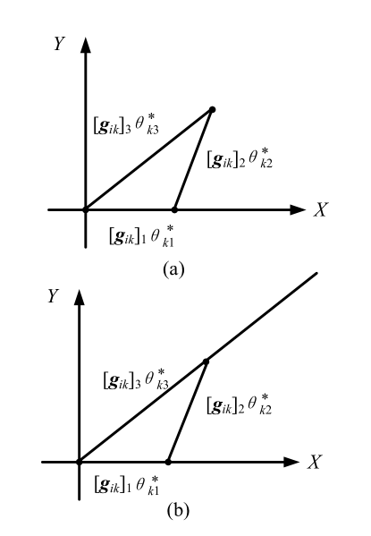
To elaborate lemma 2 further, an example of and is shown in Fig. 2. In this figure, we consider the special case that there are reflecting elements and the channel gain with the maximum amplitude is . If the condition (31) is satisfied, we have
i.e.,
as shown in Fig. 2(a). In this case, we can always construct a triangle with the length of three edges are respectively , , and , which means that there always exists such that . However, if the condition (31) is not satisfied, i.e., , as shown in Fig. 2(b). In this case, we cannot construct a triangle with the length of three edges that are respectively , , and . As a result, there is no solution for equation .
After checking the feasibility, we find that ZF beamforming problem (30) is still difficult to solve (i.e., it is nonconvex) because of nonconvex constraints (30b). In the following, an iterative algorithm is proposed to effectively solve ZF beamforming problem (30) with low complexity.
Without loss of generality, the term in the objective function (30) can be expressed as a real number through an arbitrary rotation to phase beamforming . As a result, the objective function (30) can be equivalent to
| (36) |
According to constraint (30a), must lie in the orthogonal complement of the subspace and the orthogonal projector matrix on this orthogonal complement is [55]
| (37) |
where
| (38) |
For any vector satisfying constraint (30a), can be expressed by:
| (39) |
where is an complex vector to be optimized.
Based on (36) and (39), ZF beamforming optimization problem (30) is equivalent to:
| (40) | ||||
| s.t. | (40a) | |||
| (40b) | ||||
Since both variables and are coupled in the constraint (40a), we introduce the barrier method to transform problem (40) as follows
| (41) | ||||
| s.t. | (41a) | |||
where is a large penalty factor [49]. To solve problem (41), an iterative algorithm is proposed via alternatingly optimizing with fixed , and updating with optimized in the previous step, which admits efficient closed-form solutions in each step.
In the first step, given , problem (41) can be formulated as:
| (42) | ||||
| s.t. | (42a) | |||
To maximize (42), it is easy to get
| (43) |
In the second step, we update the value of with the optimized in (43). Then, problem (41) becomes
| (44) | ||||
Problem (44) is convex and thus the optimal solution can be obtained by setting the gradient to zero. We calculate the gradient of (44) with respect to and set it to zero, i.e.,
| (45) |
which gives
| (46) |
Note that the iterative algorithm for solving problem (41) is summarized in Algorithm 2. Due to the fact that the optimal solution of problem (42) and (44) can be obtained, the objective value (41) is always increasing at each iteration. Since the objective value of problem (41) is increasing at each iteration and the objective value of problem (41) always has a finite upper bound, Algorithm 2 always converges.
III-D Power Scaling Law with Infinite RIS Units
We characterize the scaling law of the average received power at the user with respect to the number of RIS units, i.e., . For simplicity, we consider the single-user case with . The received power at the user is , where is the transmitted power at the BS, is the channel gain between the RIS and the user, and is the phase beamfoming of the BS. We compare two phase beamforming solutions: (i) and (ii) the MRT beamforming .
Theorem 2
Assume that . If , we have:
| (47) |
Proof: When , we have . Thus, we have .
When , we have
| (48) |
Since , follows the Rayleigh distribution with mean and variance . According to the central limit theorem, . As a result, we have
| (49) |
The proof completes.
According to Theorem 2, it is obtained that the received power only linearly increase with the number of RIS units if there is no optimization on the phase beamforming. However, under the proposed phase beamforming, the received power quadratically increase with the number of RIS units, which can greatly increase the received signal strength especially for large number of RIS units. For the conventional massive MIMO, the order of transmit beamforming gain is [3, 44]. The gain of RIS as a transmitter lies in the fact that RIS is used to modulate the signal via reflection and increasing the number of RIS elements, which does not require any additional transmit power of the transmitter.
III-E Complexity Analysis
IV Numerical Results
In this section, we evaluate the performance of the proposed algorithm. There are users uniformly distributed in a square area of size m m with the BS located at its center. The large-scale pathloss model is ( is in m), where is the pathloss factor. The noise power is -114 dBm. For the channel gain , we set , [57, 58]. Unless specified otherwise, we choose a pathloss factor , a total of users, a number of RIS units allocated for each user, a penalty factor , and an equal SINR requirement . Additionally, the effectiveness of the proposed dual method (labeled as “DM”) is verified by comparing with the MRT and ZF methods.
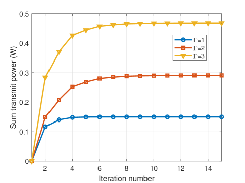
Fig. 3 illustrates the convergence of Algorithm 1 under different SINR requirements. It can be seen that the proposed algorithm converges fast, and six iterations are sufficient to converge, which shows the effectiveness of the proposed algorithm in terms of convergence performance.
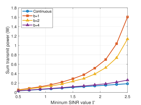
The sum transmit power versus the minimum SINR requirement for continuous and discrete phase shift schemes is shown in Fig. 4. In this figure, denotes the number of bits used to indicate the number of phase shift levels where . For simplicity, we assume that such discrete phase-shift values are obtained by uniformly quantizing the interval . Thus, the set of discrete phase-shift values at each element is given by
| (50) |
Denote as the obtained result of considering continuous phase shifts. We use the rounding method to obtain discrete phase shifts solution , where
| (51) |
With the discrete phase shifts solution , the power control can be obtained by using the iterative power control scheme (25). According to Fig. 4, it is observed that the performance loss due to the rounding is small for large and small minimum SINR value , which indicates that the proposed approach is also suitable to discrete phase shifter with large number of phase shift levels.
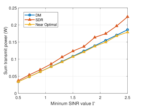
The sum transmit power versus the minimum SINR requirement for DM, SDR, and near optimal solution is given in Fig. 5. In this figure, the near optimal solution is obtained by the algorithm with two steps. In the first step, the nonconvex unit module constraint is added in the objective function by using the penalty method in [33] and then the successive convex approximation method is used to solve the modified optimization problem in the second step. The near optimal solution is calculated by using the successive convex approximation method with multiple initial solutions and the solution with the best objective function is regarded as the near optimal solution. From Fig. 5, it is shown that the DM always achieves the better performance than that of SDR. The reason is that the SDR scheme requires the randomizations to construct a rank-one solution, which can lead to the performance degradation. It can be also seen that DM achieves similar performance with the near optimal solution, which verifies the theoretical findings in Theorem 1.
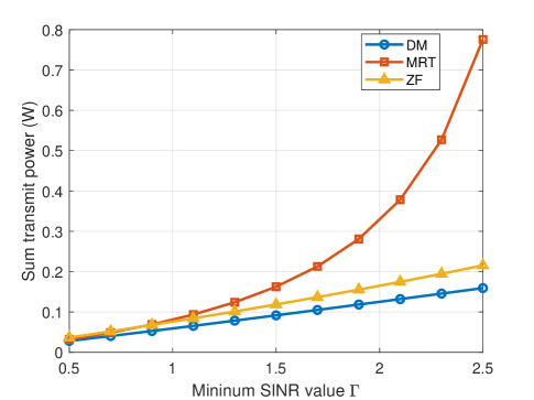
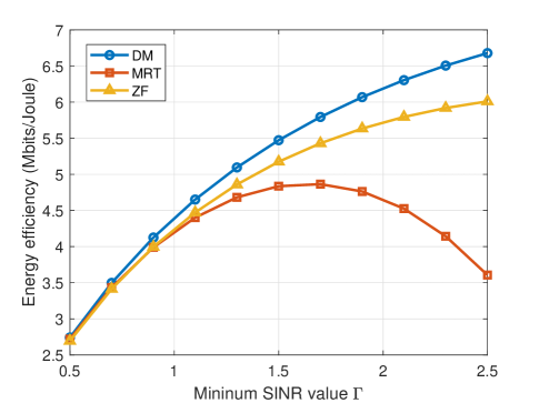
We compare the sum transmit power and energy efficiency performance of DM, MRT, and ZF. Figs. 6 and 7 show the sum transmit power and energy efficiency versus the minimum SINR requirement. In Fig. 7, the energy efficiency is calculated by
| (52) |
where with being the power amplifier efficiency of the BS, is the sum transmit power of the BS, dBm is the circuit power consumption of the BS, dBm is the circuit power consumption of user , dBm is the power consumption of each reflecting element in the RIS, and MHz is the bandwidth of the BS. From these two figures, DM achieves the best performance. In particular, DM can reduce up to 94% and 23% sum transmit power compared to MRT and ZF, respectively. Besides, DM can increase up to 61% and 27% energy efficiency compared to MRT and ZF, respectively. According to Fig. 6, the sum transmit power increases slightly with the minimum SINR requirement for DM and ZF, while it increases rapidly with the minimum SINR requirement for MRT. This is due to the fact that MRT only maximizes the received signal strength without considering the multiuser interference, which indicates that MRT is not suitable for high SINR requirement. It is also found that the energy efficiency of DM and ZF increases with the minimum SINR requirement from Fig. 7. From both Figs. 6 and 7, it is observed that MRT is superior over ZF for low SINR requirement, while ZF is better than MRT for high SINR requirement.
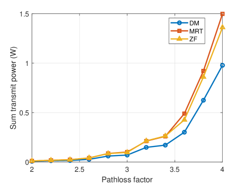
Fig. 8 shows how the sum transmit power changes as the pathloss factor varies. We can see that the sum transmit power of all schemes increases with the pathloss factor. This is because the large pathloss factor results in poor channel gains for the users. It is found that DM achieves the best performance among all schemes. From Fig. 8, DM can achieve the best sum transmit power performance especially for the case that the pathloss factor is high.
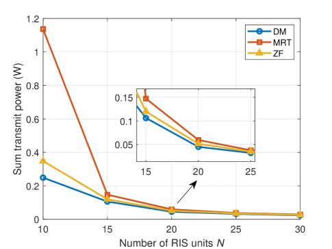
Fig. 9 shows the sum transmit power versus the number of RIS units . From this figure, we can see that the sum transmit power of all schemes monotonically decreases with the number of RIS units. This is because large number of RIS units can lead to high spectral efficiency, which can reduce the transmit power of the system. According to Fig. 9, it can be shown that the decrease speed of sum transmit power for MRT is faster than that for ZF and DM, which indicates that MRT is suitable for the case with large number of RIS units.
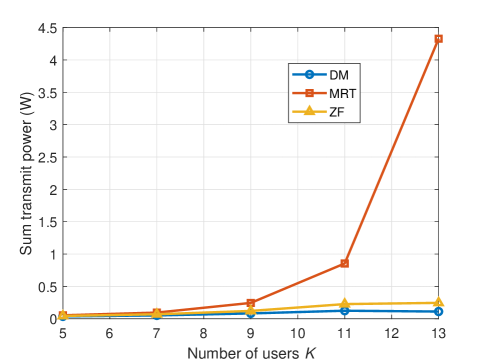
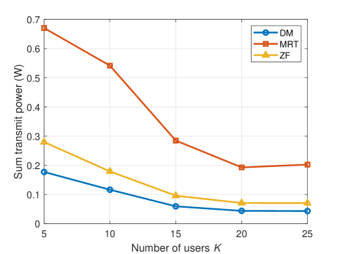
Figs. 10 and 11 depict the sum transmit power versus number of users with and , respectively. From both figures, DM achieves the best performance. In Fig. 10, the sum transmit power increases with the number of users. This is because the multiuser interference is serious for large number of users. It can also be shown that the increase speed of DM is slower than that for MRT or ZF, which shows that DM can save more power than MRT or ZF. Clearly, the DM is always better than MRT and ZF especially when the number of users is large. According to Fig. 11, the sum transmit power tends to decrease with the number of users, which shows the different trends compared to Fig. 10. The reason is that the number of RIS units is fixed in Fig. 10, while the number of RIS units also increases linearly with the number of users in Fig. 11. When the ratio between the number of users and the number of RIS units is fixed, the sum transmit power first decreases with the number of users and then remains stable for high number of users.
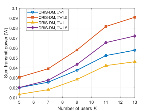
In Fig. 12, we show the sum transmit power versus the number of users for distributed deployment of RIS units. In this figure, the centralized deployment of all RIS units is labeled “CRIS”, while the distributed deployment of RIS units is labeled “DRIS”. In DRIS, we consider the case that there are RISs and the location of RIS is given by m. For each RIS, it is equipped with RIS units. It is found that DRIS achieves the better performance than CRIS, which indicates the benefit of distributed deployment of RISs. Multiple RISs are spatially distributed in DRIS, which can decrease the transmit power between the transceivers.
V Conclusions
In this paper, we have investigated the resource allocation problem for a wireless communication network with an RIS-assisted wireless transmitter. The RIS phase shifts and BS transmit power were jointly optimized to minimize the sum transmit power while satisfying minimum SINR requirements and unit-modulus constraints. To solve this problem, we have proposed the dual method, compared to the SDR, MRT, and ZF beamforming techniques. Moreover, we have analyzed the asymptotic performance of the RIS-assisted communication system with infinitely number of RIS units. Numerical results have shown that the dual method outperforms MRT and ZF schemes in terms of sum transmit power and energy efficiency, especially for high SINR requirements. Furthermore, the distributed deployment of RIS units was shown to be favorable for decreasing the sum transmit power. The optimization of RIS elements allocation is left for our future work.
References
- [1] W. Saad, M. Bennis, and M. Chen, “A vision of 6g wireless systems: Applications, trends, technologies, and open research problems,” IEEE Netw., vol. 34, no. 3, pp. 134–142, 2020.
- [2] W. Yu and T. Lan, “Transmitter optimization for the multi-antenna downlink with per-antenna power constraints,” IEEE Trans. Signal Process., vol. 55, no. 6, pp. 2646–2660, Jun. 2007.
- [3] H. Q. Ngo, E. G. Larsson, and T. L. Marzetta, “Energy and spectral efficiency of very large multiuser MIMO systems,” IEEE Trans. Commun., vol. 61, no. 4, pp. 1436–1449, Apr. 2013.
- [4] S. Buzzi, I. Chih-Lin, T. E. Klein, H. V. Poor, C. Yang, and A. Zappone, “A survey of energy-efficient techniques for 5G networks and challenges ahead,” IEEE J. Sel. Areas Commun., vol. 34, no. 4, pp. 697–709, Apr. 2016.
- [5] S. Zhang, S. Xu, G. Y. Li, and E. Ayanoglu, “First 20 years of green radios,” IEEE Trans. Green Commun. and Netw., vol. 4, no. 1, pp. 1–15, 2020.
- [6] W. Xu, Y. Cui, H. Zhang, G. Y. Li, and X. You, “Robust beamforming with partial channel state information for energy efficient networks,” IEEE J. Sel. Areas Commun., vol. 33, no. 12, pp. 2920–2935, Dec. 2015.
- [7] C. Huang, Z. Yang, G. C. Alexandropoulos, K. Xiong, L. Wei, C. Chen, and Z. Zhang, “Hybrid beamforming for ris-empowered multi-hop terahertz communications: A DRL-based method,” Avilable [oneline]: https://arxiv.org/abs/2009.09380, 2020.
- [8] C. Pan, H. Ren, K. Wang, W. Xu, M. Elkashlan, A. Nallanathan, and L. Hanzo, “Multicell mimo communications relying on intelligent reflecting surfaces,” IEEE Trans. Wireless Commun., vol. 19, no. 8, pp. 5218–5233, 2020.
- [9] C. Pan, H. Ren, K. Wang, M. Elkashlan, A. Nallanathan, J. Wang, and L. Hanzo, “Intelligent reflecting surface enhanced MIMO broadcasting for simultaneous wireless information and power transfer,” Avilable [oneline]: https://arxiv.org/abs/1908.04863, 2019.
- [10] Y. Liu, X. Liu, X. Mu, T. Hou, J. Xu, Z. Qin, M. Di Renzo, and N. Al-Dhahir, “Reconfigurable intelligent surfaces: Principles and opportunities,” Avilable [oneline]: https://arxiv.org/abs/2007.03435, 2020.
- [11] C. Huang, R. Mo, and C. Yuen, “Reconfigurable intelligent surface assisted multiuser MISO systems exploiting deep reinforcement learning,” IEEE J. Sel. Areas Commun., vol. 38, no. 8, pp. 1839–1850, Aug. 2020.
- [12] C. Huang, S. Hu, G. C. Alexandropoulos, A. Zappone, C. Yuen, R. Zhang, M. Di Renzo, and M. Debbah, “Holographic MIMO surfaces for 6G wireless networks: Opportunities, challenges, and trends,” IEEE Wireless Commun., early access, doi: 10.1109/MWC.001.1900534, 2020.
- [13] Z. Yang, M. Chen, W. Saad, W. Xu, M. Shikh-Bahaei, H. V. Poor, and S. Cui, “Energy-efficient wireless communications with distributed reconfigurable intelligent surfaces,” Avilable [oneline]: https://arxiv.org/abs/2005.00269.
- [14] M. Di Renzo, A. Zappone, M. Debbah, M.-S. Alouini, C. Yuen, J. de Rosny, and S. Tretyakov, “Smart radio environments empowered by reconfigurable intelligent surfaces: How it works, state of research, and road ahead,” Avilable [oneline]: https://arxiv.org/abs/2004.09352, 2020.
- [15] Z. Yang, J. Shi, Z. Li, M. Chen, W. Xu, and M. Shikh-Bahaei, “Energy efficient rate splitting multiple access (RSMA) with reconfigurable intelligent surface,” in Proc. IEEE Int. Conf. Commun. Workshop, pp. 1–6, to appear, 2020.
- [16] H. Long, M. Chen, Z. Yang, B. Wang, Z. Li, X. Yun, and M. Shikh-Bahaei, “Reflections in the sky: Joint trajectory and passive beamforming design for secure uav networks with reconfigurable intelligent surface,” Avilable [oneline]: https://arxiv.org/abs/2005.10559, 2020.
- [17] S. Zhou, W. Xu, K. Wang, M. Di Renzo, and M.-S. Alouini, “Spectral and energy efficiency of IRS-assisted MISO communication with hardware impairments,” IEEE Wireless Commun. Lett., 2020.
- [18] X. Hu, C. Zhong, Y. Zhu, X. Chen, and Z. Zhang, “Programmable metasurface based multicast systems: Design and analysis,” Avilable [oneline]: https://arxiv.org/abs/2002.08611, 2020.
- [19] Y. Zhang, C. Zhong, Z. Zhang, and W. Lu, “Sum rate optimization for two way communications with intelligent reflecting surface,” IEEE Commun. Lett., vol. 24, no. 5, pp. 1090–1094, 2020.
- [20] S. V. Hum and J. Perruisseau-Carrier, “Reconfigurable reflectarrays and array lenses for dynamic antenna beam control: A review,” IEEE Trans. Antennas Prop., vol. 62, no. 1, pp. 183–198, Jan. 2013.
- [21] J. Huang, Q. Li, Q. Zhang, G. Zhang, and J. Qin, “Relay beamforming for amplify-and-forward multi-antenna relay networks with energy harvesting constraint,” IEEE Signal Process. Lett., vol. 21, no. 4, pp. 454–458, Apr. 2014.
- [22] K. Ntontin, M. Di Renzo, J. Song, F. Lazarakis, J. de Rosny, D.-T. Phan-Huy, O. Simeone, R. Zhang, M. Debbah, G. Lerosey, M. Fink, S. Tretyakov, and S. Shamai, “Reconfigurable intelligent surfaces vs. relaying: Differences, similarities, and performance comparison,” Avilable [oneline]: https://arxiv.org/abs/1908.08747, 2019.
- [23] M. Jung, W. Saad, M. Debbah, and C. S. Hong, “On the optimality of reconfigurable intelligent surfaces (RISs): Passive beamforming, modulation, and resource allocation,” Avilable [oneline]: https://arxiv.org/abs/1910.00968, 2019.
- [24] X. Yu, D. Xu, D. W. K. Ng, and R. Schober, “Power-efficient resource allocation for multiuser miso systems via intelligent reflecting surfaces,” Avilable [oneline]: https://arxiv.org/abs/2005.06703, 2020.
- [25] D. Xu, X. Yu, Y. Sun, D. W. K. Ng, and R. Schober, “Resource allocation for IRS-assisted full-duplex cognitive radio systems,” Avilable [oneline]: https://arxiv.org/abs/2003.07467, 2020.
- [26] X. Yu, D. Xu, and R. Schober, “MISO wireless communication systems via intelligent reflecting surfaces: (invited paper),” in 2019 IEEE/CIC Int. Conf. Communi. China, Changchun, China, pp. 735–740, 2019.
- [27] M. Hua, Q. Wu, D. W. K. Ng, J. Zhao, and L. Yang, “Intelligent reflecting surface-aided joint processing coordinated multipoint transmission,” Avilable [oneline]: https://arxiv.org/abs/2003.13909, 2020.
- [28] C. Huang, A. Zappone, M. Debbah, and C. Yuen, “Achievable rate maximization by passive intelligent mirrors,” in Proc. IEEE Int. Conf. Acoust., Speech and Signal Process., Calgary, Canada, April. 2018, pp. 3714–3718.
- [29] M. Jung, W. Saad, Y. Jang, G. Kong, and S. Choi, “Performance analysis of large intelligence surfaces (LISs): Asymptotic data rate and channel hardening effects,” IEEE Trans. Wireless Commun., vol. 19, no. 3, pp. 2052–2065, 2020.
- [30] M.-M. Zhao, Q. Wu, M.-J. Zhao, and R. Zhang, “Intelligent reflecting surface enhanced wireless network: Two-timescale beamforming optimization,” Avilable [oneline]: https://arxiv.org/abs/1912.01818, 2019.
- [31] H. Shen, W. Xu, S. Gong, Z. He, and C. Zhao, “Secrecy rate maximization for intelligent reflecting surface assisted multi-antenna communications,” IEEE Commun. Lett., vol. 23, no. 9, pp. 1488–1492, Sep. 2019.
- [32] X. Yu, D. Xu, Y. Sun, D. W. K. Ng, and R. Schober, “Robust and secure wireless communications via intelligent reflecting surfaces,” Avilable [oneline]: https://arxiv.org/abs/1912.01497, 2019.
- [33] Q. Wu and R. Zhang, “Joint active and passive beamforming optimization for intelligent reflecting surface assisted SWIPT under QoS constraints,” IEEE J. Sel. Areas Commun., pp. 1–1, 2020.
- [34] D. Xu, X. Yu, Y. Sun, D. W. K. Ng, and R. Schober, “Resource allocation for secure IRS-assisted multiuser MISO systems,” in Proc. IEEE Globecom Workshops (GC Wkshps), Waikoloa, HI, USA, pp. 1–6, Dec., 2019.
- [35] J. Liu, K. Xiong, Y. Lu, D. W. K. Ng, Z. Zhong, and Z. Han, “Energy efficiency in secure IRS-aided SWIPT,” IEEE Wireless Commun. Lett., pp. 1–1, 2020.
- [36] X. Guan, Q. Wu, and R. Zhang, “Joint power control and passive beamforming in IRS-assisted spectrum sharing,” IEEE Commun. Lett., Jul. 2020.
- [37] C. Huang, A. Zappone, G. C. Alexandropoulos, M. Debbah, and C. Yuen, “Reconfigurable intelligent surfaces for energy efficiency in wireless communication,” IEEE Trans. Wireless Commun., vol. 18, no. 8, pp. 4157–4170, Aug. 2019.
- [38] J. Zhao et al., “Programmable time-domain digital-coding metasurface for non-linear harmonic manipulation and new wireless communication systems,” National Sci. Rev., vol. 6, no. 2, pp. 231–238, 2018.
- [39] J. Y. Dai, W. K. Tang, J. Zhao, X. Li, Q. Cheng, J. C. Ke, M. Z. Chen, S. Jin, and T. J. Cui, “Wireless communications through a simplified architecture based on time-domain digital coding metasurface,” Adv. Mater. Technol., p. 1900044, 2019.
- [40] W. Tang, J. Y. Dai, M. Chen, X. Li, Q. Cheng, S. Jin, K.-K. Wong, and T. J. Cui, “Programmable metasurface-based RF chain-free 8PSK wireless transmitter,” Electron. Lett., vol. 55, no. 7, pp. 417–420, 2019.
- [41] E. Basar, “Transmission through large intelligent surfaces: A new frontier in wireless communications,” in Proc. EuCNC, pp. 112–117, 2019.
- [42] E. Basar, M. Di Renzo, J. De Rosny, M. Debbah, M. Alouini, and R. Zhang, “Wireless communications through reconfigurable intelligent surfaces,” IEEE Access, vol. 7, pp. 116 753–116 773, 2019.
- [43] W. Tang, J. Y. Dai, M. Z. Chen, K. K. Wong, X. Li, X. Zhao, S. Jin, Q. Cheng, and T. J. Cui, “Mimo transmission through reconfigurable intelligent surface: System design, analysis, and implementation,” IEEE J. Sel. Areas Commun., early access, doi: 10.1109/JSAC.2020.3007055, 2020.
- [44] Q. Wu and R. Zhang, “Intelligent reflecting surface enhanced wireless network via joint active and passive beamforming,” IEEE Trans. Wireless Commun., vol. 18, no. 11, pp. 5394–5409, Nov. 2019.
- [45] A. Taha, M. Alrabeiah, and A. Alkhateeb, “Enabling large intelligent surfaces with compressive sensing and deep learning,” Avilable [oneline]: https://arxiv.org/abs/1904.10136, 2019.
- [46] C. Huang, G. C. Alexandropoulos, C. Yuen, and M. Debbah, “Indoor signal focusing with deep learning designed reconfigurable intelligent surfaces,” in Proc. IEEE 20th International Workshop on Signal Processing Advances in Wireless Communications (SPAWC), pp. 1–5, 2019.
- [47] L. Wei, C. Huang, G. C. Alexandropoulos, C. Yuen, Z. Zhang, and M. Debbah, “Channel estimation for RIS-empowered multi-user MISO wireless communications,” Available online: https://arxiv.org/abs/2008.01459, 2020.
- [48] W. Yu and R. Lui, “Dual methods for nonconvex spectrum optimization of multicarrier systems,” IEEE Trans. Commun., vol. 54, no. 7, pp. 1310–1322, July 2006.
- [49] S. Boyd and L. Vandenberghe, Convex optimization. Cambridge University Press, 2004.
- [50] M. Grant, S. Boyd, and Y. Ye, “CVX: Matlab software for disciplined convex programming,” 2008.
- [51] Z. Yang, M. Chen, W. Saad, C. S. Hong, and M. Shikh-Bahaei, “Energy efficient federated learning over wireless communication networks,” Avilable [oneline]: https://arxiv.org/abs/1911.02417, 2019.
- [52] R. D. Yates, “A framework for uplink power control in cellular radio systems,” IEEE J. Sel. Areas Commun., vol. 13, no. 7, pp. 1341–1347, Sep. 1995.
- [53] Q. Wu and R. Zhang, “Intelligent reflecting surface enhanced wireless network: Joint active and passive beamforming design,” in Proc. IEEE Global Commun. Conf., Abu Dhabi, United Arab Emirates, pp. 1–6, Dec. 2018.
- [54] A. M.-C. So, J. Zhang, and Y. Ye, “On approximating complex quadratic optimization problems via semidefinite programming relaxations,” Mathematical Programming, vol. 110, no. 1, pp. 93–110, Jun. 2007.
- [55] S. Huang, H. Yin, J. Wu, and V. C. M. Leung, “User selection for multiuser MIMO downlink with zero-forcing beamforming,” IEEE Trans. Veh. Technol., vol. 62, no. 7, pp. 3084–3097, Sep. 2013.
- [56] M. S. Lobo, L. Vandenberghe, S. Boyd, and H. Lebret, “Applications of second-order cone programming,” Linear algebra and its applications, vol. 284, no. 1-3, pp. 193–228, 1998.
- [57] Y. Mao, B. Clerckx, and V. O. K. Li, “Rate-splitting for multi-antenna non-orthogonal unicast and multicast transmission: Spectral and energy efficiency analysis,” IEEE Trans. Commun., vol. 67, no. 12, pp. 8754–8770, Sept. 2019.
- [58] M. Chen, Z. Yang, W. Saad, C. Yin, H. V. Poor, and S. Cui, “A joint learning and communications framework for federated learning over wireless networks,” to appear, IEEE Trans. Wireless Commun., Avilable [oneline]: https://arxiv.org/abs/1909.07972, 2020.