Fractional antiferromagnetic skyrmion lattice induced by anisotropic couplings
Abstract
Magnetic skyrmions are topological solitons with a nanoscale winding spin texture that hold promise for spintronics applications 1, 2, 3, 4. Until now, skyrmions have been observed in a variety of magnets that exhibit nearly parallel alignment for the neighbouring spins, but theoretically, skyrmions with anti-parallel neighbouring spins are also possible. The latter, antiferromagnetic skyrmions, may allow more flexible control compared to the conventional ferromagnetic skyrmions 5, 6, 7, 8, 9, 10. Here, by combining neutron scattering and Monte Carlo simulations, we show that a fractional antiferromagnetic skyrmion lattice with an incipient meron character 11, 12 is stabilized in MnSc2S4 through anisotropic couplings. Our work demonstrates that the theoretically proposed antiferromagnetic skyrmions can be stabilized in real materials and represents an important step towards implementing the antiferromagnetic-skyrmion based spintronic devices.
pacs:
The concept of topology has revolutionized condensed matter physics: it reveals that the classification of different phases can extend beyond the Landau-Ginzburg-Wilson paradigm of classification by symmetry, bringing about a variety of new phases with topological characters 13. Among the topological entities, magnetic skyrmions with a winding spin texture in real space have triggered enormous interest due to their potential for spintronics applications 1, 2, 3, 4. Information encoded in the nanoscale spin winding of the skyrmions is topologically protected against perturbations, and can be conveniently manipulated with electronic currents 14, 15, 16.
Similar to the vortices that emerge in the Berezinskii-Kosterlitz-Thouless transition, magnetic skymions are conventionally treated as topological solitons in non-linear field theory 17, which implies a continuous ferromagnetic spin alignment at short length scales. This short-range ferromagnetism is indeed a common feature for most of the known skyrmion hosts, including the chiral magnets with antisymmetric Dzyaloshinskii-Moriya interactions (DMI) 3, and the recently discovered centrosymmetric compounds with multiple-spin couplings 18, 19, 20.
However, explorations on skyrmions should not be confined to ferromagnets 21. Theoretical calculations have suggested that skyrmions might be also stabilized in antiferromagnets with two 6, 7 or three 8, 9, 10 sublattices, leading to antiferromagnetic skyrmions (AF-Sks) with anti-parallel nearest-neighbouring (NN) spin alignment, which might complement the skyrmion control in spintronic devices 5. On the other hand, antiferromagnets are often accompanied by strong frustration, which is a known ingredient to enhance fluctuations 22. Thus the marriage between skyrmion and antiferromagnetism 23, 24 might be the key to realize exotic states like magnetic hopfions 25, 26 or even quantum skyrmions 27.
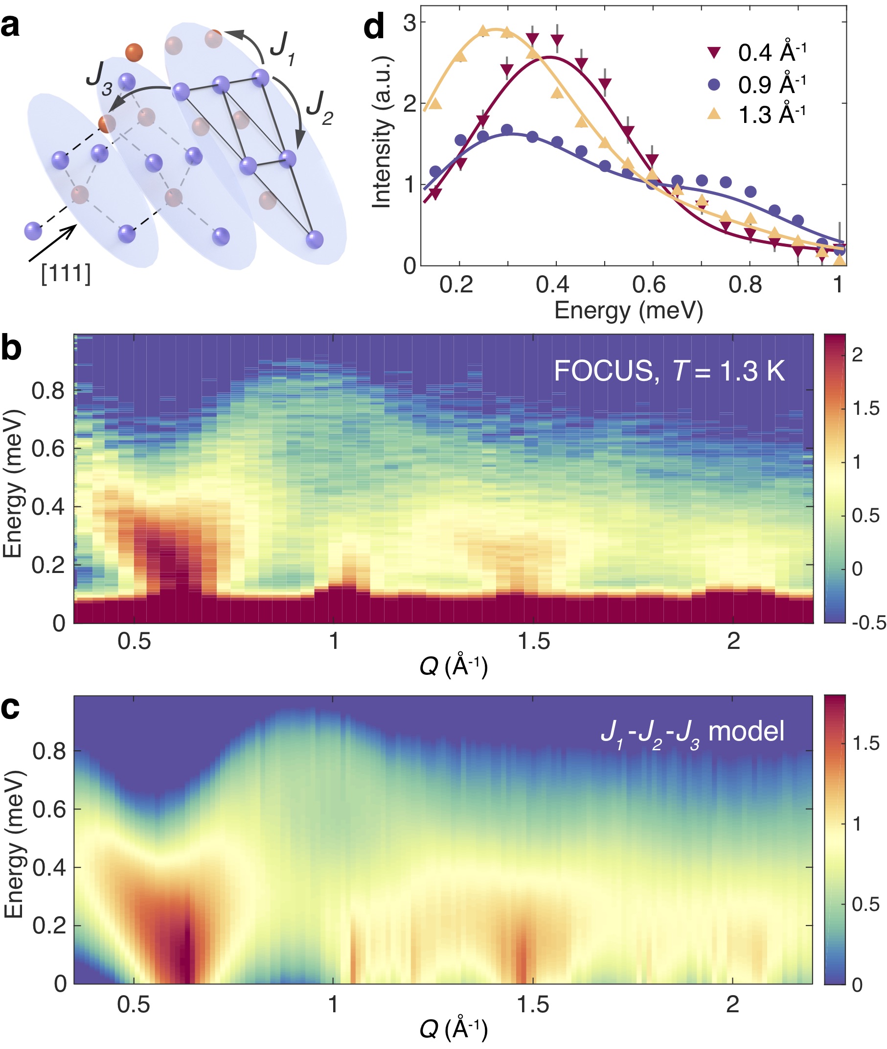
Despite their tantalizing prospects, it is as yet unclear whether AF-Sks can be experi-mentally realized or not. Direct observation of the AF-Sks, e.g. with Lorentz transmission electron microscopy 2, is challenging since the alternating spins cancel the local magnetic field. Although single- magnetic structures can be accurately determined by neutron diffraction, skyrmion lattices are multi- structures and the phase factors between the different propagation vectors are lost. One prominent example is the spinel MnSc2S4 28, 29, where the magnetic Mn2+ ions form a bipartite diamond lattice (see Fig. 1a). A previous neutron diffraction work revealed the existence of a field-induced triple- phase in this antiferromagnet 29, but the exact arrangement of magnetic moments still remains unclear.
In this article, we show that a fractional three-sublattice AF-Sk lattice is realized in the MnSc2S4 triple- phase. By combining state-of-the-art neutron spectroscopy, extensive Monte Carlo simulations, and neutron diffraction, we clarify the microscopic couplings between the Mn2+ spins in MnSc2S4 up to the third-neighbours and, most importantly, establish the existence of a fractional three-sublattice AF-Sk lattice 8, 9, 10 that originates from anisotropic couplings over the nearest-neighbours. The fractionalization of the AF-Sks can be attributed to their close packing 11, leading to incomplete spin wrapping that is reminiscent of the magnetic merons/antimerons 12.
Inelastic neutron scattering (INS) probes the magnon excitations in long-range ordered magnets. Compared to the neutron diffuse scattering that was used to characterize the quasi-elastic spiral spin-liquid correlations in the same compound 29, the rich information that is available in inelastic neutron spectra allows a direct clarification of the further-neighbouring couplings in the spin Hamiltonian, which are crucial in understanding the phase transitions in MnSc2S4 30, 31, 32.
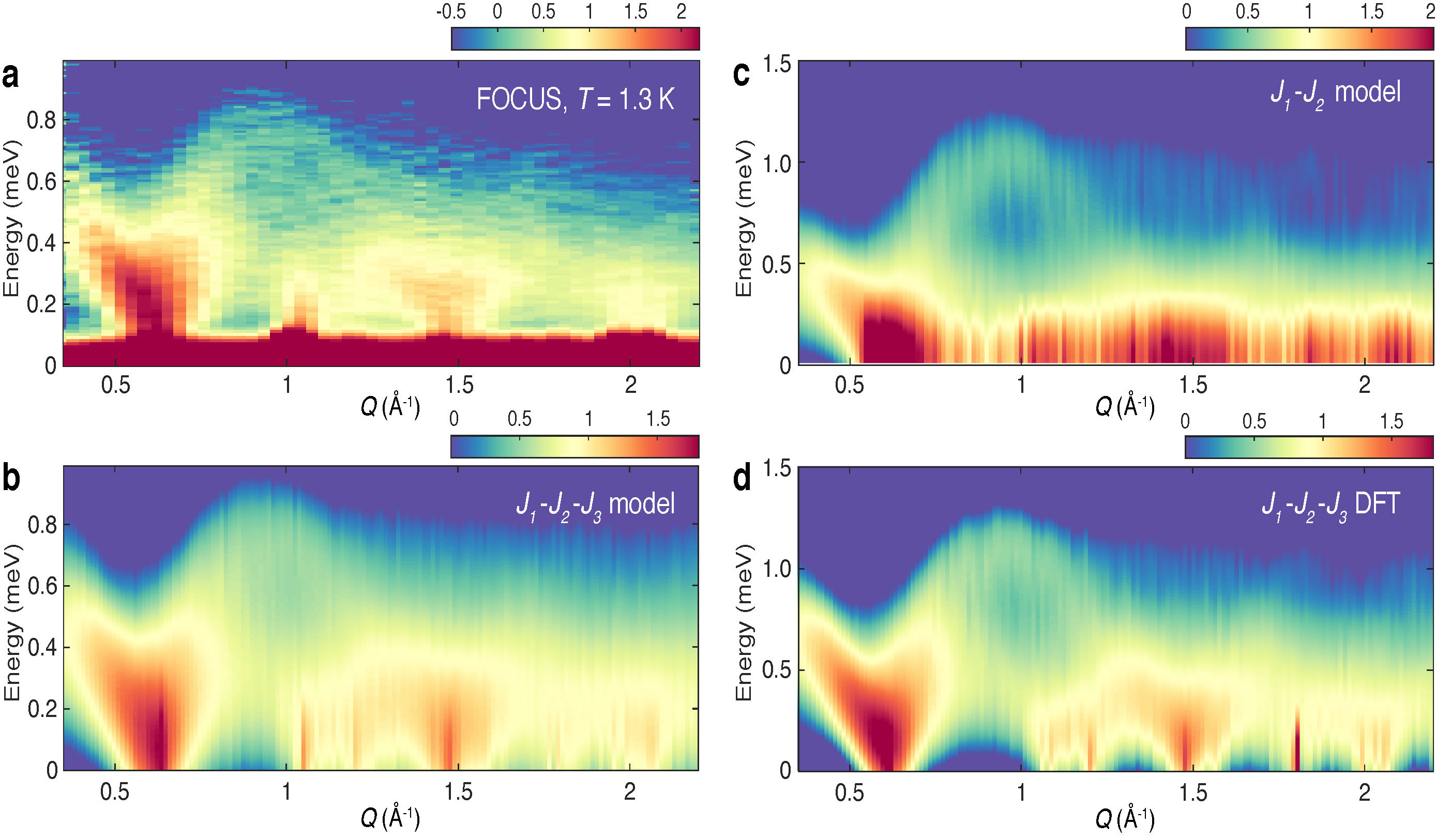
Figure 1b shows our inelastic neutron spectra collected on a powder sample of MnSc2S4 at temperature K in the helical ordered state, which is the parent phase of the field-induced triple- state 29. Strong inelastic scattering intensities are observed, emanating from the magnetic Bragg reflections that belong to the propagation vector = (0.75 0.75 0), and reaching a maximal energy of meV at wavevector Å-1. Compared to other similar spinel compounds 33, 34, 35, the magnon dispersion bandwidth in MnSc2S4 is narrower, consistent with its relatively low ordering temperature of K 28, 29.
Figure 2 presents our INS results collected on a single crystal sample of MnSc2S4 along the high symmetry lines ( 0), ( 0), and ( 0.75 0) in reciprocal space. No excitation gap can be resolved, which is compatible with the absence of single-ion anisotropy up to the second order in spin operators due to the electron configuration of the Mn2+ ions 36. A representative energy scan at (0 0.75 0) shown in Fig. 2a reveals rather broad excitations, suggesting the appearance of multiple magnon bands.
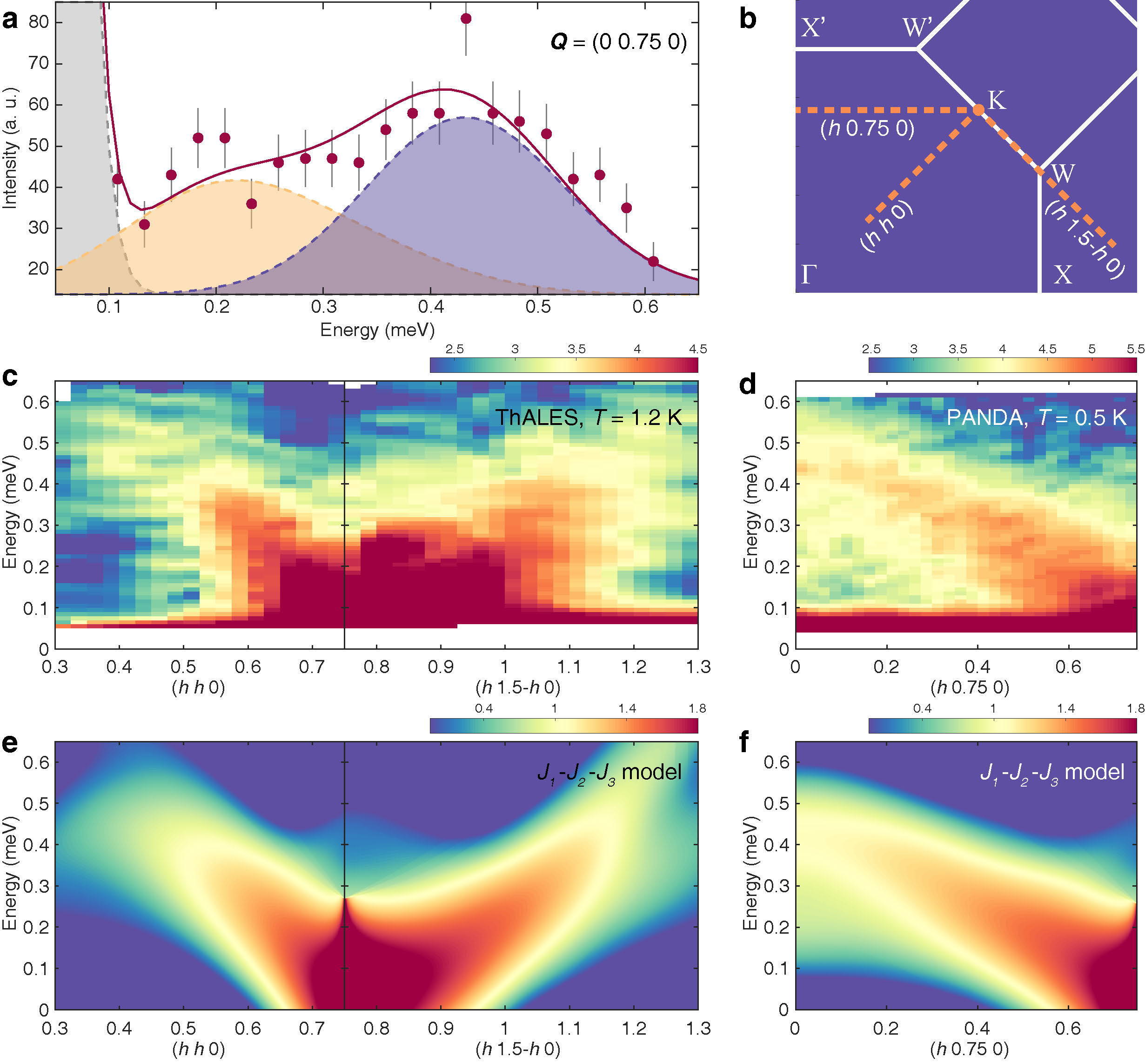
Using linear spin wave theory, we are able to model the spin dynamics with Hamiltonian , where is the exchange coupling between Heisenberg spins and . As explained in Fig. S1 of the Supplementary Information, it is necessary to include couplings up to the third-neighbours 30, 31, 32 in order to reproduce the measured INS spectra. The fitted coupling strengths are K, K, and K at the nearest-, second-, and third-neighbours, respectively. Representative fits to the powder data at selected positions are shown in Fig. 1d. The overall calculated spectra are presented in Fig. 1c and Fig. 2e,f for comparison with the powder and single crystal experimental data, respectively. As shown in Fig. 2a for the energy scan at (0 0.75 0), contributions from different magnetic domains are necessary to describe the broad excitations in the single crystal data.
Although the -- model successfully captures the spin dynamics in the helical phase of MnSc2S4, it fails to account for the field-induced triple- phase 29, which implies the necessity of even weaker perturbations that are beyond the INS resolution. Such a perturbation-dominated scenario is allowed in MnSc2S4 due to its enormous ground state degeneracy 30, 29. Theoretical calculations on centrosymmetric systems have revealed that perturbations from the high-order analogs of the Ruderman-Kittel-Kasuya-Yosida (RKKY) interactions can often stabilize a triple- phase 37, 38. However, this mechanism fails in MnSc2S4 because the insulating character of this compound rules out any RKKY-like interactions that rely on the conduction electrons.
Through extensive Monte Carlo simulations, we explored the effect of different perturbations that are compatible with the symmetries of the lattice 31, and revealed that the triple- phase in MnSc2S4 can be stabilized by anisotropic couplings at the nearest-neighbours together with a fourth-order single-ion anisotropy term that might be microscopically derived from the spin-orbit coupling and dipolar interactions 31. The perturbed -- Hamiltonian now reads
| (1) |
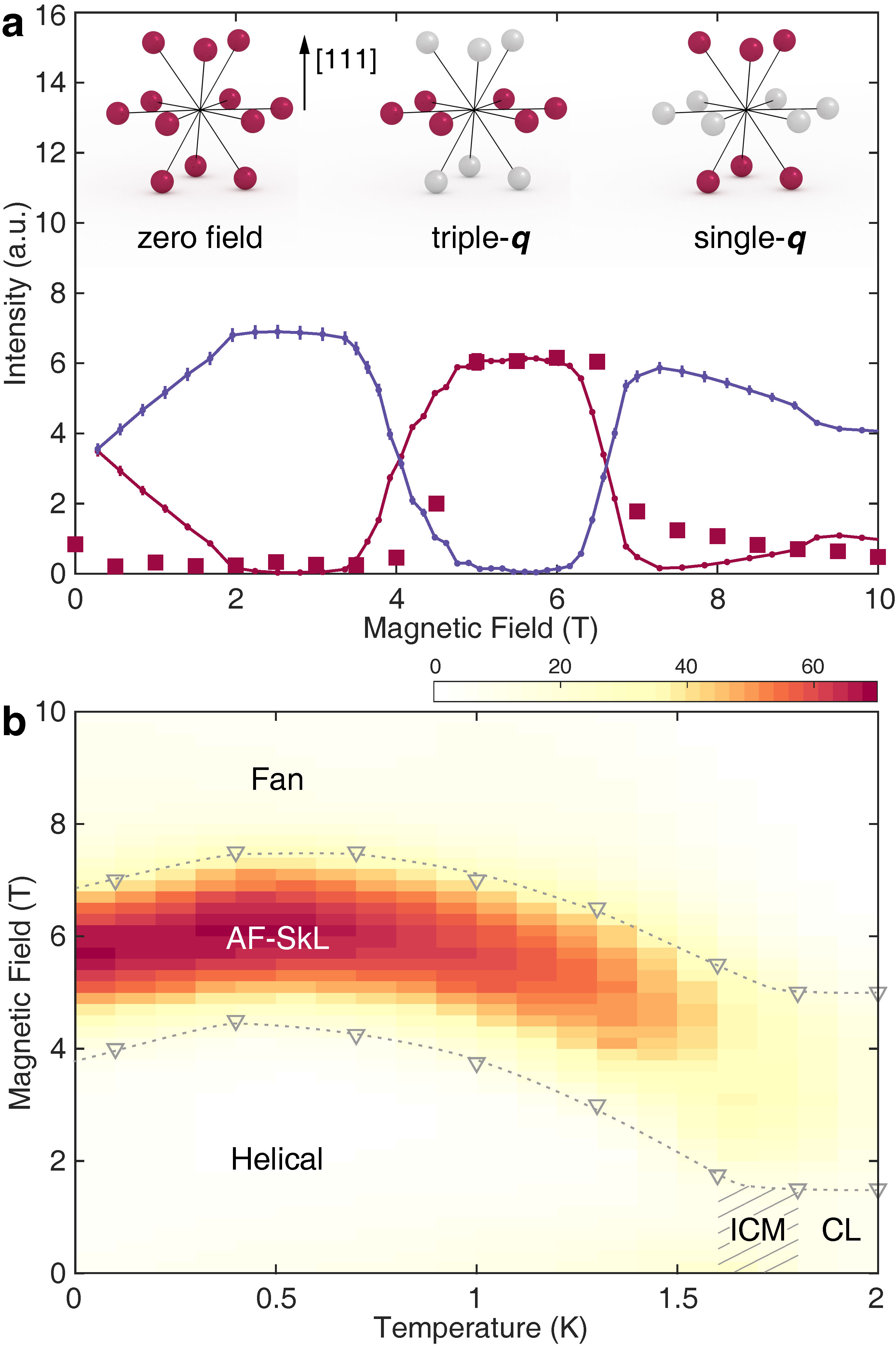
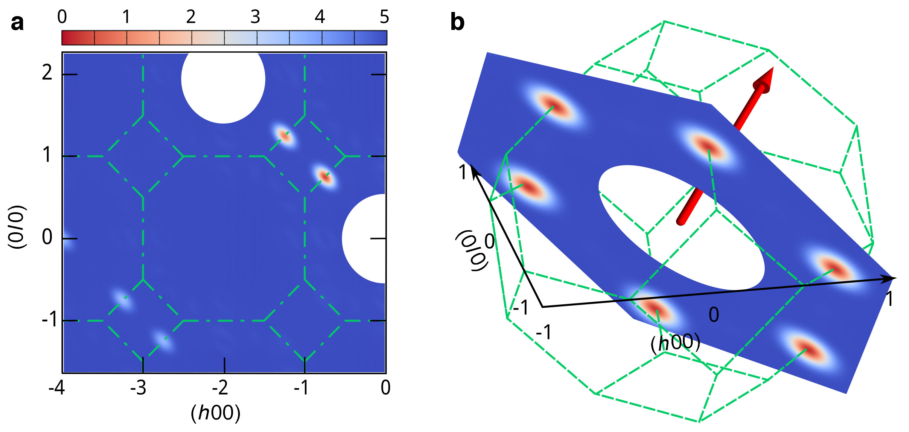
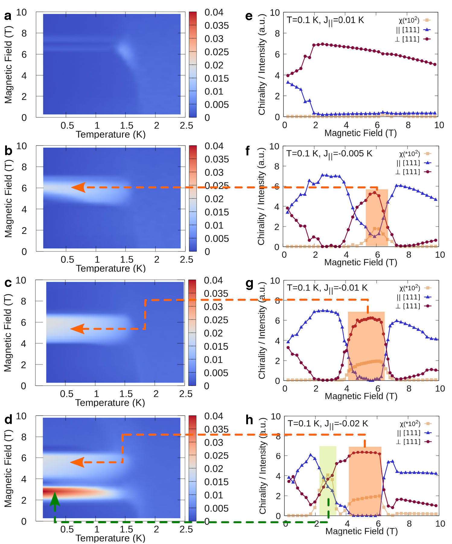
where is the perturbation term due to the NN anisotropic couplings, in which is the anisotropic coupling strength and is the unitary direction vector along the NN bonds; describes a weak fourth-order single-ion anisotropy that is needed to stabilize a zero-field helical ground state 36; is the conventional Zeeman term for spins in a magnetic field along the [111] direction. In our minimal Hamiltonian, the anisotropic is found to be the only term that can induce a triple- phase. Through comparison with the experimental phase diagram presented in Fig. 3, the perturbation parameters can be determined to be K and K. As exemplified in Fig. 3a, only one triple- domain with propagation vectors lying within the (111) plane is stabilized in field 29, and the consequent non-monotonous evolution of the domain distribution is successfully reproduced in our simulations. As shown in Fig. S3 of the Supplementary Information, the magnitude of the total scalar spin chirality increases sharply upon entering the triple- phase, evidencing a magnetic structure that is topologically different from the single- helical phase 23, 8.
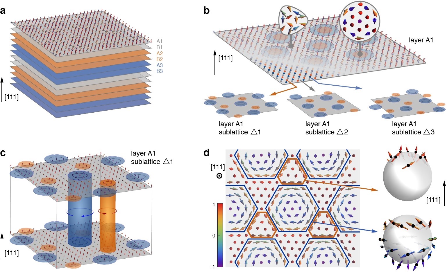
With Monte Carlo simulations, we can directly inspect the triple- structure by layers, in which the Mn2+ ions form a triangular lattice (see Figs. 1a and 4a). As expected for antiferromagnets, the spin configuration in one layer shown in Fig. 4b involve nearly anti-parallel spins at the nearest-neighbours. However, if the whole triangular lattice is separated into three sublattices 10, 8 as shown in the insets of Fig. 4b, a smooth whirling texture will emerge in each sublattice, and the only difference among the sublattices is an overall shift of whorls. As described in Figs. 4c and d, spins at the centers of the whorls are anti-aligned with field, leading to a texture that is similar to the skyrmion lattices 1. Due to the short distance between the centers of the whorls, skyrmions in the triangular sublattices are not wrapping the full sphere, but are fractionalized into two blocks with opposite winding directions 11, forming a pair of incipient meron and antimeron 12 as indicated in Fig. 4d. When the three sublattices are added together as shown schematically in Fig. 4b, fractional skyrmions with opposite magnetizations overlap in the whole triangular lattice, leading to oscillating components near the center of the whorls and -like alignments for the components close to the periphery, where () are magnetic moments along (perpendicular to) the [111] direction. Therefore, each (111) layer in the triple- phase realizes a fractional AF-Sk lattice that is composed of three sublattices 8.
Stacking of AF-Sk lattices along the [111] direction is determined by the propagation vectors and the Mn2+ positions within the (111) layers. In the Methods section, we present an analytical ansatz for spins at general positions constructed as a superposition of three helical modulations, and the correctness of the fractional AF-Sk lattice is verified through comparison against the neutron diffraction dataset shown in Fig. S7 of the Supplementary Information. The bipartite character of the diamond lattice leads to bilayers with exactly the same spin configurations as explained in Fig. 4a, thus realizing three consecutive AF-Sk bilayers with shifted whorl centers. Such a stacking order leads to AF-Sk tubes along the [111] direction shown in Fig. 4c, which is a common feature for many skyrmion lattices 39, 40.
The fractional AF-Sk lattice established in our work demonstrates that even antiferro-magnets can exhibit topologically non-trivial spin textures. In MnSc2S4, the AF-Sk lattice inherits the three-sublattice character of the triangular lattice in the (111) layers. However, the mechanism we discovered, which utilizes anisotropic couplings to stabilize a triple- phase, can be generalized to AF systems with different geometries 41, 42. Especially, on the bipartite honeycomb lattice 43, anisotropic couplings might stabilize a two-sublattice AF-Sk lattice with opposite spin winding textures, thus lending an ideal platform to explore the AF-Sk transport 6, 7.
The spin dynamics of the AF-Sks also deserves further investigations. In chiral systems, the lifetime of isolated AF-Sks is known to be enhanced by the DMI 44. It is therefore interesting to compare the effect of the antisymmetric couplings on the lifetime of the AF-Sks in centrosymmetric systems. For the AF-Sk lattice, magnons propagating through a topological spin texture might carry a Berry phase and thus experience a fictitious magnetic field 45, 46, leading to the thermal Hall effect that can be utilized for magnonics applications. Furthermore, recent calculations on a three-sublattice AF-Sk lattice that is similar to the triple- phase in MnSc2S4 revealed the lowest magnon band to be topological non-trivial 9. The consequent chiral magnon edge states allow magnon transport without backscattering 47 and could further reduce the energy dissipation in magnonics devices.
In summary, our combined neutron scattering and Monte Carlo simulation works clarify the microscopic spin couplings in MnSc2S4 and establish the existence of a fractional AF-Sk lattice that is induced by the anisotropic couplings. Our work shows that topological structures can be stabilized in antiferromagnets, which is an important step in fullfilling spintronic devices that aim to achieve efficient operations with a minimal scale.
I Methods
Inelastic neutron scattering experiments. Inelastic neutron scattering experiments on a powder sample of MnSc2S4 were performed on FOCUS at the Swiss Spallation Neutron Source SINQ of the Paul Scherrer Institut PSI. For the measurements, about 4 g of MnSc2S4 powder sample synthesized through the solid-state reactions 48 was filled into an annular-shaped aluminum can with outer/inner diameters of 12/10 mm. An orange cryostat with an additional roots pump was used, enabling a base temperature of 1.3 K. A setup with 5.0 Å incoming neutron wavelength was employed.
Inelastic neutron scattering experiments on a single crystal sample of MnSc2S4 grown with the chemical transport reaction technique 29 were performed on ThALES 49, 50 at the Institut Laue-Langevin ILL and PANDA 51, 52 at the Heinz Maier-Leibnitz Zentrum MLZ. Five crystals with a total mass of mg were co-aligned with as the horizontal scattering plane. For the experiment on ThALES, a cryomagnet together with an additional roots pump was used, which enabled a base temperature of 1.2 K and a maximal vertical field of 10 T. For better resolution, the Si(111) monochromator and PG(002) analyzer with double focusing were used. A Be-filter between the sample and analyzer and a radial collimator between the analyzer and detector were mounted. The final neutron momentum was fixed at 1.3 Å-1. For the experiment on PANDA, a 3He cryostat was used, which enabled a base temperature of K. PG(002) monochromator and analyzer with double focusing were employed. The final neutron momentum was fixed at 1.3 Å-1. A cooled Be filter was mounted before the sample to remove the higher-order neutrons.
Linear spin wave calculations and fits for the INS spectra were performed using the SpinW package 53. Input data for the fits are the three integrated intensities shown in Fig. 1b. The spin Hamiltonian of the -- model has the helical ground state with a propagation vector (0.75 0.75 0).
Neutron diffraction experiments. Neutron diffraction experiment was performed on the diffractometer D23 at the ILL to map out the phase diagram shown in Fig. 3. Incoming neutron wavelength of 1.27 Å was selected by the Cu(200) monochromator. A dilution refrigerator with a base temperature of 50 mK together with a magnet that supplies a field up to 12 T was employed. The MnSc2S4 crystal was aligned with the (111) direction along the vertical field direction. To map out the phase diagram, we first cooled the crystal in zero field, then perform rocking scan for the (0.75 0) reflection with increasing and decreasing fields.
The neutron diffraction dataset in the triple- phase was collected on TriCS (now ZEBRA) at SINQ, PSI. Incoming neutron wavelength of 2.32 Å was selected by the PG(002) monochromator. A PG filter was mounted before the sample. A cryomagnet together with a roots pump was employed for the measurements. 67 reflections were collected at = 1.60 K in a magnetic field of 3.5 T along the [111] direction.
Monte Carlo simulations. Monte Carlo simulations were performed using the Metropolis algorithm by lowering the temperature in an annealing scheme and computing 500 independent runs initialized by different random numbers for each temperature and external magnetic field. Simulations were performed in magnetic site clusters, with and periodic boundary conditions. In order to compare the classical MC simulations with the experimental results, the factor in the computed thermal averages of relevant quantities was replaced by the quantum mechanical expectation value following Ref. 54.
II Acknowledgements
We acknowledge S. Tóth and S. Ward for help in the analysis of the neutron spectra. We thank A. Scaramucci for the initial trial on the Monte Carlo simulations. We acknowledge helpful discussions with M. Pregelj, S.B. Lee, T.-h. Arima, T. Nakajima, J.S. White, and Y. Su. S.G. acknowledges fruitful discussions at RIKEN CEMS. F.A.G.A. and H.D.R thank R. Borzi for fruitful discussions. H.D.R. thanks M. Zhitomirsky for helpful discussions about the Monte Carlo simulations. Our neutron scattering experiments were performed at the Swiss Spallation Neutron Source SINQ, Paul Scherrer Institut, Villigen, Switzerland, the Heinz Maier-Leibnitz Zentrum MLZ, Garching, Germany, and the Institut Laue-Langevin ILL, Grenoble, France. This work was supported by the Swiss National Science Foundation under Grants No. 20021-140862, No. 20020-152734, the SCOPES project No. IZ73Z0-152734/1, and Centro Latinoamericano-Suizo under the Seed money Grant No. SMG1811. Our work was additionally supported by the Deutsche Forschungsgemeinschaft by the Transregional Collaborative Research Center TRR 80. D.C.C., F.A.G.A., and H.D.R. are partially supported by CONICET (PIP 2015-813), SECyT UNLP PI+D X792 and X788, PPID X039. H.D.R. acknowledges support from PICT 2016-4083.
III Author contributions
O.Z. designed and coordinated the project. V.T. prepared the single crystals. S.G., O.Z., and C.R. performed the inelastic neutron scattering experiments with T.F. as the local contact for FOCUS, P.S. and M.B. for ThALES, P.C. and A.S. for PANDA. S.G. analyzed the neutron spectra with input from O.Z., T.F., and C.R. Neutron diffraction experiments were performed by G.K. and O.Z with E.R. as the local contact. Theoretical analysis and Monte Carlo simulations were performed by H.D.R., F.G.A., and D.C.C. The manuscript was prepared by S.G., H.D.R., and O.Z. with input from all co-authors.
References
- Mühlbauer et al. 2009 S. Mühlbauer, B. Binz, F. Jonietz, C. Pfleiderer, A. Rosch, A. Neubauer, R. Georgii, and P. Böni, Skyrmion lattice in a chiral magnet, Science 323, 915 (2009).
- Yu et al. 2010 X. Z. Yu, Y. Onose, N. Kanazawa, J. H. Park, J. H. Han, Y. Matsui, N. Nagaosa, and Y. Tokura, Real-space observation of a two-dimensional skyrmion crystal, Nature 465, 901 (2010).
- Nagaosa and Tokura 2013 N. Nagaosa and Y. Tokura, Topological properties and dynamics of magnetic skyrmions, Nat. Nano. 8, 899 (2013).
- Fert et al. 2017 A. Fert, N. Reyren, and V. Cros, Magnetic skyrmions: advances in physics and potential applications, Nat. Rev. Mater. 2, 17031 (2017).
- Baltz et al. 2018 V. Baltz, A. Manchon, M. Tsoi, T. Moriyama, T. Ono, and Y. Tserkovnyak, Antiferromagnetic spintronics, Rev. Mod. Phys. 90, 015005 (2018).
- Barker and Tretiakov 2016 J. Barker and O. A. Tretiakov, Static and dynamical properties of antiferromagnetic skyrmions in the presence of applied current and temperature, Phys. Rev. Lett. 116, 147203 (2016).
- Zhang et al. 2016 X. Zhang, Y. Zhou, and M. Ezawa, Antiferromagnetic skyrmion: Stability, creation and manipulation, Sci. Rep. 6, 24795 (2016).
- Rosales et al. 2015 H. D. Rosales, D. C. Cabra, and P. Pujol, Three-sublattice skyrmion crystal in the antiferromagnetic triangular lattice, Phys. Rev. B 92, 214439 (2015).
- Díaz et al. 2019 S. A. Díaz, J. Klinovaja, and D. Loss, Topological magnons and edge states in antiferromagnetic skyrmion crystals, Phys. Rev. Lett. 122, 187203 (2019).
- Kamiya and Batista 2014 Y. Kamiya and C. D. Batista, Magnetic vortex crystals in frustrated mott insulator, Phys. Rev. X 4, 011023 (2014).
- Lin et al. 2015 S.-Z. Lin, A. Saxena, and C. D. Batista, Skyrmion fractionalization and merons in chiral magnets with easy-plane anisotropy, Phys. Rev. B 91, 224407 (2015).
- Yu et al. 2018 X. Z. Yu, W. Koshibae, Y. Tokunaga, K. Shibata, Y. Taguchi, N. Nagaosa, and Y. Tokura, Transformation between meron and skyrmion topological spin textures in a chiral magnet, Nature 564, 95 (2018).
- Wen 2017 X.-G. Wen, Colloquium: Zoo of quantum-topological phases of matter, Rev. Mod. Phys. 89, 041004 (2017).
- Jonietz et al. 2010 F. Jonietz, S. Mühlbauer, C. Pfleiderer, A. Neubauer, W. Münzer, A. Bauer, T. Adams, R. Georgii, P. Böni, R. A. Duine, K. Everschor, M. Garst, and A. Rosch, Spin transfer torques in MnSi at ultralow current densities, Science 330, 1648 (2010).
- Yu et al. 2012 X. Yu, N. Kanazawa, W. Zhang, T. Nagai, T. Hara, K. Kimoto, Y. Matsui, Y. Onose, and Y. Tokura, Skyrmion flow near room temperature in an ultralow current density, Nat. Commun. 3, 988 (2012).
- White et al. 2012 J. S. White, I. Levatić, A. A. Omrani, N. Egetenmeyer, K. Prša, I. Živković, J. L. Gavilano, J. Kohlbrecher, M. Bartkowiak, H. Berger, and H. M. Rønnow, Electric field control of the skyrmion lattice in Cu2OSeO3, J. Phys.: Condens. Matter 24, 432201 (2012).
- Rößzler et al. 2006 U. K. Rößzler, A. N. Bogdanov, and C. Pfleiderer, Spontaneous skyrmion ground states in magnetic metals, Nature 442, 797 (2006).
- Kurumaji et al. 2019 T. Kurumaji, T. Nakajima, M. Hirschberger, A. Kikkawa, Y. Yamasaki, H. Sagayama, H. Nakao, Y. Taguchi, T.-h. Arima, and Y. Tokura, Skyrmion lattice with a giant topological Hall effect in a frustrated triangular-lattice magnet, Science 365, 914 (2019).
- Hirschberger et al. 2019 M. Hirschberger, T. Nakajima, S. Gao, L. Peng, A. Kikkawa, T. Kurumaji, M. Kriener, Y. Yamasaki, H. Sagayama, H. Nakao, K. Ohishi, K. Kakurai, Y. Taguchi, X. Yu, T.-h. Arima, and Y. Tokura, Skyrmion phase and competing magnetic orders on a breathing kagomé lattice, Nat. Commun. 10, 5831 (2019).
- Khanh et al. 2020 N. D. Khanh, T. Nakajima, X. Yu, S. Gao, K. Shibata, M. Hirschberger, Y. Yamasaki, H. Sagayama, H. Nakao, L. Peng, K. Nakajima, R. Takagi, T.-h. Arima, Y. Tokura, and S. Seki, Nanometric square skyrmion lattice in a centrosymmetric tetragonal magnet, Nat. Nanotechnol. 15, 444 (2020).
- Sokolov et al. 2019 D. A. Sokolov, N. Kikugawa, T. Helm, H. Borrmann, U. Burkhardt, R. Cubitt, J. S. White, E. Ressouche, M. Bleuel, K. Kummer, A. P. Mackenzie, and U. K. Rößler, Metamagnetic texture in a polar antiferromagnet, Nat. Phys. 15, 671 (2019).
- Balents 2010 L. Balents, Spin liquids in frustrated magnets, Nature 464, 199 (2010).
- Okubo et al. 2012 T. Okubo, S. Chung, and H. Kawamura, Multiple- states and the skyrmion lattice of the triangular-lattice Heisenberg antiferromagnet under magnetic fields, Phys. Rev. Lett. 108, 017206 (2012).
- Leonov and Mostovoy 2015 A. O. Leonov and M. Mostovoy, Multiply periodic states and isolated skyrmions in an anisotropic frustrated magnet, Nat. Commun. 6 (2015).
- Sutcliffe 2017 P. Sutcliffe, Skyrmion knots in frustrated magnets, Phys. Rev. Lett. 118, 247203 (2017).
- Rybakov et al. 2019 F. N. Rybakov, N. S. Kiselev, A. B. Borisov, L. Döring, C. Melcher, and S. Blügel, Magnetic hopfions in solids, arXiv:1904.00250 (2019).
- Lohani et al. 2019 V. Lohani, C. Hickey, J. Masell, and A. Rosch, Quantum skyrmions in frustrated ferromagnets, arXiv:1901.03343 (2019).
- Fritsch et al. 2004 V. Fritsch, J. Hemberger, N. Büttgen, E. W. Scheidt, H. A. Krug von Nidda, A. Loidl, and V. Tsurkan, Spin and orbital frustration in MnSc2S4 and FeSc2S4, Phys. Rev. Lett. 92, 116401 (2004).
- Gao et al. 2017 S. Gao, O. Zaharko, V. Tsurkan, Y. Su, J. S. White, G. S. Tucker, B. Roessli, F. Bourdarot, R. Sibille, D. Chernyshov, T. Fennell, A. Loidl, and C. Rüegg, Spiral spin-liquid and the emergence of a vortex-like state in MnSc2S4, Nat. Phys. 13, 157 (2017).
- Bergman et al. 2007 D. Bergman, J. Alicea, E. Gull, S. Trebst, and L. Balents, Order-by-disorder and spiral spin-liquid in frustrated diamond-lattice antiferromagnets, Nat. Phys. 3, 487 (2007).
- Lee and Balents 2008 S. Lee and L. Balents, Theory of the ordered phase in A-site antiferromagnetic spinels, Phys. Rev. B 78, 144417 (2008).
- Iqbal et al. 2018 Y. Iqbal, T. Müller, H. O. Jeschke, R. Thomale, and J. Reuther, Stability of the spiral spin liquid in MnSc2S4, Phys. Rev. B 98, 064427 (2018).
- Zaharko et al. 2011 O. Zaharko, N. B. Christensen, A. Cervellino, V. Tsurkan, A. Maljuk, U. Stuhr, C. Niedermayer, F. Yokaichiya, D. N. Argyriou, M. Boehm, and A. Loidl, Spin liquid in a single crystal of the frustrated diamond lattice antiferromagnet CoAl2O4, Phys. Rev. B 84, 094403 (2011).
- MacDougall et al. 2016 G. J. MacDougall, A. A. Aczel, Y. Su, W. Schweika, E. Faulhaber, A. Schneidewind, A. D. Christianson, J. L. Zarestky, H. D. Zhou, D. Mandrus, and S. E. Nagler, Revisiting the ground state of CoAl2O4: Comparison to the conventional antiferromagnet MnAl2O4, Phys. Rev. B 94, 184422 (2016).
- Ge et al. 2017 L. Ge, J. Flynn, J. A. M. Paddison, M. B. Stone, S. Calder, M. A. Subramanian, A. P. Ramirez, and M. Mourigal, Spin order and dynamics in the diamond-lattice Heisenberg antiferromagnets CuRh2O4 and CoRh2O4, Phys. Rev. B 96, 064413 (2017).
- Watanabe 1957 H. Watanabe, On the ground level splitting of Mn++ and Fe+++ in nearly cubic crystalline field, Prog. Theor. Phys. 18, 405 (1957).
- Akagi et al. 2012 Y. Akagi, M. Udagawa, and Y. Motome, Hidden multiple-spin interactions as an origin of spin scalar chiral order in frustrated kondo lattice models, Phys. Rev. Lett. 108, 096401 (2012).
- Hayami et al. 2017 S. Hayami, R. Ozawa, and Y. Motome, Effective bilinear-biquadratic model for noncoplanar ordering in itinerant magnets, Phys. Rev. B 95, 224424 (2017).
- Milde et al. 2013 P. Milde, D. Köhler, J. Seidel, L. M. Eng, A. Bauer, A. Chacon, J. Kindervater, S. Mühlbauer, C. Pfleiderer, S. Buhrandt, C. Schütte, and A. Rosch, Unwinding of a skyrmion lattice by magnetic monopoles, Science 340, 1076 (2013).
- Karube et al. 2016 K. Karube, J. S. White, N. Reynolds, J. L. Gavilano, H. Oike, A. Kikkawa, F. Kagawa, Y. Tokunaga, H. M. Ronnow, Y. Tokura, and Y. Taguchi, Robust metastable skyrmions and their triangular-square lattice structural transition in a high-temperature chiral magnet, Nat. Mater. 15, 1237 (2016).
- Attig and Trebst 2017 J. Attig and S. Trebst, Classical spin spirals in frustrated magnets from free-fermion band topology, Phys. Rev. B 96, 085145 (2017).
- Balla et al. 2019 P. Balla, Y. Iqbal, and K. Penc, Affine lattice construction of spiral surfaces in frustrated Heisenberg models, Phys. Rev. B 100, 140402 (2019).
- Göbel et al. 2017 B. Göbel, A. Mook, J. Henk, and I. Mertig, Antiferromagnetic skyrmion crystals: Generation, topological Hall, and topological spin Hall effect, Phys. Rev. B 96, 060406 (2017).
- Bessarab et al. 2019 P. F. Bessarab, D. Yudin, D. R. Gulevich, P. Wadley, M. Titov, and O. A. Tretiakov, Stability and lifetime of antiferromagnetic skyrmions, Phys. Rev. B 99, 140411 (2019).
- van Hoogdalem et al. 2013 K. A. van Hoogdalem, Y. Tserkovnyak, and D. Loss, Magnetic texture-induced thermal Hall effects, Phys. Rev. B 87, 024402 (2013).
- Daniels et al. 2019 M. W. Daniels, W. Yu, R. Cheng, J. Xiao, and D. Xiao, Topological spin Hall effects and tunable skyrmion Hall effects in uniaxial antiferromagnetic insulators, Phys. Rev. B 99, 224433 (2019).
- Roldán-Molina et al. 2016 A. Roldán-Molina, A. S. Nunez, and J. Fernández-Rossier, Topological spin waves in the atomic-scale magnetic skyrmion crystal, New J. Phys. 18, 045015 (2016).
- Krimmel et al. 2006 A. Krimmel, M. Mücksch, V. Tsurkan, M. M. Koza, H. Mutka, C. Ritter, D. V. Sheptyakov, S. Horn, and A. Loidl, Magnetic ordering and spin excitations in the frustrated magnet MnSc2S4, Phys. Rev. B 73, 014413 (2006).
- Boehm et al. 2015 M. Boehm, P. Steffens, J. Kulda, M. Klicpera, S. Roux, P. Courtois, P. Svoboda, J. Saroun, and V. Sechovsky, ThALES—three axis low energy spectroscopy for highly correlated electron systems, Neutron News 26, 18 (2015).
- Zaharko et al. 2016 O. Zaharko, M. Boehm, T. Fennell, S. Gao, C. Rüegg, P. Steffens, and V. Tsurkan, Spin dynamics in the order-by-disorder candidate MnSc2S4, Institut Laue-Langevin (ILL) 10.5291/ILL-DATA.4-01-1500 (2016).
- Schneidewind and Čermák 2015 A. Schneidewind and P. Čermák, Heinz Maier-Leibnitz Zentrum et al. PANDA: Cold three axes spectrometer, J. Large-scale Research Facilities 1, A12 (2015).
- Utschick et al. 2016 C. Utschick, M. Skoulatos, A. Schneidewind, and P. Böni, Optimizing the triple-axis spectrometer PANDA at the MLZ for small samples and complex sample environment conditions, Nucl. Instr. Meth. in Phys. Res. Sect. A 837, 88 (2016).
- Toth and Lake 2015 S. Toth and B. Lake, Linear spin wave theory for single-Q incommensurate magnetic structures, J. Phys.: Condens. Matter 27, 166002 (2015).
- Johnston et al. 2011 D. C. Johnston, R. J. McQueeney, B. Lake, A. Honecker, M. E. Zhitomirsky, R. Nath, Y. Furukawa, V. P. Antropov, and Y. Singh, Magnetic exchange interactions in BaMn2As2: A case study of the -- Heisenberg model, Phys. Rev. B 84, 094445 (2011).
Fractional antiferromagnetic skyrmion lattice induced by anisotropic couplings
Supplementary Information
Comparison for different spin models
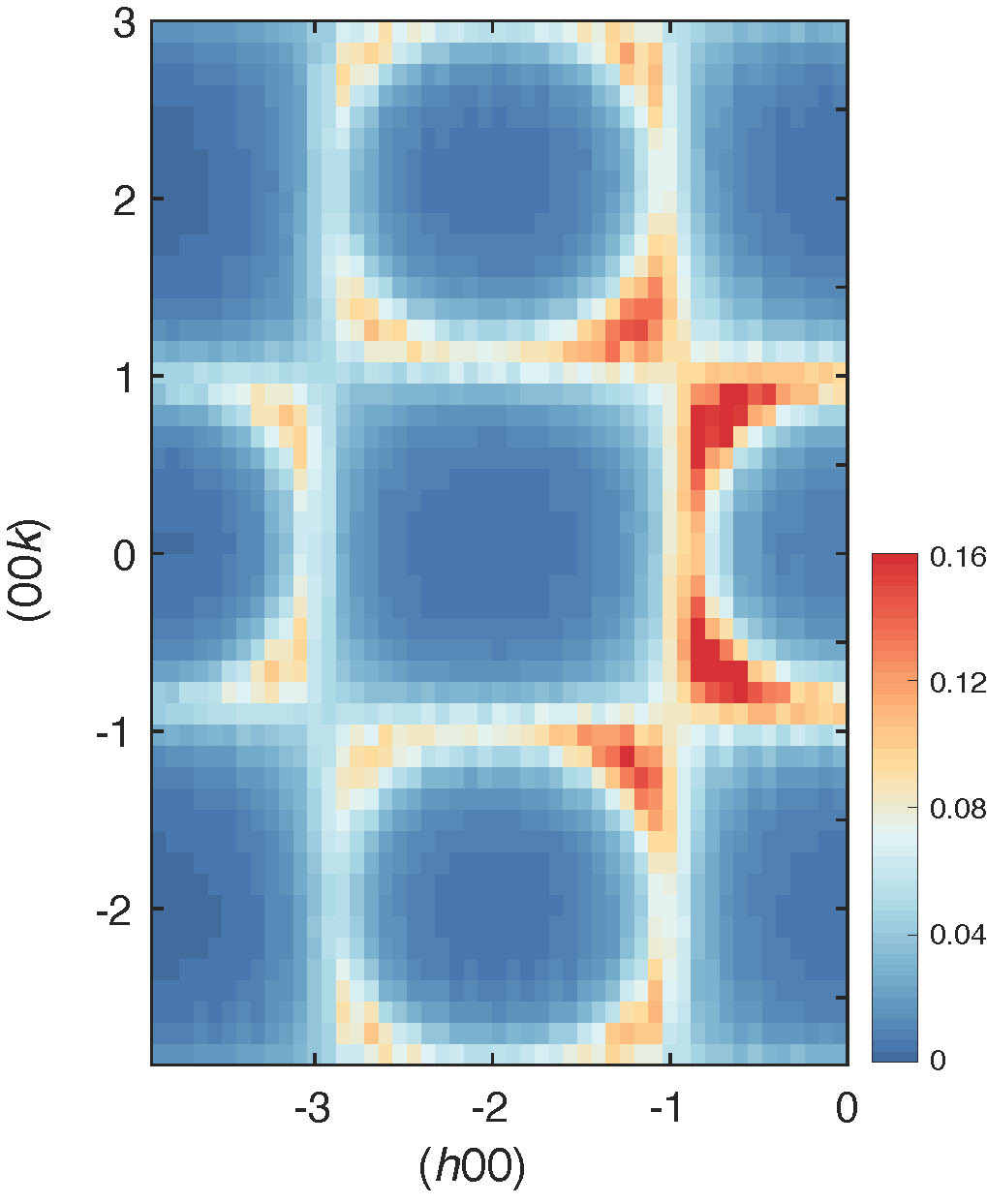
Using linear spin wave theory, we compared different spin models against the INS spectra collected on a powder sample of MnSc2S4. Fig. S1a and b reproduce the experimental data and the spin wave calculation results for the -- model with K, K, and K as presented in the main text, respectively. For the - model with , if the spectra at Å was fitted to the experimental data, the calculated INS intensity will reach meV at Å as shown in Fig. S1c, which is higher than the experimental bandwidth of meV. Therefore, the third-neighbour coupling is necessary to achieve a good fit for the INS spectra. The ratio is now increased to as compared to 0.85 from neutron diffuse scattering 1, indicating that the lattice is even more frustrated than anticipated before. As shown in Fig. S2, at temperatures above , the -- model leads to stronger intensities at around 0.75 0.75 0), which reproduces the intensity contrast within the spiral surface that was observed in our previous experiment 1.
Recent density functional theory (DFT) calculations 2 suggest a different -- model with K, K, and K. From the calculated INS spectra shown in Fig. S1d, we see that this DFT model produces a magnon bandwidth that is higher than the experimental observation. Compared to the coupling strengths fitted from the spin wave dispersions, the DFT model overestimates the coupling strength for and .
Theoretical phase diagram from the Monte Carlo simulations
Fig. S3 plots the calculated phase diagram obtained from Monte Carlo simulations using the perturbed spin Hamiltonian (Eq. 1 in the main text). The , , and couplings are fixed to the spin wave fits of the INS spectra, while the anisotropy terms are determined to be K and K after exploring the stability of the triple- phase as discussed below. The color scale denotes the absolute value of the total scalar spin chirality with , where indexes the elementary triangles of sites , , and in the (111) layers.
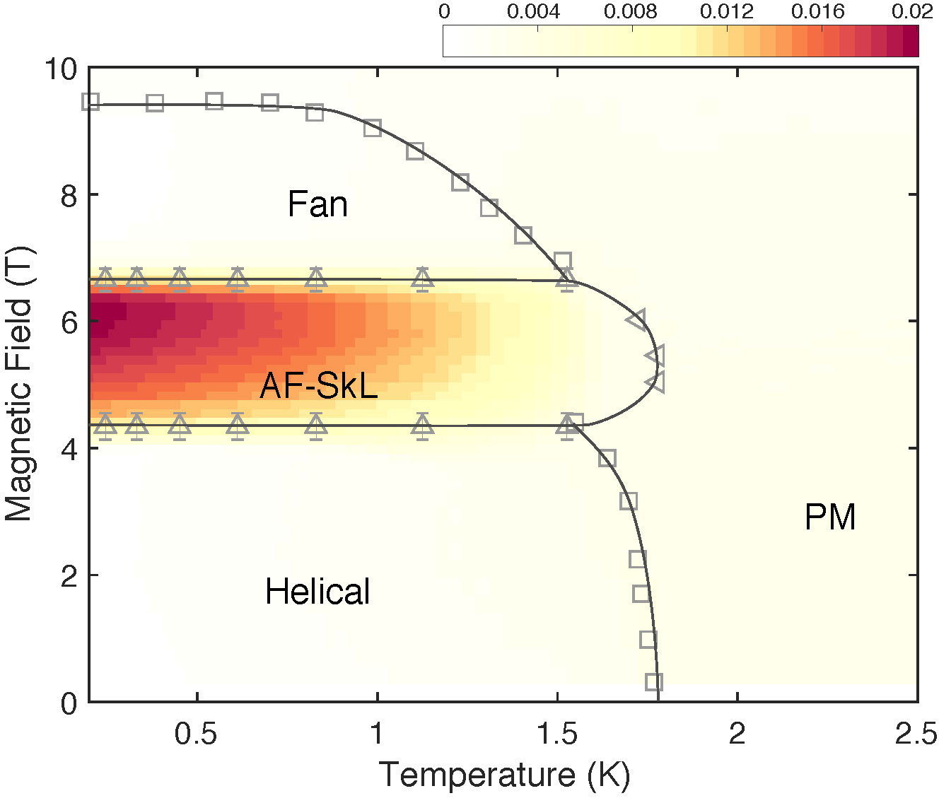
In zero magnetic field the single- helical state is identified by . The transient collinear and incommensurate phases found experimentally in the vicinity of (Ref. 1) are not reproduced in our simulations possibly due to thermal fluctuations and finite size effects, and a detailed exploration in the transitional regime is deferred for future analysis. In applied magnetic fields the triple- phase is identified by sharp increase of the total scalar spin chirality, which evidences a magnetic structure that is topologically different from the single- helical phase. Contrary to the skyrmion lattice that are stabilized by the antysimmetric Dzyaloshinskii-Moriya interactions 3, here the winding direction can be either clockwise or anti-clockwise since the model preserves the inversion symmetry in the (111) plane 4. This implies a spontaneous symmetry breaking in the AF-SkL phase.
Two complementary methods have been employed to clarify the AF-SkL state in the Monte Carlo simulations. One is to directly check the magnetic textures in real space as exemplified in Fig. 4 of the main text, another is to calculate the magnetic structure factors in reciprocal space that can be directly compared to the neutron diffraction results. In the latter method, the skyrmion phase can be identified by the six Bragg spots located in the plane perpendicular to the magnetic field. Figure S4 shows the calculated magnetic structure factors in and planes at K and T using a super-lattice over 500 averaged copies.
In order to illustrate the stability of the triple- phase and explain how did we determine the strength of the perturbation terms, we compare the phase diagrams calculated with different strength of in Fig. S5. When the strength of is reduced from K to K, the stability region of the triple- phase will also become reduced and thus deviates from our experimental observation. On the other hand, when the strength of is increased to K, although the stability region of the triple- phase remains almost the same, a new chiral phase emerges at lower magnetic fields, which is possibly a multiple- state that is different from the skyrmion, fractional skyrmion, or meron lattices. Finally, when the sign of become positive with K, the triple- phase will disappear completely. Therefore, the perturbation term can be determined to be K.
Analytical expression for the AF-Sk lattice
As confirmed in many different types of skymion lattices, the magnetic structure of each -component of the triple- structure is often related to the single- structure observed in zero field. A well-known example is the Bloch-type skyrmion lattice in MnSi (Ref. 3), where the helical components are derived from the zero-field helical phase. Similar arguments hold for the cycloidal components of the Néel-type skyrmion lattice observed in GaV4S8 (Ref. 5). Therefore, considering the helical and collinear structures that are observed in MnSc2S4 at zero field, we can express its field-induced triple- structure through the ansatz:
| (1) |
where is the normalization factor that fixes the spin magnitude to , () is the amplitude for spin modulation perpendicular (parallel) to the [111] direction with phase factor (), are the three propagation vectors (0.75 0), (0.75 0 ), and (0 0.75 ), are the unitary vectors that form cartesian coordinate systems with the corresponding and , and is an homogeneous contribution to the magnetization along .
Assuming equal magnitude for and , and without loss of generality, the case of and corresponds to helical and collinear components, respectively (see Fig. S6a). Note that for the zero-field collinear structure, the spin directions are canted out of the (111) plane by according to our previous refinement 1, and such a canting has been taken into account in our expression. Therefore, by varying , we can construct different triple- structures with -components covering the observed collinear structure, helical structure, and most importantly, a general distorted structure that lies in-between the collinear and helical phases.
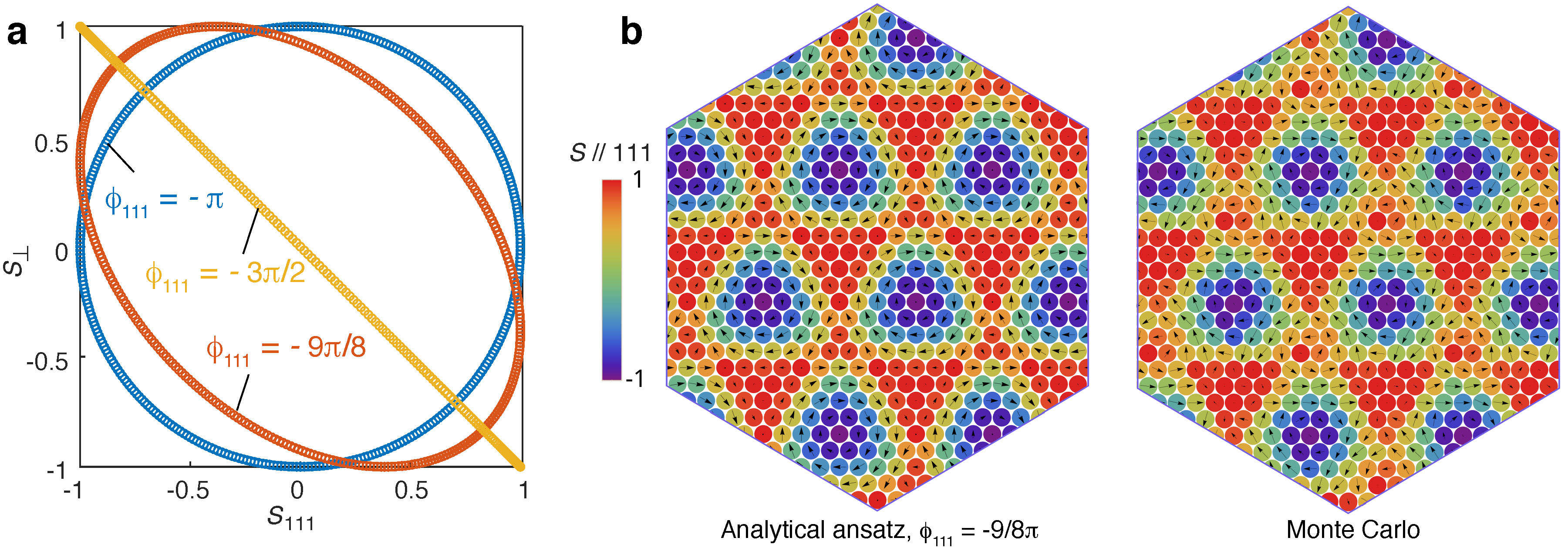
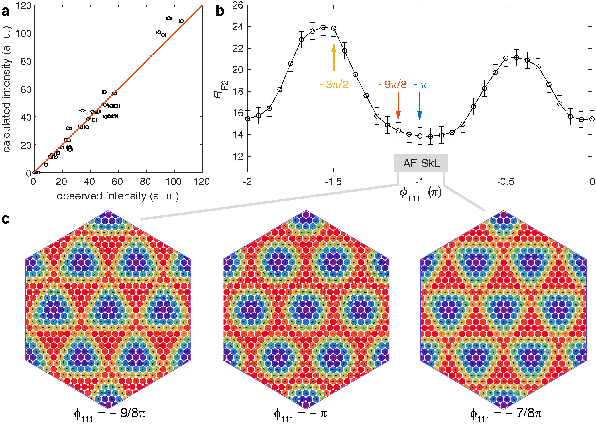
Figure S6b shows the representative magnetic structure of the proposed ansatz for one sublattice in the (111) plane together with that obtained from the Monte Carlo simulations. Assuming , the parameter set of , , and , the proposed ansatz well reproduces the magnetic structure obtained in the Monte Carlo simulations. Two very important details can be observed from this result. First, unlike what happens in the typical skyrmion lattice, the internal phase for the spin configuration is different for the perpendicaular and parallel component of the spin . Secondly, the condition is not satisfied as usual in triple- phases 4.
Refinement of the neutron diffraction dataset in the triple- phase
With the ansatz presented in the previous section, we can directly verify the antiferro-magnetic skyrmion lattice by comparing its magnetic structure factors with the neutron diffraction intensities of magnetic Bragg peaks. Details for the neutron diffraction experiment can be found in the Methods section. As shown in Fig. S7a, the fractional antiferromagnetic skyrmion lattice obtained in the Monte Carlo simulation fits the neutron diffraction dataset very well, with -factors and .
By varying the phase factors, we compared the refinement results from different triple- structures that are composed of general distorted helical components. Fig. S7b summarizes the dependence of the factor on . The best refinement was achieved in the region of with comparable -factors, justifying the value of obtained from the Monte Carlo simulations. More importantly, as shown in Fig. S7c, in the whole regime of , the triple- structure can always be described as a fractional AF-SkL, that is, each (111) plane exhibit a three-sublattice antiferromagnetic alignment, and a fractional skyrmion lattice emerges in each sublattice. The only difference in these structures is a slight variation in the fractionalization. Therefore, our neutron diffraction results strongly support the emergence of a fractional three-sublattice AF-SkL in MnSc2S4.
References
- Gao et al. 2017 S. Gao, O. Zaharko, V. Tsurkan, Y. Su, J. S. White, G. S. Tucker, B. Roessli, F. Bourdarot, R. Sibille, D. Chernyshov, T. Fennell, A. Loidl, and C. Rüegg, Spiral spin-liquid and the emergence of a vortex-like state in MnSc2S4, Nat. Phys. 13, 157 (2017).
- Iqbal et al. 2018 Y. Iqbal, T. Müller, H. O. Jeschke, R. Thomale, and J. Reuther, Stability of the spiral spin liquid in MnSc2S4, Phys. Rev. B 98, 064427 (2018).
- Mühlbauer et al. 2009 S. Mühlbauer, B. Binz, F. Jonietz, C. Pfleiderer, A. Rosch, A. Neubauer, R. Georgii, and P. Böni, Skyrmion lattice in a chiral magnet, Science 323, 915 (2009).
- Okubo et al. 2012 T. Okubo, S. Chung, and H. Kawamura, Multiple- states and the skyrmion lattice of the triangular-lattice Heisenberg antiferromagnet under magnetic fields, Phys. Rev. Lett. 108, 017206 (2012).
- Kézsmárki et al. 2015 I. Kézsmárki, S. Bordacs, P. Milde, E. Neuber, L. M. Eng, J. S. White, H. M. Rønnow, C. D. Dewhurst, M. Mochizuki, K. Yanai, H. Nakamura, D. Ehlers, V. Tsurkan, and A. Loidl, Néel-type skyrmion lattice with confined orientation in the polar magnetic semiconductor GaV4S8, Nat. Mater. 14, 1116 (2015).